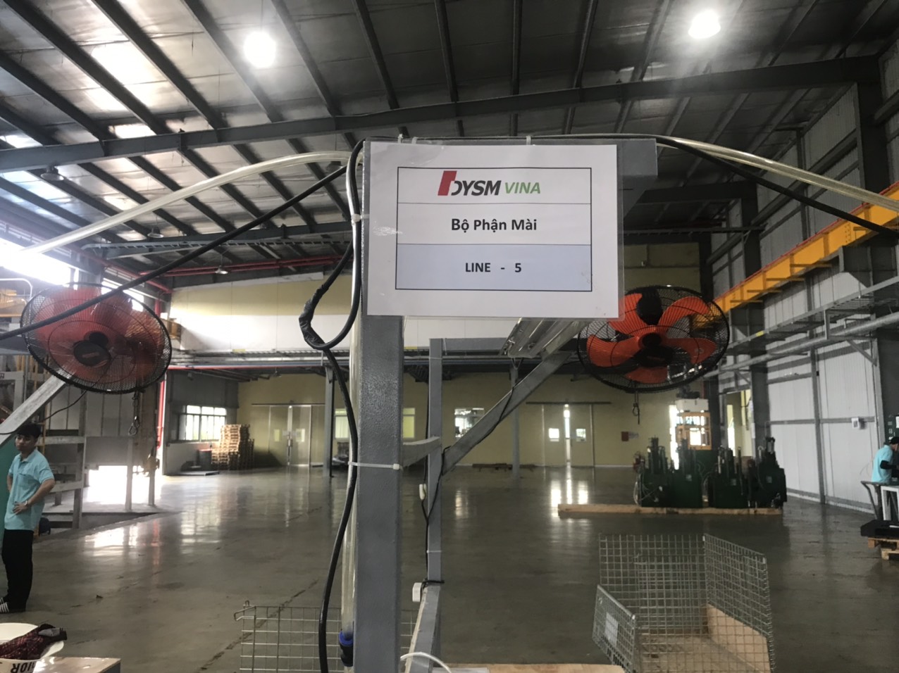

[Adjusting clearance between stamping parts and mating parts](https://dewintech.com/blog/how-clearance-between-stamped-parts-mating-adjusted-should/) is where most fit-up failures start. I learned this the hard way on a bracket order our team managed out of Vietnam.
To adjust clearance between stamping parts and mating parts, set punch-to-die clearance at 5%–15% of material thickness per side based on material hardness, verify fit with gauges or CMM on trial parts, then fine-tune tooling with shims, grinding, or insert changes before mass production.
That short answer covers the basics. But real projects are messier. Below, I break down how to get the clearance right, how to check it, and how to fix it with your supplier.
How do I determine the right clearance tolerance for stamped parts and their mating components?
A few years back, our engineers reviewed a client drawing for a Z-fold mounting clip. The screw hole tolerance was fine, but nobody had defined the punch-die clearance. That gap caused burrs that blocked assembly.
Determine clearance by starting at 5%–15% of material thickness per side. Use smaller values (4%–6%) for soft aluminum, larger values (8%–12%) for stainless or hardened steel. Then tighten the range further for precision holes, mating slots, or features that must align during assembly.
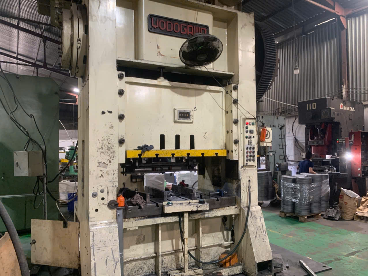
There are actually two different clearances at play, and buyers often confuse them. The first is the punch-to-die gap inside the stamping tool. The second is the assembly fit gap between the stamped part and its mating component. Both matter. If the tooling clearance is wrong, the edges and hole sizes drift. Then the assembly gap you designed in CAD no longer works in real life.
Start with material type and thickness
Material is the biggest driver. Thicker and harder stock needs more clearance. Softer and thinner stock needs less. Here are the starting ranges we use when quoting custom stamped parts for U.S. clients:
| Material | Typical Clearance (per side) | Notes |
|---|---|---|
| Soft aluminum | 4%–6% of thickness | Clean edge, low burr risk |
| Mild steel | 6%–10% of thickness | Good balance of edge quality and tool life |
| Stainless steel | 8%–12% of thickness | Harder material needs more room |
| Spring steel / hardened | 10%–13% of thickness | Tight clearance chips the punch |
| Shaving operations | 1%–1.5% of thickness | Special case for precision edges |
Then adjust for the feature, not just the part
One value never fits the whole die. We ask our tooling partners to calculate clearance station by station. A small piercing punch under 3 mm should sit at the low end of the range. A large blanking contour over 50 mm can run at the high end. For irregular shapes, use the smallest corner radius to set the clearance, because tight corners crack first.
Finally, think about the mating side. If the stamped hole receives a screw or a tab, a burr on the wrong face can raise the part off its seat. In our experience, defining burr direction 1 on the drawing prevents most of these surprises.
What tools or methods can I use to measure and verify clearance before mass production?
The trade-off we weigh on every new tool is speed versus certainty. A feeler gauge check takes minutes. A full CMM study 2 takes days. Choosing the right method depends on how critical the mating fit is.
Verify clearance using feeler gauges for accessible die stations, burr-height and shear-zone inspection on trial parts, go/no-go gauges for mating holes, optical comparators for edge profiles, and CMM measurement of punch and die geometry for critical or high-precision tooling.

Measurement is where theory meets the shop floor. On paper, the die might show 8% clearance per side. In practice, grinding tolerances, assembly errors, and wear can shift the effective gap. So we never trust the drawing alone. We verify.
Match the method to the risk level
| Method | Best For | Accuracy | Cost/Time |
|---|---|---|---|
| Feeler/shim gauge | Accessible die stations | Moderate | Very low |
| Light-band check | Quick visual gap assessment | Low | Very low |
| Burr height + shear-zone inspection | Trial parts, indirect clearance check | Good | Low |
| Go/no-go gauges | Mating holes and slots | Good | Low |
| Optical comparator | Edge profiles, small features | High | Moderate |
| CMM | Critical tooling, PPAP dimensional reports | Highest | High |
Read the part, not just the tool
The cut edge tells a story. A healthy sheared edge shows a rollover zone, a shiny burnish band 3, a fracture zone, and a small burr. If the burnish band is too wide or the edge shows double burnishing, the clearance is too tight. If the burr is tall and the edge is rough, the clearance is too loose. We train our inspectors in Vietnam and China to read these signals during first-off checks.
Prove the mating fit, not just the dimensions
Here is a step we insist on before any tool release. Take trial stamped parts 4 and physically assemble them with the actual mating component or a master gauge. Numbers on a report can all pass while the assembly still binds, usually because of burr direction or springback. A five-minute fit trial catches what a dimension table misses. For repeat programs, we build simple assembly fixtures so this check happens on every production lot, not just the first one.
How can I work with my supplier to correct clearance issues found during PPAP or first article inspection?
A U.S. purchasing manager once sent us photos of clips that would not seat flush on their panel. The PPAP report 5 looked clean. The problem turned out to be burr direction, and it took one structured call to solve it.
Correct clearance issues by sharing measured data and photos with the supplier, agreeing on root cause (tooling gap, wear, or springback), then approving a specific fix such as shimming, regrinding, insert replacement, or die adjustment, followed by a re-run and updated first article submission.

Fixing clearance problems is a joint project, not a blame game. In our role coordinating between U.S. buyers and Asian factories, we have found that the speed of resolution depends on how clearly the problem is defined. Vague complaints like "the parts do not fit" lead to weeks of back-and-forth. Data leads to answers.
Follow a structured correction process
- Document the failure. Send measurements, burr photos, and assembly photos. Mark which feature fails and on which face.
- Confirm the measurement method. Make sure both sides measure the same feature the same way. Clarify whether clearance is quoted per side or total. This single confusion causes many false disputes.
- Agree on root cause. Is the clearance wrong by design? Is the tool worn? Or is springback moving the feature after cutting? Each cause has a different fix.
- Approve the specific corrective action. Common tooling fixes include adding or removing shims, precision grinding the punch or die, replacing worn inserts, or adjusting the die set alignment.
- Re-run and re-submit. Require a new first article from the corrected tool, plus a physical fit check with the mating part.
- Update the control plan. Add the failed feature to the ongoing inspection checklist so it stays monitored.
Set expectations on timing and cost upfront
Tooling corrections take time. A shim adjustment might take a day. A new insert can take one to two weeks. When we manage these corrections for clients, we lock the timeline in writing and hold a follow-up review before the re-run ships. That discipline is what turns a PPAP failure into a one-time event instead of a recurring headache.
What design or process adjustments help prevent recurring clearance problems in future production runs?
The most valuable lesson from years of custom-parts sourcing is simple: clearance problems that keep coming back are almost never random. They are baked into the design or the process controls.
Prevent recurring clearance problems by designing holes at least 1.5× thickness apart and 2× thickness from bends, specifying burr direction on drawings, using simulation before tooling, scheduling regular punch regrinding, and applying SPC to track edge quality and tool wear trends.

Prevention splits into two halves: better design and better process control. Both are cheaper than firefighting.
Design rules that make clearance predictable
Features placed too close to bends or to each other distort during forming. Once a hole distorts, no amount of tooling adjustment restores the mating fit. These spacing rules solve most of it before the die is ever cut:
| Design Rule | Recommended Minimum | Why It Matters |
|---|---|---|
| Hole-to-hole spacing | 1.5× material thickness | Prevents tearing and distortion between holes |
| Hole-to-bend distance | 2× material thickness | Stops holes from stretching into ovals during forming |
| Corner radius on contours | Avoid sharp internal corners | Tight radii crack and force clearance compromises |
| Burr direction callout | Specified on drawing | Keeps burrs away from mating surfaces |
| Slot width for mating tabs | Tab thickness + fit allowance | Separates assembly fit from tooling tolerance |
Process controls that catch drift early
Tools wear. Material lots vary. The effective clearance on day one is not the clearance after 200,000 hits. So we build three habits into production for repeat programs. First, schedule punch and die regrinding 6 based on hit count, not on failure. Second, track burr height with SPC across batches, because a rising trend flags wear before parts go out of tolerance. Third, freeze the material spec with the supplier, since a switch to a harder lot can wreck a clearance that worked fine before.
For new tools, simulation helps too. CAE and FEA software 7 can predict springback and optimal clearance before steel is cut. On progressive dies, this matters even more, because springback accumulates across stations and each one needs its own calibration.
Conclusion
Bad clearance quietly ruins fit, schedules, and budgets. Set it by material and feature, verify it with real measurements and fit trials, correct it with structured supplier communication, and prevent it through design rules and process control. Get those four steps right, and your stamped parts will mate correctly from the first run to the last.
Frequently Asked Questions
How do I determine the right clearance tolerance for stamped parts and their mating components?
A few years back, our engineers reviewed a client drawing for a Z-fold mounting clip. The screw hole tolerance was fine, but nobody had defined the punch-die clearance. That gap caused burrs that blocked assembly.
What tools or methods can I use to measure and verify clearance before mass production?
The trade-off we weigh on every new tool is speed versus certainty. A feeler gauge check takes minutes. A full CMM study 2 takes days. Choosing the right method depends on how critical the mating fit is.
How can I work with my supplier to correct clearance issues found during PPAP or first article inspection?
A U.S. purchasing manager once sent us photos of clips that would not seat flush on their panel. The PPAP report 5 looked clean. The problem turned out to be burr direction, and it took one structured call to solve it.
Footnotes
1. Background on manufacturing burrs directly relevant to clearance and assembly fit issues. ↩︎
2. NIST sets metrology standards underlying coordinate measuring machine verification methods. ↩︎
3. Explains the shearing edge zones like burnish and fracture referenced in clearance inspection. ↩︎
4. Alibaba is a major sourcing platform for custom stamped parts and mating components. ↩︎
5. PPAP documentation aligns with ISO-based quality management and part approval frameworks. ↩︎
6. Tooling maintenance schedules support standardized quality practices under ISO 9001 guidance. ↩︎
7. Explains the simulation method used to predict springback and optimal clearance. ↩︎