Every week, our quality team in Vietnam and China processes incoming sheet metal shipments for U.S. buyers who cannot afford a single non-conforming part reaching their assembly line. The problem is real: a missed burr, an out-of-tolerance bend, or a wrong alloy can halt production and cost thousands. Without a structured incoming inspection process 1, these defects slip through — and the buyer pays the price. That is exactly why we built a rigorous, step-by-step inspection workflow that catches issues before they become costly failures.
Buyers conduct incoming inspection for sheet metal fabrication by verifying documentation and material certifications, performing visual and dimensional inspection with calibrated tools like calipers, micrometers, and CMMs, applying sampling plans such as AQL, and documenting all findings to accept, reject, or quarantine each shipment.
This guide walks you through each stage of the process. We will cover how to build a reliable checklist, which measurement tools to use, how to validate material certifications and surface finishes, and what to do when parts fail to meet your drawing requirements. Let us get into it.
How can I develop a reliable incoming inspection checklist for my custom sheet metal parts?
A lesson we learned early in our supply chain management 2 work: the checklist is not just a form — it is the backbone of your entire quality control plan 3. Without one, inspectors make subjective calls. With one, every shipment gets the same fair, thorough evaluation.
To develop a reliable incoming inspection checklist, start with your engineering drawing, list every critical dimension and tolerance, define visual acceptance criteria, specify material verification requirements including mill test reports, and assign a clear accept/reject/quarantine disposition for every check item.

Start with Your Drawing and Specifications
Your checklist must mirror your engineering drawing 4. Every critical feature on the drawing needs a corresponding line item on the checklist. This includes overall dimensions, hole locations, bend angles, material type, thickness, surface finish, and any geometric dimensioning and tolerancing 5 (GD&T) callouts.
I recommend grouping your checklist into logical sections. Here is a structure that works well for most custom sheet metal parts:
| Checklist Section | What to Include | Priority |
|---|---|---|
| Documentation Review | PO number, packing list, material certifications, revision level | High |
| Packaging Integrity | Damage, moisture, contamination, proper separation of parts | Medium |
| Visual Inspection | Scratches, dents, burrs, weld quality, surface finish, color consistency | High |
| Dimensional Inspection | Critical dimensions, hole diameters, bend angles, overall length/width | High |
| Material Verification | Thickness gauge check, alloy confirmation via mill test report 6s (MTRs) | High |
| Functional Check | Fit with mating parts, assembly trial (if applicable) | Medium–High |
| Disposition | Accept, reject, or quarantine decision with inspector signature and date | High |
Define Your Acceptance Criteria Clearly
Vague criteria lead to arguments. Instead of writing "surface must be clean," write "no scratches deeper than 0.05 mm or longer than 10 mm on visible surfaces." Instead of "dimensions per drawing," specify which dimensions are critical and what the acceptable tolerance band is.
For every line item, your checklist should have three columns: the specification, the actual measured value, and the pass/fail result. This keeps inspection documentation clean and traceable.
Tailor the Checklist to Your Part Complexity
A simple flat bracket does not need the same checklist as a complex multi-bend enclosure with welded inserts. We often create tiered checklists — a basic version for simple parts, and an extended version for parts with welds, tight tolerances, or critical surface requirements. This avoids wasting time on low-risk features while ensuring high-risk features get proper attention.
Include a First Article Inspection (FAI) Section
For new parts or new suppliers, your checklist should include a dedicated First Article Inspection 7 section. The FAI is a comprehensive, 100% dimensional check of the first production sample. It verifies that the supplier's process can produce parts within spec before full production begins. Once the FAI is approved, subsequent shipments can use sampling-based inspection.
What measurement tools and sampling standards should I use to verify my part dimensions?
When one of our U.S. clients asked why a batch of brackets did not fit into their assembly, we traced the issue back to a 0.3 mm deviation in a bend location — something a visual check would never catch. The right measurement tool would have flagged it immediately. Tool selection is not an afterthought. It drives your inspection accuracy.
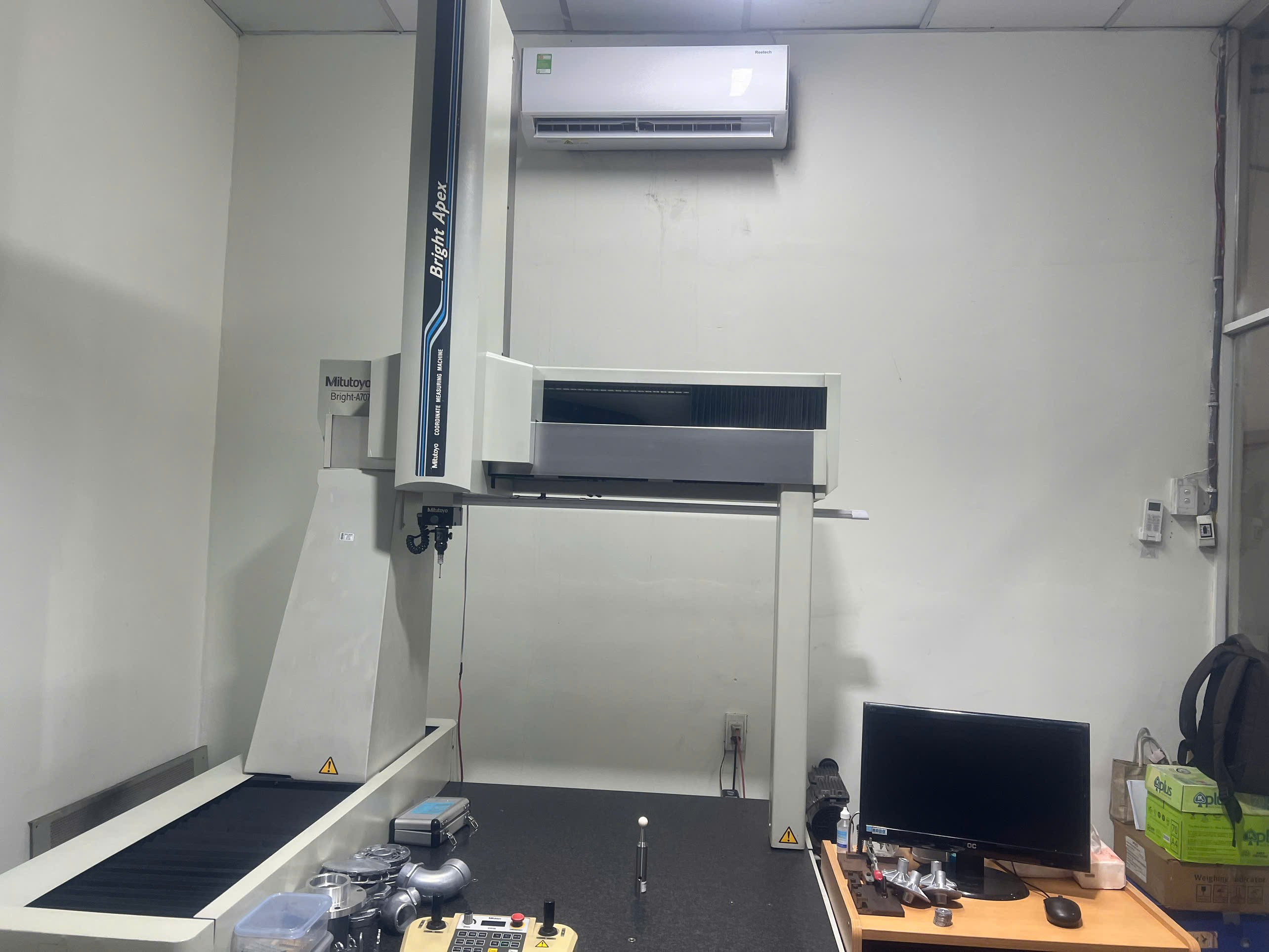
Use calipers for general dimensions, micrometers for thickness verification, height and depth gauges for stepped features, angle gauges for bends, and a Coordinate Measuring Machine (CMM) for complex geometries. Apply AQL-based sampling plans to balance inspection effort with quality risk across your shipment.
Choosing the Right Tool for the Right Measurement
Not every dimension needs a CMM. And not every check can be done with a tape measure. Here is a practical guide to matching tools with measurement types:
| Measurement Type | Recommended Tool | Typical Accuracy | When to Use |
|---|---|---|---|
| Overall length, width | Digital caliper | ±0.02 mm | General dimensional inspection |
| Sheet metal thickness | Outside micrometer | ±0.001 mm | Every shipment — critical for fit and strength |
| Hole diameter | Pin gauges or caliper | ±0.01 mm | Fastener holes, alignment features |
| Bend angle | Digital angle gauge or protractor | ±0.5° | All formed parts |
| Step height / depth | Height gauge / depth gauge | ±0.01 mm | Features relative to a datum surface |
| Complex 3D profiles | Coordinate Measuring Machine (CMM) | ±0.003 mm | Multi-feature parts, GD&T verification |
| Surface roughness | Profilometer | Ra 0.1 µm | Sealing surfaces, aesthetic requirements |
Why Micrometers Matter More Than Calipers for Thickness
A digital caliper can measure thickness, but a micrometer is the better choice. It applies consistent measuring pressure and reads to a finer resolution. Rolling mills sometimes produce sheets that are thicker at the center than at the edges. We always measure thickness at multiple points — near each edge and at the center — to catch this variation. If you rely on a single-point caliper check, you might miss an out-of-spec condition.
When to Use a CMM
A Coordinate Measuring Machine provides automated, high-precision 3D measurements. It is ideal for parts with many features, tight tolerances, or GD&T requirements like true position, flatness, or profile. However, CMMs are not infallible. If a CMM flags a feature as out of tolerance, best practice is to verify that feature with standard inspection methods like calipers or micrometers. Manual tools remain the "gold standard" for final acceptance decisions when discrepancies arise.
Sampling Plans: AQL and Risk-Based Approaches
You cannot inspect every part in a shipment of 5,000 brackets. That is where sampling plans come in. The most common standard is the Acceptance Quality Limit 8 (AQL) system. It tells you how many parts to inspect based on your lot size and acceptable risk level.
| Lot Size | General Inspection Level II — Sample Size | AQL 1.0 (Accept/Reject) | AQL 2.5 (Accept/Reject) |
|---|---|---|---|
| 51–90 | 13 | 0/1 | 1/2 |
| 151–280 | 32 | 1/2 | 2/3 |
| 501–1,200 | 80 | 2/3 | 5/6 |
| 1,201–3,200 | 125 | 3/4 | 7/8 |
| 3,201–10,000 | 200 | 5/6 | 10/11 |
AQL 1.0 is common for critical dimensions. AQL 2.5 might apply to cosmetic checks. For a new supplier or a first production run, many buyers tighten inspection to Level III or even 100% inspection for critical features. As the supplier builds a track record through consistent supplier quality assurance, you can reduce the inspection level to save time and cost.
How do I validate that my supplier's material certifications and surface finishes meet my specs?
One trade-off we weigh on nearly every project is how much to trust the paperwork versus how much to verify in the lab. A material certificate says the sheet is 304 stainless steel. But is it? We have seen cases where the cert was correct but the coil delivered was not the coil the cert was written for. Trust, but verify — that is the rule.
Validate material certifications by cross-checking mill test reports (MTRs) against your spec for alloy, temper, and mechanical properties, then confirm on-site with thickness measurements and visual surface checks. For critical applications, send samples for independent lab testing of chemical composition and hardness.

Understanding Material Certifications
A mill test report, also called a Certificate of Material or Certificate of Conformance, documents the chemical composition, mechanical properties (tensile strength, yield strength, elongation), and heat/lot number of the raw material. Your job is to verify that the values on the report fall within the ranges specified by the relevant material standard — for example, ASTM A240 for stainless steel sheet.
Check these items on every MTR:
- Alloy grade matches your drawing callout (e.g., SS304, AL6061-T6, SPCC).
- Chemical composition values are within the standard's allowable range.
- Mechanical properties meet minimum requirements.
- Heat number or lot number matches the marking on the physical material.
- Mill name and date are present and plausible.
Raw Material Inspection at Your Facility
If you receive raw coils or sheets before fabrication, raw material inspection is your first line of defense. Use a micrometer to verify thickness. Inspect surfaces for rust, oil stains, scratches, or lamination defects. Check that the material is properly labeled and segregated. Our team in Vietnam performs these checks on every coil before releasing material to the production floor, because catching a wrong alloy after cutting and bending means scrapping the entire batch.
Verifying Surface Finishes
Surface finish specs might call for a brushed finish, a specific roughness value (e.g., Ra 1.6 µm), powder coating to a certain thickness, or anodizing to a color standard. Here is how to verify each:
- Surface roughness: Use a profilometer to take readings at multiple points. Compare against the Ra or Rz value on your drawing.
- Coating thickness: Use a coating thickness gauge (magnetic or eddy current type depending on substrate). Check at flat areas and near edges where coating tends to be thinner.
- Visual finish: Compare against an approved reference sample or color chip under standardized lighting. This is especially important for painted or anodized parts where color consistency matters.
- Plating and conversion coatings: Verify with salt spray test reports or adhesion test results provided by the supplier.
When to Send Samples for Lab Testing
For safety-critical parts, aerospace applications, or when you are onboarding a new supplier, do not rely solely on the supplier's paperwork. Send material samples to an independent lab for chemical composition analysis (using optical emission spectrometry) and hardness testing (Rockwell or Vickers). This is a form of non-destructive testing that gives you direct evidence of material properties. It costs relatively little compared to the risk of a field failure.
What steps should I take if my incoming sheet metal shipment fails to match my drawing requirements?
A buyer interaction that shaped our entire non-conformance process happened three years ago. A shipment of 800 custom enclosures arrived at our client's warehouse in Texas with bend angles consistently 2° off spec. The client had no documented process for handling the rejection, so the parts sat in limbo for weeks — blocking their production schedule and creating friction with the supplier. That experience taught us that having a clear rejection workflow is just as important as having a good inspection process.
When a shipment fails your drawing requirements, immediately segregate the non-conforming parts, document the defects with photos and measurements, issue a formal non-conformance report to the supplier, and convene your Material Review Board to decide whether to accept with deviation, rework, return, or scrap the parts.
Step 1: Stop and Segregate
The first action is physical. Move the non-conforming parts away from your accepted inventory. Label them clearly with a rejected tag — red labels or "HOLD" stickers work well. This prevents anyone from accidentally using defective parts in production. In our facilities, we use a dedicated quarantine area with locked shelving for disputed shipments.
Step 2: Document Everything
Take photos of every defect. Record the exact measurements that are out of tolerance, noting which drawing dimension each one references. Your inspection documentation should include the part number, revision, PO number, lot or batch number, the quantity inspected, the quantity rejected, and a clear description of each defect type.
Common sheet metal defects that trigger rejections include:
- Dimensions out of tolerance (length, width, hole position)
- Bend angles outside the specified range
- Burrs exceeding the allowable limit
- Scratches or dents on cosmetic surfaces
- Wrong material or wrong thickness
- Weld defects (porosity, incomplete fusion, spatter)
- Surface finish not matching the spec or reference sample
Step 3: Issue a Non-Conformance Report (NCR)
A formal NCR puts the supplier on notice. non-conformance report 9 It should reference the specific drawing requirements that were violated, include your measurement data and photos, and request a root cause analysis and corrective action from the supplier. This is a key part of supplier quality assurance — it creates a paper trail and drives accountability.
Step 4: Convene the Material Review Board (MRB)
Your MRB — which might be you, your engineer, and your quality manager — reviews the NCR and decides on a disposition:
- Accept as-is: The deviation does not affect fit, form, or function. Document the concession.
- Rework: The supplier or your team can fix the defect (e.g., deburring, re-bending).
- Return to supplier: The parts go back for replacement at the supplier's cost.
- Scrap: The parts are unusable and must be discarded.
Step 5: Communicate and Follow Up
Notify the supplier immediately. Share the NCR, photos, and your disposition decision. Request a corrective action plan with a timeline. Track the corrective action to closure. If the same defect recurs, escalate — tighten your incoming inspection level, request the supplier's outgoing inspection data, or consider qualifying a backup supplier.
Step 6: Update Your Quality Records
Log the non-conformance in your supplier performance tracking system. Over time, this data reveals patterns. Maybe a specific supplier consistently struggles with bend tolerances. Maybe surface finish defects spike during humid months. This data lets you shift to a risk-based inspection strategy — inspecting more rigorously from problematic suppliers and less from proven ones.
Conclusion
A structured incoming inspection for sheet metal fabrication 10 protects your production line, your reputation, and your bottom line. Build your checklist from your drawings, use the right tools, verify every certification, and have a clear process for handling failures. Consistent inspection turns supplier quality from a gamble into a managed outcome. For a deeper dive into the full range of checks you should perform, see our guide on key quality inspection steps for finished sheet metal products.
Frequently Asked Questions
How can I develop a reliable incoming inspection checklist for my custom sheet metal parts?
A lesson we learned early in our supply chain management 2 work: the checklist is not just a form — it is the backbone of your entire quality control plan 3 . Without one, inspectors make subjective calls. With one, every shipment gets the same fair, thorough evaluation.
What measurement tools and sampling standards should I use to verify my part dimensions?
When one of our U.S. clients asked why a batch of brackets did not fit into their assembly, we traced the issue back to a 0.3 mm deviation in a bend location — something a visual check would never catch. The right measurement tool would have flagged it immediately. Tool selection is not an afterthought. It drives your inspection accuracy.
How do I validate that my supplier's material certifications and surface finishes meet my specs?
One trade-off we weigh on nearly every project is how much to trust the paperwork versus how much to verify in the lab. A material certificate says the sheet is 304 stainless steel. But is it? We have seen cases where the cert was correct but the coil delivered was not the coil the cert was written for. Trust, but verify — that is the rule.
Footnotes
1. Defines the steps and importance of incoming quality control. ↩︎
2. Provides a comprehensive definition and overview of SCM. ↩︎
3. Describes the purpose and elements of a quality control plan. ↩︎
4. Replaced HTTP 405 link with a detailed explanation of engineering drawing standards (ASME, ISO, DIN). ↩︎
5. Explains the system for defining and communicating engineering tolerances. ↩︎
6. Defines MTRs and their importance for material verification. ↩︎
7. Replaced HTTP 404 link with a comprehensive guide to First Article Inspection (FAI). ↩︎
8. Explains the AQL sampling method for product inspections. ↩︎
9. Describes the purpose and process of documenting non-conformities. ↩︎
10. Replaced HTTP unknown link with a working, informative page on sheet metal fabrication basics from a manufacturing company. ↩︎