Every week, our team reviews rejected parts from suppliers who misread drawings — and the root cause is almost always a broken handoff between design and production.
CAD/CAM software streamlines sheet metal design to production by integrating 3D parametric modeling with automated CNC programming, enabling accurate flat pattern generation, bend allowance calculations, and material optimization — eliminating translation errors and reducing lead times by up to 30–50%.
The gap between a finished design file and a finished part is where most problems hide 3D parametric modeling 1. In the sections below, I break down exactly how modern CAD/CAM integration closes that gap, prevents rework, cuts costs, and keeps your delivery schedule intact.
How can CAD/CAM software help me eliminate design errors before my sheet metal parts go into production?
A lesson we learned early at DEWIN: catching a tolerance mistake on screen costs minutes, but catching it after cutting costs weeks and thousands of dollars in scrapped material bend allowance calculations 2.
CAD/CAM software eliminates design errors before production by running automated manufacturability checks, simulating bend sequences, and validating flat patterns against real material properties — so issues surface digitally, not on the shop floor, ensuring right-first-time results.
Where Design Errors Actually Come From
Most design errors in sheet metal fabrication do not come from bad engineering PTC Creo 3. They come from bad translation. A designer creates a 3D model. Someone else exports it. A third person imports it into a different program. Each step introduces risk. Dimensions shift. Tolerances get rounded. Bend notes disappear.
In our experience sourcing custom parts from factories across Vietnam and broader Asia, we see this pattern repeat. The designer's intent is correct, but the file that reaches the CNC machine is not. Integrated CAD/CAM software solves this by keeping design and manufacturing data in one environment. There is no export-import chain. The 3D parametric model is the single source of truth.
How Automated Checks Work
Modern CAD/CAM platforms run design for manufacturability checks 4 automatically. Here is what they verify:
| Check Type | What It Catches | Why It Matters |
|---|---|---|
| Bend radius validation | Radii too tight for the selected material | Prevents cracking during forming |
| Minimum flange length | Flanges too short for the press brake tooling | Avoids tooling collisions |
| Hole-to-edge distance | Holes placed too close to a bend line | Stops deformation around holes |
| Flat pattern interference | Overlapping geometry when unfolded | Ensures the part can actually be cut from flat stock |
| Material thickness mismatch | Model thickness vs. specified gauge | Eliminates ordering the wrong raw material |
These checks run in seconds. Without them, the first sign of a problem is a bad part off the machine. With them, the designer fixes the issue before the file ever leaves the screen.
The Role of Simulation in Error Prevention
Simulation goes a step further. Software like Autodesk Fusion 5 or PTC Creo can simulate the entire bending sequence. You see exactly how the sheet folds, where stress concentrates, and whether the part springs back beyond tolerance. This digital prototyping step replaces the old method of trial bending on the shop floor.
When we manage production for U.S. clients, we require our partner factories to run these simulations before first-article production. It is one of the most effective ways to achieve right-first-time quality. The result: fewer rejected parts, less wasted material, and no surprises during final inspection.
Will CAD/CAM integration reduce my lead times and help me get my custom parts delivered on schedule?
One of our U.S. clients once waited an extra three weeks for a batch of mounting brackets because the factory had to manually re-program every toolpath after a design revision — a delay that a unified CAD/CAM system would have prevented entirely.
CAD/CAM integration reduces lead times by automating toolpath generation, nesting, and flat pattern creation directly from the 3D model — cutting programming time by hours and enabling faster iteration cycles so custom parts ship on schedule.
The Traditional Workflow vs. the Integrated Workflow
To understand the time savings, compare the two approaches side by side.
| Step | Traditional (Siloed) Workflow | Integrated CAD/CAM Workflow |
|---|---|---|
| Design | 3D model created in standalone CAD | 3D model created in integrated platform |
| Export | Model exported as STEP, DXF, or IGES | No export needed — model stays in system |
| Import & verify | CAM operator imports file, checks for errors | CAM reads directly from design model |
| Flat pattern | Manually generated or recalculated | Automatically generated with bend allowances |
| Nesting | Separate nesting software required | Built-in nesting optimization |
| CNC programming | Manually written or adjusted G-code | Automated CNC programming 6 from model |
| Design revision | Repeat entire cycle from export step | Model updates propagate instantly |
Each handoff in the siloed workflow adds hours or days. Multiply that by the number of unique parts in a project, and you see why lead times balloon.
Where Time Is Actually Saved
The biggest time savings come from three areas:
1. Automated flat pattern generation. In a traditional setup, a programmer must manually unfold the 3D model and calculate bend allowance for each bend. Integrated software does this instantly. For a part with six bends, this alone can save 30 minutes to an hour per part.
2. Nesting software. Automated nesting arranges parts on a sheet to minimize waste. It also generates the cutting path for the laser or punch press. Without integration, this step requires importing flat patterns into a separate program, adjusting them, and re-exporting.
3. Revision handling. Design changes are inevitable. In an integrated system, a change to the 3D model instantly updates the flat pattern, the nest, and the CNC code. In a siloed system, every downstream file must be manually regenerated.
Real-World Impact on Delivery Schedules
Industry data suggests integrated CAD/CAM can reduce lead times by 30–50%. In our project management experience, the improvement is most dramatic on complex, multi-part assemblies where dozens of unique components must be programmed. Cloud collaboration tools further accelerate this by letting designers, engineers, and fabricators work on the same model simultaneously — no more emailing files back and forth and waiting for responses across time zones.
For purchasing managers who source from Asia, this speed translates directly into schedule reliability. When the factory can turn around CNC programming in hours instead of days, there is more buffer for quality checks and shipping.
How does CAD/CAM technology ensure my supplier follows my exact drawing specifications without constant rework?
During a recent supplier audit in Vietnam, we discovered that an operator had been manually adjusting bend angles by two degrees to compensate for what he believed was springback — but the original CAD file already accounted for it, and his adjustment was creating out-of-spec parts.
CAD/CAM technology ensures suppliers follow exact drawing specifications by embedding tolerances, bend allowances, and material parameters directly into the machine code — removing manual interpretation and ensuring every cut, punch, and bend matches the digital model precisely.
The Interpretation Problem
Here is the core issue. A 2D drawing is a communication tool. It tells the machinist what the part should look like. But it does not tell the machine what to do. Someone must interpret the drawing and translate it into actions. That interpretation step is where specifications get lost.
Common interpretation failures include:
- Misreading geometric dimensioning and tolerancing 7 (GD&T) symbols
- Using a default bend allowance instead of the one specified for the material
- Ignoring notes about surface finish or grain direction
- Applying the wrong deduction factor for a specific tooling setup
When CAD/CAM software generates the machine code directly from the 3D model, these interpretation errors disappear. The software does not guess. It uses the exact material thickness, exact bend radius, and exact K-factor defined in the model.
How Specifications Travel from Design to Machine
Think of integrated CAD/CAM as a pipeline. Each specification flows through without manual re-entry.
| Specification | How CAD Captures It | How CAM Uses It |
|---|---|---|
| Material type & thickness | Defined as a sheet metal parameter in the model | Used to calculate bend deductions and cutting speed |
| Bend radius | Set per bend or globally in the model | Applied directly to press brake programming |
| Hole sizes and positions | Modeled as features with exact coordinates | Converted to punch or laser coordinates |
| Tolerances | Attached to dimensions in the model | Used to set machine offsets and inspection criteria |
| Surface finish | Noted in model metadata | Determines cutting parameters (speed, gas type) |
This pipeline eliminates the "telephone game" that happens when specifications pass through multiple people and multiple file formats.
The Quality Control Advantage
For our clients, many of whom require PPAP-level documentation 8, integrated CAD/CAM provides another benefit: traceability. The machine code can be traced back to a specific revision of the 3D model. If a part fails inspection, we can check whether the issue was in the design, the code generation, or the machine setup. There is no ambiguity.
We also use the flat pattern output from CAD/CAM as the basis for first-article inspection reports. The inspector compares the physical part to the same flat pattern the machine used. This closed loop is what drives right-first-time production and eliminates the cycle of rework that frustrates so many purchasing managers.
Addressing the Legacy Machine Challenge
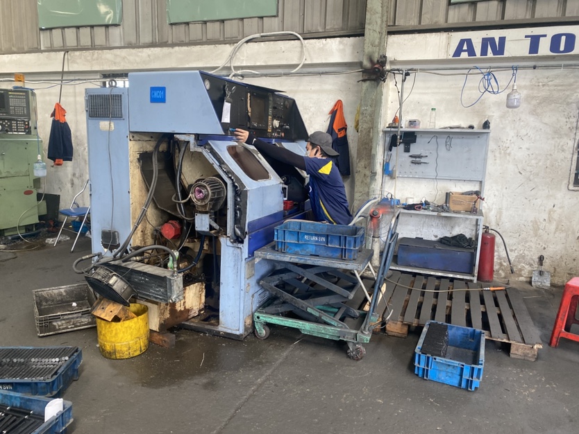
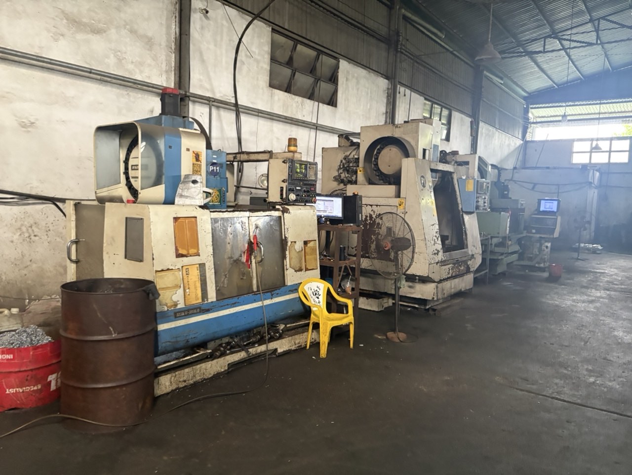
One valid concern is whether modern CAD/CAM software works with older CNC machines. The answer depends on the machine's controller. Most CAM systems can post-process code for a wide range of controllers, including older Fanuc, Siemens, and Mazak models. However, some very old machines lack the digital connectivity to accept files directly and require manual code transfer via USB or even serial port. In those cases, the benefit of automated code generation still applies — only the file transfer method is less convenient.
Can I lower my overall manufacturing costs by using CAD/CAM software to optimize my sheet metal designs?
A trade-off we weigh on every project is whether investing in better upfront engineering saves enough downstream to justify the cost — and with sheet metal, the answer is almost always yes.
CAD/CAM software lowers manufacturing costs by optimizing nesting to reduce material waste by 15–20%, automating CNC programming to cut labor hours, minimizing rework through simulation, and enabling design for manufacturability analysis that simplifies fabrication without compromising function.
Breaking Down the Cost Drivers
To understand where CAD/CAM saves money, you need to understand where money is spent in a typical sheet metal fabrication workflow. The major cost buckets are:
- Raw material — the sheet stock itself
- Machine time — laser cutting, punching, bending
- Programming labor — setting up toolpaths and sequences
- Rework and scrap — parts that fail inspection or cannot be assembled
- Logistics and delays — expedited shipping to recover lost time
CAD/CAM software directly reduces costs in the first four categories. And by preventing delays, it indirectly reduces the fifth.
Material Optimization Through Nesting
Nesting is the process of arranging flat patterns on a sheet to use as much material as possible. Manual nesting by an experienced programmer might achieve 75–80% material utilization. Advanced nesting algorithms 9 in modern CAD/CAM platforms consistently achieve 85–90% or higher.
On a project with 500 sheets of 304 stainless steel, a 10% improvement in utilization can save 50 sheets. At current market prices, that is a significant cost reduction. The software also considers grain direction, sheet edge margins, and cutting kerf width — details that manual nesting often overlooks.
Design for Manufacturability Saves More Than You Think
Production efficiency is not just about the machine. It is about the design itself. CAD/CAM tools with design for manufacturability features can suggest changes that simplify fabrication:
- Replacing a complex multi-bend feature with a simpler formed shape
- Standardizing hole sizes to reduce the number of tool changes on a punch press
- Adjusting bend sequences to avoid collisions with the press brake tooling
These changes do not affect the part's function, but they reduce machine time and setup time. Over a production run of thousands of parts, the savings compound.
Cost Comparison: With and Without CAD/CAM Optimization
Here is a simplified comparison for a hypothetical batch of 1,000 sheet metal brackets:
| Cost Category | Without CAD/CAM Optimization | With CAD/CAM Optimization | Savings |
|---|---|---|---|
| Raw material (nesting) | $12,000 | $10,200 | $1,800 (15%) |
| CNC programming labor | $2,400 (24 hrs) | $800 (8 hrs) | $1,600 (67%) |
| Rework / scrap | $3,000 (est. 8% reject rate) | $600 (est. 1.5% reject rate) | $2,400 (80%) |
| Total per batch | $17,400 | $11,600 | $5,800 (33%) |
These numbers are illustrative, but the proportions reflect what we consistently observe across projects we manage. The largest savings often come from eliminating rework — the hidden cost that does not appear on a quote but shows up in delays and frustration.
The Software Investment Question
Some smaller shops argue that high-end CAD/CAM software is too expensive for their volume. This is a fair concern. Licenses for platforms like TRUMPF TruTops Boost or Bystronic BySoft can represent a significant investment. However, the trend toward cloud-based subscription models is lowering the barrier. Tools like Autodesk Fusion offer integrated CAD/CAM at a fraction of the cost of traditional perpetual licenses. And for buyers sourcing through a supply chain partner like DEWIN, the investment is on the supplier side — you benefit from the optimization without bearing the software cost.
Conclusion
CAD/CAM software closes the gap between sheet metal design and production by eliminating manual translation, automating critical calculations, and ensuring every specification reaches the machine exactly as intended — saving time, money, and frustration.
Frequently Asked Questions
How can CAD/CAM software help me eliminate design errors before my sheet metal parts go into production?
A lesson we learned early at DEWIN: catching a tolerance mistake on screen costs minutes, but catching it after cutting costs weeks and thousands of dollars in scrapped material bend allowance calculations 2 .
Will CAD/CAM integration reduce my lead times and help me get my custom parts delivered on schedule?
One of our U.S. clients once waited an extra three weeks for a batch of mounting brackets because the factory had to manually re-program every toolpath after a design revision — a delay that a unified CAD/CAM system would have prevented entirely.
How does CAD/CAM technology ensure my supplier follows my exact drawing specifications without constant rework?
During a recent supplier audit in Vietnam, we discovered that an operator had been manually adjusting bend angles by two degrees to compensate for what he believed was springback — but the original CAD file already accounted for it, and his adjustment was creating out-of-spec parts.
Footnotes
1. Explains the concept of 3D parametric modeling in CAD. ↩︎
2. Explains the formulas and principles of bend allowance in sheet metal. ↩︎
3. Official product page for PTC Creo CAD/CAM/CAE software. ↩︎
4. Defines design for manufacturability and its importance. ↩︎
5. Official product page for Autodesk Fusion 360 software. ↩︎
6. Provides an overview of CNC programming software and its benefits. ↩︎
7. Defines GD&T and its role in engineering tolerances. ↩︎
8. Discovered an authoritative source detailing the Production Part Approval Process (PPAP), including its 18 elements and five submission levels. ↩︎
9. Describes nesting algorithms for material optimization in manufacturing. ↩︎