

Choosing the right material thickness for stamping parts is a decision I see purchasing managers wrestle with on nearly every custom project that crosses our desks. The problem is simple to state but hard to solve: too thin, and your parts fail in service; too thick, and your per-unit cost balloons across a full production volume run. The agitation comes when you realize that a fraction of a millimeter difference, multiplied by tens of thousands of parts, can mean thousands of dollars gained or lost. The solution lies in a systematic approach that aligns part geometry, functional loads, and design for manufacturability principles 1 before a single die is ever cut.
The right material thickness for stamping parts depends on matching gauge to the part’s functional load, required formability, and target cost per unit. There is no universal best thickness — the optimal gauge balances tensile strength, tooling costs, and production volume to meet performance needs without overengineering.
Below, I break down the key decisions and trade-offs that guide thickness selection. Each section addresses a specific concern that purchasing managers and engineers raise during the quoting and co-development process.
How do I determine the optimal material thickness to balance part durability with my project budget?
A few months ago, a U.S. client sent us drawings for a set of mounting brackets. The original spec called for 2.5 mm carbon steel 2. After our engineering team reviewed the load requirements, we found that 1.5 mm met every structural demand — saving the client over 15% on material cost across a 20,000-unit run.
To determine optimal material thickness, first define the part's functional load and environmental exposure, then select the thinnest gauge that meets those requirements. Use standard thickness ranges for your chosen sheet metal alloy, and apply design for manufacturability rules to validate formability and tooling feasibility.

Start With the Part's Job
The very first question is: what does this part actually do? A load-bearing bracket on a piece of heavy equipment has completely different needs than a decorative cover plate. I always ask clients to classify their parts into two categories before we discuss gauge.
| Part Category | Typical Thickness Range | Key Requirement |
|---|---|---|
| Load-bearing (brackets, mounts, structural) | 1.0 mm – 3.0 mm (steel) | Tensile strength 3, fatigue resistance |
| Non-load-bearing (covers, clips, shields) | 0.3 mm – 1.2 mm (steel) | Formability, corrosion resistance 4, weight |
| Electrical contacts / connectors | 0.1 mm – 0.8 mm (brass/copper) | Conductivity, ductility, spring force |
If a part is non-critical, going thinner saves money and weight. If it carries a load, thickness is driven by the required tensile strength and fatigue life. There is no shortcut around this classification step.
The Decision Matrix
I walk clients through a simple step-by-step process:
- Identify the end-use application. Is it load-bearing or non-critical?
- List required characteristics. Strength, corrosion resistance, conductivity, weight limits.
- Select the material family. Carbon steel for cost, stainless for corrosion resistance, aluminum for lightweight applications.
- Choose a starting gauge from the standard range for that material.
- Apply DFM rules. Check bend radius (≥ material thickness), hole-to-edge spacing (≥ 2× material thickness), and minimum feature size.
- Validate with simulation or prototyping. Finite Element Analysis 5 can predict stress, thinning, and failure points before you invest in tooling.
Standard Thickness Ranges by Material
Different sheet metal alloys have different practical stamping ranges. Knowing these ranges prevents you from specifying something that will cause tooling problems or excessive scrap rate.
| Material | Standard Stamping Range | Typical Ductility | Cost Relative to Carbon Steel |
|---|---|---|---|
| Carbon Steel | 0.5 mm – 3.0 mm | Moderate | 1× (baseline) |
| Stainless Steel 6 | 0.5 mm – 3.0 mm | Moderate-Low | 2–3× |
| Aluminum | 0.2 mm – 6.0 mm | High | 1.5–2× |
| Brass / Copper | 0.1 mm – 3.0 mm | High | 3–5× |
| High-Strength Alloys | 0.5 mm – 4.0 mm | Low-Moderate | 3–6× |
Carbon steel remains the most cost-effective base material for large production volumes. Unless you need specific corrosion resistance or weight savings, it is the default starting point. The material's formability is good, its tensile strength is reliable, and its cost per kilogram is the lowest in the table.
The Hidden Cost of Over-Engineering
One lesson I have learned from managing supply chains across Vietnam and China is that over-designing thickness is one of the most common — and most expensive — mistakes buyers make. Every extra 0.5 mm of thickness across a 50,000-piece order adds significant raw material cost, increases press tonnage requirements, slows cycle times, and accelerates die wear 7. None of that adds value if the part already meets its functional requirements at a thinner gauge.
The goal is to match material properties strictly to functional requirements. If a part needs to withstand 500 N of force and a 1.0 mm gauge handles 800 N, there is no engineering reason to specify 1.5 mm. The extra cost is waste.
What are the risks to my stamping quality if I reduce material thickness to save on production costs?
During a recent project review, our quality team flagged a recurring issue: a client had switched from 1.2 mm to 0.8 mm stainless steel to cut costs, and the thinner gauge was cracking along tight bend radii during forming. The scrap rate jumped from under 2% to over 12% before we intervened with a design revision.
Reducing material thickness without adjusting part geometry and tooling parameters risks cracking at bends, wrinkling during forming, dimensional instability from springback, and higher scrap rates — all of which can erase your cost savings and delay delivery.

Where Thin Material Fails
Thinner materials are more sensitive to forming forces. When you reduce gauge, several things happen simultaneously:
- Cracking at bends. If your bend radius is too tight relative to thickness, the outer fibers of the material exceed their ductility limit and fracture. The rule of thumb is that bend radius should be at least equal to material thickness. Drop the thickness without opening the radius, and cracks appear.
- Wrinkling and buckling. Thin sheet metal is more prone to compressive instability. During deep draws or flanging operations, unsupported thin sections can buckle.
- Springback increases. Thinner materials spring back more after forming. This means the part does not hold its intended shape. Compensating for springback 8 requires tooling adjustments and sometimes secondary operations, both of which add cost.
- Dimensional variation. Minor thickness variations in thin coils have a proportionally larger impact on final dimensions and tolerances.
The Scrap Rate Problem
Scrap rate is where the real hidden cost lives. If you save 10% on material by going thinner but your scrap rate doubles, you have not saved anything. In fact, you have lost money because you still consumed the material — you just threw half of it away.
Our process control teams track scrap rate by part number. When we see a spike after a material change, it is almost always tied to one of two things: the bend radius was not adjusted, or the tooling clearance was not recalibrated for the new gauge.
Springback and Material Formability
Materials with high springback — like stainless steel and high-strength alloys — are especially tricky when thin. You may need to over-bend the part to hit the target angle, which demands more complex tooling and tighter process control. For softer materials like aluminum, springback is less severe, and thinner gauges are more forgiving.
| Issue | Cause | Typical Fix |
|---|---|---|
| Cracking at bends | Bend radius too tight for gauge | Increase bend radius to ≥ 1× thickness |
| Wrinkling | Unsupported thin sections in compression | Add blank holder force or redesign geometry |
| Excessive springback | Thin gauge + high-strength material | Over-bend compensation in tooling |
| Dimensional instability | Coil thickness variation amplified at thin gauge | Tighten incoming material inspection |
| High scrap rate | Multiple forming issues combined | DFM review before tooling fabrication |
The Right Way to Go Thinner
Going thinner can absolutely work — but it requires a deliberate engineering process. Here is what I recommend to every client considering a gauge reduction:
- Review all bend radii and ensure they meet or exceed the material thickness.
- Check hole-to-edge distances. They should be at least 2× material thickness.
- Reassess tooling clearances. The die gap must match the new gauge.
- Run a small pilot batch before committing to full production volume.
- Monitor scrap rate and dimensional data from the pilot to validate the change.
Skipping any of these steps is how cost-saving projects turn into cost-overrun projects.
How can I ensure my offshore manufacturer maintains tight tolerances when I specify non-standard material gauges?
One of the toughest conversations I have with U.S. purchasing managers is about tolerances. They want ±0.002" on every dimension, but when we run the numbers, tightening beyond ±0.005" on a non-critical feature can increase tooling costs by 20–30% and slow production speed dramatically.
To ensure tight tolerances with non-standard gauges, classify each dimension as critical or non-critical, specify tolerances only where function demands it, require PPAP documentation from your supplier, and validate capability through pilot production data before full-scale runs.

The Tolerance-Cost Relationship
Every time you tighten a tolerance beyond the standard ±0.005" to ±0.010" range, the manufacturing complexity rises. The tooling must be machined to finer specs. The press must run slower. Inspection becomes more labor-intensive. And with non-standard material gauges, the challenge compounds because coil thickness variation is a variable you cannot fully control.
Here is a practical breakdown of what happens at different tolerance levels:
- ±0.010" — Standard stamping tolerance. Achievable with conventional tooling and normal press speeds. Minimal additional cost.
- ±0.005" — Tighter but still within standard capability for most progressive dies. Slight cost increase for inspection.
- ±0.003" — Requires precision tooling, slower speeds, and potentially secondary operations like coining or machining. Significant cost increase.
- ±0.001" — Near the limit of stamping capability. Often requires post-stamping machining. Major cost and lead time impact.
Critical vs. Non-Critical Dimensions
The most effective way to manage tolerances is to separate critical specifications from preferences. A mating surface that interfaces with another component might genuinely need ±0.003". But an overall bracket width that has 5 mm of clearance in the assembly? That can easily accept ±0.010".
When we run PPAP processes for our clients, we map every dimension on the drawing and classify it. PPAP documentation 9 Critical dimensions get Cpk validation. Non-critical dimensions get standard inspection. This approach keeps costs rational while ensuring the part works in its assembly.
Working With Non-Standard Gauges
Non-standard material gauges introduce an additional variable: the coil itself may have wider thickness tolerances than standard gauges. This matters because material thickness directly affects formed dimensions, bend angles, and feature locations.
Our approach when a client specifies a non-standard gauge:
- We source sample coils from multiple mills and measure actual thickness variation.
- We run trial stampings and measure dimensional outputs against specifications.
- We adjust tooling compensations based on trial data.
- We set up in-process gauging to catch drift during production.
- We provide full dimensional reports as part of the PPAP package.
This is where having a local team matters. Our engineers in Vietnam and China are on the factory floor during trials. They catch problems in real time, before they become thousands of defective parts. This kind of hands-on process control is what ensures "right first time" results — something our clients consistently prioritize.
Pragmatic Tolerance Alignment
The current trend in precision stamping 10 is pragmatic tolerance alignment. Rather than applying blanket tight tolerances, experienced teams align each tolerance to the actual functional requirement. This reduces tooling costs, increases production speed, and lowers the scrap rate — all without compromising the part's performance in its intended application.
Will choosing a thinner material thickness negatively affect my stamping tool life and long-term maintenance expenses?
A client once asked me why their dies were wearing out twice as fast after switching materials. The answer surprised them: they had moved from mild carbon steel to a high-strength alloy at a thinner gauge. The thinner material required higher forming forces per unit area, and the harder alloy abraded the die surfaces much faster.
Thinner materials do not inherently shorten die life, but they can increase tooling wear if the thinner gauge requires higher forming forces, tighter clearances, or if you switch to a harder alloy. The key factors are material hardness, part geometry, and whether tooling was re-optimized for the new gauge.
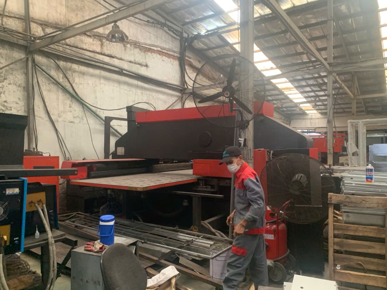
How Material Thickness Affects Die Wear
Die wear is driven by three main factors: the hardness of the material being stamped, the forming forces applied, and the number of hits (cycles) the die experiences. Thickness interacts with all three.
When you go thinner, the blank is lighter and requires less gross tonnage to cut and form. That sounds like it should reduce wear. But there are counteracting effects:
- Tighter die clearances. Thinner materials need tighter punch-to-die clearances. Tighter clearances concentrate stress on the cutting edges, accelerating edge wear.
- Higher precision demands. Thinner parts require more precise alignment. Misalignment causes uneven wear patterns.
- Potential for higher-strength substitutes. When designers go thinner, they sometimes compensate by switching to a higher-strength alloy. Harder materials are more abrasive on die surfaces.
Thickness, Material, and Tool Life Interaction
| Scenario | Effect on Tool Life | Why |
|---|---|---|
| Thinner gauge, same material | Slightly reduced | Tighter clearances concentrate edge stress |
| Thinner gauge, harder material | Significantly reduced | Higher abrasion from hard alloy + tight clearance |
| Thinner gauge, softer material (e.g., aluminum) | Neutral to improved | Lower forming forces, less abrasion |
| Thicker gauge, same material | Slightly improved edge life | Larger clearances, but higher gross tonnage |
Tooling Maintenance Strategy
The right response to a gauge change is not to accept faster die wear — it is to adjust the tooling and maintenance plan. Here is what I recommend:
- Re-cut die clearances when changing gauge. The clearance should typically be 5–10% of material thickness per side.
- Upgrade die steel if switching to a harder stamped material. D2 or carbide inserts last significantly longer against stainless and high-strength alloys.
- Increase sharpening frequency for the first few production runs until you establish a new wear curve.
- Track hits per sharpening and compare to baseline. This data tells you exactly how the gauge change affected tool life.
Long-term maintenance expenses depend more on how well the tooling was matched to the material than on the thickness alone. A well-designed die running a thinner, softer material can last hundreds of thousands of cycles. A poorly matched die running a hard alloy at a thin gauge might need rework after 20,000 hits.
Early Collaboration Prevents Surprises
This is exactly why the trend toward early engineer collaboration exists. When our team reviews a project before tooling is cut, we evaluate not just whether the part can be made, but how the material-gauge combination will affect long-term tooling costs. We factor in material hardness, part geometry complexity, expected production volume, and maintenance intervals. This upfront analysis prevents the kind of surprise die failures and unplanned maintenance costs that erode a project's profitability over time.
Conclusion
There is no single best material thickness for stamping parts. The right gauge balances your part's functional demands, material properties, tooling requirements, and total production cost — without overengineering.
Frequently Asked Questions
How do I determine the optimal material thickness to balance part durability with my project budget?
A few months ago, a U.S. client sent us drawings for a set of mounting brackets. The original spec called for 2.5 mm carbon steel 2 . After our engineering team reviewed the load requirements, we found that 1.5 mm met every structural demand — saving the client over 15% on material cost across a 20,000-unit run.
What are the risks to my stamping quality if I reduce material thickness to save on production costs?
During a recent project review, our quality team flagged a recurring issue: a client had switched from 1.2 mm to 0.8 mm stainless steel to cut costs, and the thinner gauge was cracking along tight bend radii during forming. The scrap rate jumped from under 2% to over 12% before we intervened with a design revision.
How can I ensure my offshore manufacturer maintains tight tolerances when I specify non-standard material gauges?
One of the toughest conversations I have with U.S. purchasing managers is about tolerances. They want ±0.002" on every dimension, but when we run the numbers, tightening beyond ±0.005" on a non-critical feature can increase tooling costs by 20–30% and slow production speed dramatically.
Footnotes
1. Explains the concept of designing products for efficient and cost-effective manufacturing processes. ↩︎
2. Provides information on the composition, properties, and common uses of carbon steel. ↩︎
3. Defines a critical mechanical property of materials, indicating resistance to breaking under tension. ↩︎
4. Defines the ability of a material to withstand damage from chemical or electrochemical reactions. ↩︎
5. Explains a critical engineering simulation technique used to predict material behavior under various forces. ↩︎
6. Details the properties, types, and applications of stainless steel, a common stamping material. ↩︎
7. Discusses the causes and effects of degradation on stamping dies, impacting tool life. ↩︎
8. Explains the phenomenon of elastic recovery in metal forming after bending forces are removed. ↩︎
9. Describes the standardized process for approving production parts, ensuring consistent quality. ↩︎
10. Provides an overview of the metal stamping process, emphasizing accuracy and repeatability. ↩︎