
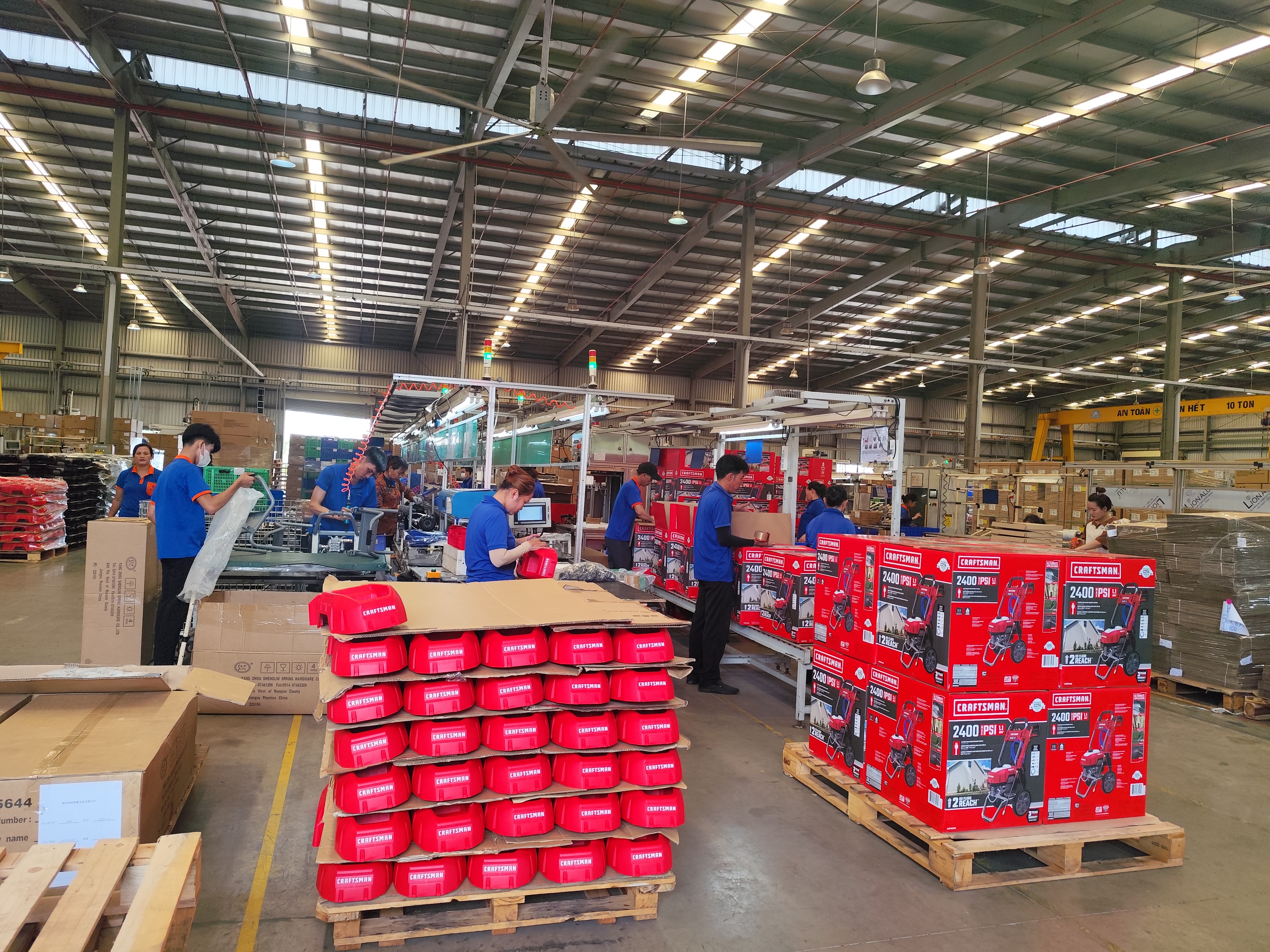
A shipment of mounting brackets arrived at our client’s warehouse last quarter — dimensionally perfect, but covered in visible scratches and inconsistent grain lines that made them unusable for a consumer-facing product.
To communicate appearance and aesthetic standards in sheet metal fabrication, explicitly define surface finish specifications, grain direction, scratch tolerance, and cosmetic defect limits on your drawings. Classify surfaces by visibility, provide visual reference samples, and engage fabricators early through design for manufacturability DFM reviews to prevent non-conforming results.
The gap between “functionally correct” and “visually acceptable” is where most sourcing disputes begin roughness average Ra values 1. This article breaks down the specific steps, standards, and communication strategies that prevent those disputes from happening in the first place.
How can I clearly define cosmetic requirements in my sheet metal drawings to avoid ambiguity?
One lesson our engineering team in Vietnam learned early: a drawing that says "smooth finish" means something different in every shop. The word "smooth" is not a specification. It is an invitation for interpretation — and interpretation is the root cause of cosmetic rejects.
Define cosmetic requirements on sheet metal drawings by specifying roughness average Ra values, grain direction, scratch and dent limits by zone, and a surface classification system (Class A through D). Include reference photos or golden samples, and call out each surface's cosmetic grade directly on the drawing views.
Your Drawing Is Your Voice
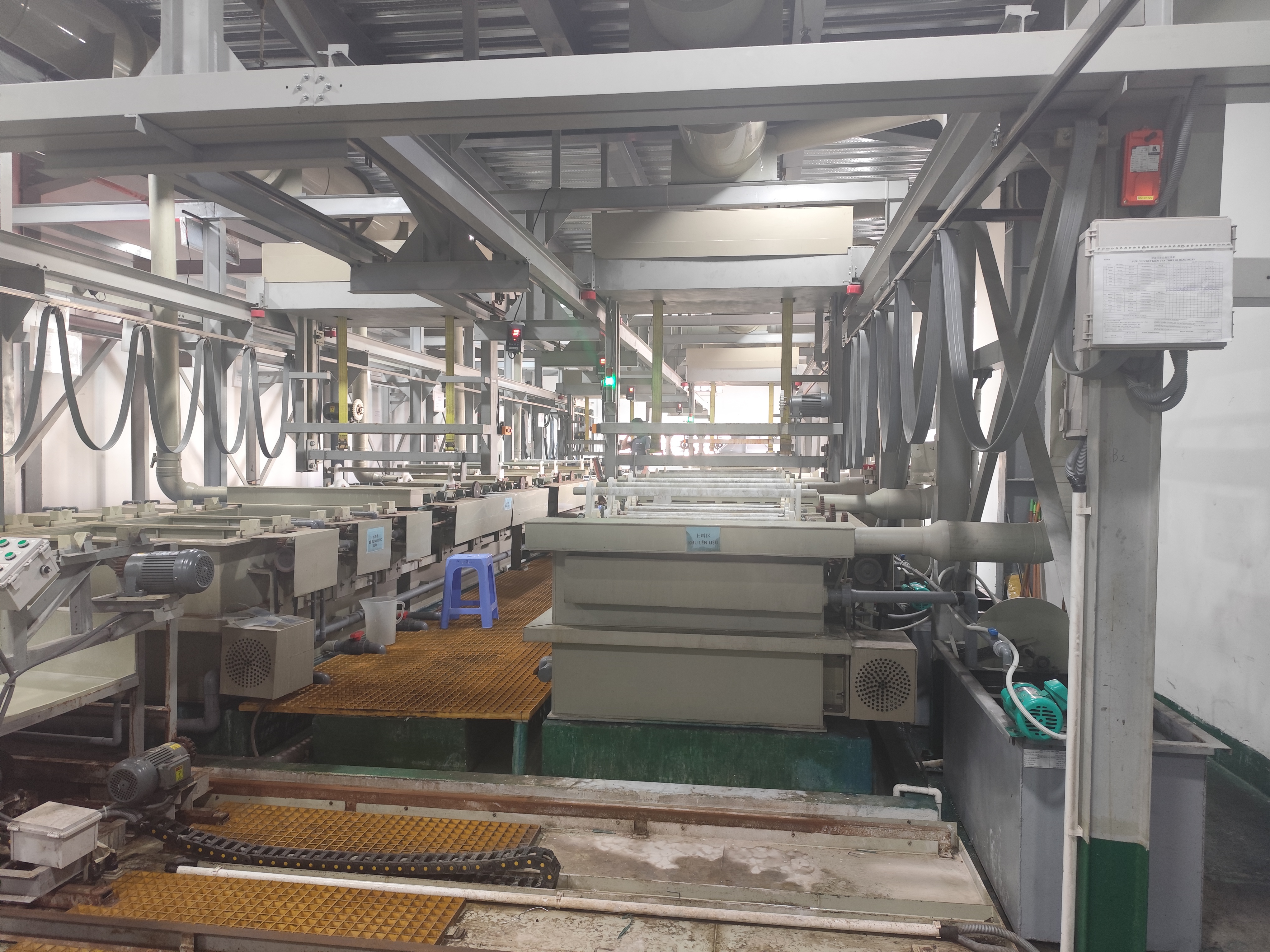
When we manage custom part programs for U.S. buyers, the drawing is the single most important communication tool. It travels across language barriers, time zones, and organizational layers. If cosmetic intent is not on the drawing, it does not exist for the shop floor operator.
Here is what must be explicitly stated:
- Grain direction: Indicate the direction of the brushed or rolled grain with arrows on each relevant view. A note like "grain direction must run parallel to the long axis" removes ambiguity.
- Surface roughness: Use Ra values. For a brushed stainless steel panel, Ra 0.8–1.6 µm is a common range. For a mirror polish, Ra below 0.1 µm. Do not rely on descriptive words alone.
- Scratch and dent tolerance: State the maximum allowable length, width, and depth of scratches, and the maximum number per defined area. For example: "No scratches deeper than 0.05 mm or longer than 10 mm on Class A surfaces."
Surface Classification System
Not every surface on a bracket or enclosure is visible to the end user. Treating all surfaces equally inflates cost and lead time. The industry-standard approach is to classify surfaces by cosmetic importance. surface classification system 2
| Surface Class | Visibility Level | Typical Requirements | Example |
|---|---|---|---|
| Class A | Primary visible surface | No visible defects at 300 mm under direct lighting. Controlled grain direction. Specified Ra value. | Front panel of an enclosure |
| Class B | Secondary visible surface | Minor imperfections acceptable. Grain direction preferred but not mandatory. | Side panel, partially visible |
| Class C | Rarely visible surface | Tool marks and minor scratches acceptable. No sharp edges. | Interior mounting surface |
| Class D | Non-visible / internal | Functional requirements only. No cosmetic criteria. | Hidden structural bracket |
Call out these classes directly on the drawing. Use color coding or hatching on the 3D model views to make it visually obvious which surfaces fall into which category. This approach directly addresses the surface roughness requirements by focusing resources where they matter.
Grain Direction Pitfalls
On a recent project involving mirrored mounting bracket pairs — similar to the angular, multi-fold brackets with gunmetal grey powder coat 3 that we regularly source — grain inconsistency between the left-hand and right-hand parts was the most common rejection reason. The grain ran vertically on one bracket and horizontally on the other. Functionally identical. Visually unacceptable when mounted side by side.
The fix was simple: add a grain direction arrow on every flat face of the drawing, and include a note stating "grain direction must be consistent across all parts in the assembly."
What visual inspection standards should I provide to ensure my supplier gets the finish right the first time?
During a supplier audit at a Vietnamese sheet metal shop last year, I watched an inspector hold a bracket under a fluorescent tube and approve it. The same part was later rejected by our client's incoming QC team, who inspected it under LED panel lights at a 45-degree angle. The part had not changed. The inspection conditions had.
Provide your supplier with a documented visual inspection standard that defines the lighting type and intensity (e.g., D65 daylight or 500 lux LED), the viewing distance (typically 300–500 mm), the inspection angle, the viewing duration per surface, and a set of limit samples showing the boundary between acceptable and rejectable cosmetic defects.

Why Inspection Conditions Matter More Than You Think
Quality control inspection for cosmetic defects is inherently subjective. Two trained inspectors can reach different conclusions about the same part if they inspect it under different conditions. The solution is to standardize every variable.
Here is a practical framework we use for our clients' programs:
| Inspection Variable | Recommended Standard | Why It Matters |
|---|---|---|
| Lighting | D65 daylight 4 simulation or 500+ lux LED, diffused | Fluorescent lighting hides fine scratches; harsh directional light exaggerates them |
| Viewing distance | 300 mm for Class A; 500 mm for Class B | Closer inspection reveals defects invisible at assembly distance |
| Viewing angle | Perpendicular to surface, then swept 15–45° | Angled viewing catches surface waviness and shallow dents |
| Duration | 5–10 seconds per surface zone | Too fast misses defects; too long causes fatigue-based over-rejection |
| Background | Neutral grey or white, non-reflective | Colored backgrounds alter perception of surface shade |
Golden Samples and Limit Samples
The most effective tool I have seen for aligning supplier expectations is a set of physical reference samples. These are actual parts — not photos — that represent:
- Golden sample: The ideal result. This is the target.
- Acceptable limit sample: The worst part that still passes. This defines the boundary.
- Reject sample: A part that fails. This shows what is not acceptable.
Ship these samples to the supplier before production begins. Have the supplier's QC team sign off on them. Reference them in the drawing notes: "Visual inspection per limit samples dated [date], retained at supplier facility." This removes subjective judgment from the equation and gives the inspector a physical benchmark.
The Role of AI and Digital Tools
Some fabricators are now integrating AI-powered visual inspection systems 5 that use cameras and machine learning to detect cosmetic defects consistently across shifts. These systems compare each part against a digital reference and flag deviations. For high-volume production runs, this technology reduces the variability inherent in human visual inspection criteria.
Even without AI, digital twin technology and advanced 3D rendering allow buyers to validate aesthetic standards virtually before committing to tooling. We have used CAD renderings to confirm grain orientation and surface break lines with clients before cutting a single piece of metal.
How do I communicate specific surface finish expectations to prevent non-conforming aesthetic results?
A trade-off we weigh on nearly every custom project: which finishing process delivers the right look without blowing the budget or the delivery date? The answer depends on the material, the geometry, and — critically — on how clearly the expectation is communicated.
Communicate surface finish expectations by specifying the exact finishing process (e.g., #4 brushed, bead blast at 80–120 grit, powder coat to RAL color), the required roughness average Ra, and any pre-finish surface preparation. State whether the finish is applied before or after forming, and note that finishes often highlight rather than hide existing surface flaws.
Finishes Highlight Flaws — They Do Not Hide Them
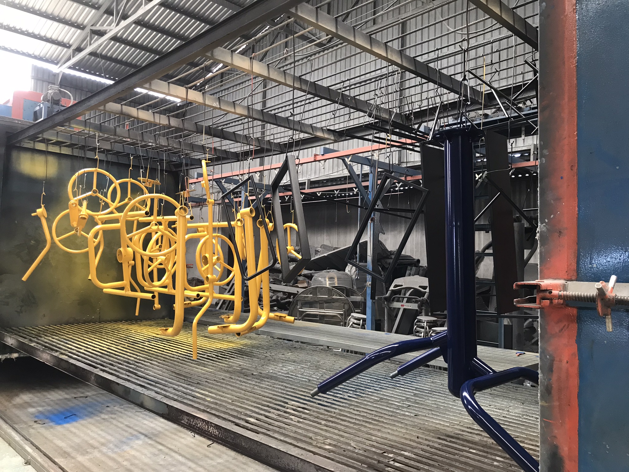
One of the most persistent myths in sheet metal sourcing is that a coat of paint or powder will cover up scratches, dents, and grain inconsistencies. The opposite is true. Glossy powder coatings act like a magnifying lens over surface imperfections. A scratch that is barely visible on raw steel becomes a prominent line under a gloss black finish.
This is why finishing processes must be considered at the design stage, not as an afterthought. The surface preparation before coating — degreasing, phosphating, blasting — and the coating thickness all interact with the base metal condition.
Matching the Finish to the Material
Material selection has a direct impact on achievable surface finish quality. Stainless steel in a 2B mill finish provides a clean, consistent base for further polishing or brushing. Carbon steel requires more aggressive surface prep and is more susceptible to corrosion-related discoloration if not sealed quickly after finishing.
| Material | Common Finish Options | Aesthetic Consideration | Formability Note |
|---|---|---|---|
| 304 Stainless Steel 6 | #4 Brushed, #8 Mirror, Electropolish, Passivation | Excellent base for high-cosmetic finishes. Grain direction critical. | Good formability; minimum bend radius 1x material thickness |
| 1018 Carbon Steel | Powder coat, Zinc plating, E-coat, Paint | Must be coated to prevent corrosion. Surface prep quality determines finish quality. | Good formability; watch for scale after laser cutting |
| 5052 Aluminum | Anodize (Type II/III) 7, Powder coat, Chromate conversion | Anodizing provides durable cosmetic finish. Color consistency requires batch control. | Excellent formability; minimum bend radius 1x thickness |
| Galvanized Steel | Powder coat over zinc, Paint | Spangle pattern can telegraph through thin coatings. | Moderate formability; zinc can crack at tight bends |
The Dual-Material Strategy
For assemblies where only some surfaces are visible, a growing trend is the dual-material strategy: use a premium material like stainless steel for the visible exterior panels and a cost-effective material like carbon steel for hidden structural components. This balances appearance with budget. On a recent enclosure program, we specified 304 stainless for the front panel (Class A) and galvanized steel for the internal chassis (Class D), reducing material cost by approximately 30% without any compromise to the finished product's appearance.
Geometric Constraints That Affect Finish Quality
The geometry of the part directly affects how well a finish turns out. Tight bends can crack coatings. Deep embossments create thin spots in powder coat coverage. Holes placed too close to bends cause distortion that shows through the finish.
According to industry design guidelines from Approved Sheet Metal, holes should be placed at least 3x material thickness from bends to prevent distortion. For materials thinner than 0.036 inches, holes should be at least 0.062 inches from any edge. For thicker stock, this minimum increases to 0.125 inches. Interior bend radius should be at least equal to the material thickness — going tighter risks cracking that becomes visible after coating. Embossment depth should not exceed 50% of sheet thickness to avoid stress concentrations that cause localized finish failures.
These dimensional tolerances and geometric constraints are not just functional concerns. They are aesthetic concerns, because every forming defect becomes a visible defect once the finish is applied.
Finish Timing and Lead Time
Finishing adds time to the production schedule. Powder coating typically requires 1–3 days for batch processing, plus curing time. Anodizing can take 3–5 days depending on the anodizer's queue. Plating processes vary widely. Communicate your delivery date requirements alongside your finish specifications so the fabricator can plan the production sequence. A common mistake is to finalize the fabrication schedule without accounting for finishing lead time, which pushes the delivery date and creates friction with the supplier.
What steps can I take to ensure my offshore supplier understands the difference between functional and aesthetic surfaces?
A buyer interaction last quarter brought this issue into sharp focus. Our client sent a drawing package for a set of heavy-duty angular mounting brackets — parts with multiple folds, sharp bends, and pre-drilled mounting holes, similar to the gunmetal grey powder-coated components we regularly manage. The drawing was technically complete. Every dimension was toleranced. But nowhere did it indicate which surfaces were visible in the final assembly and which were hidden behind panels. The supplier treated every surface identically, spending time and money polishing internal flanges that no one would ever see.
Ensure your offshore supplier distinguishes functional from aesthetic surfaces by marking each surface zone on the drawing with a cosmetic class (A through D), holding a pre-production DFM review to walk through assembly context, providing photos or renderings of the part in its installed position, and establishing direct communication channels for real-time clarification of aesthetic intent.
Collaborate Early, Not Late
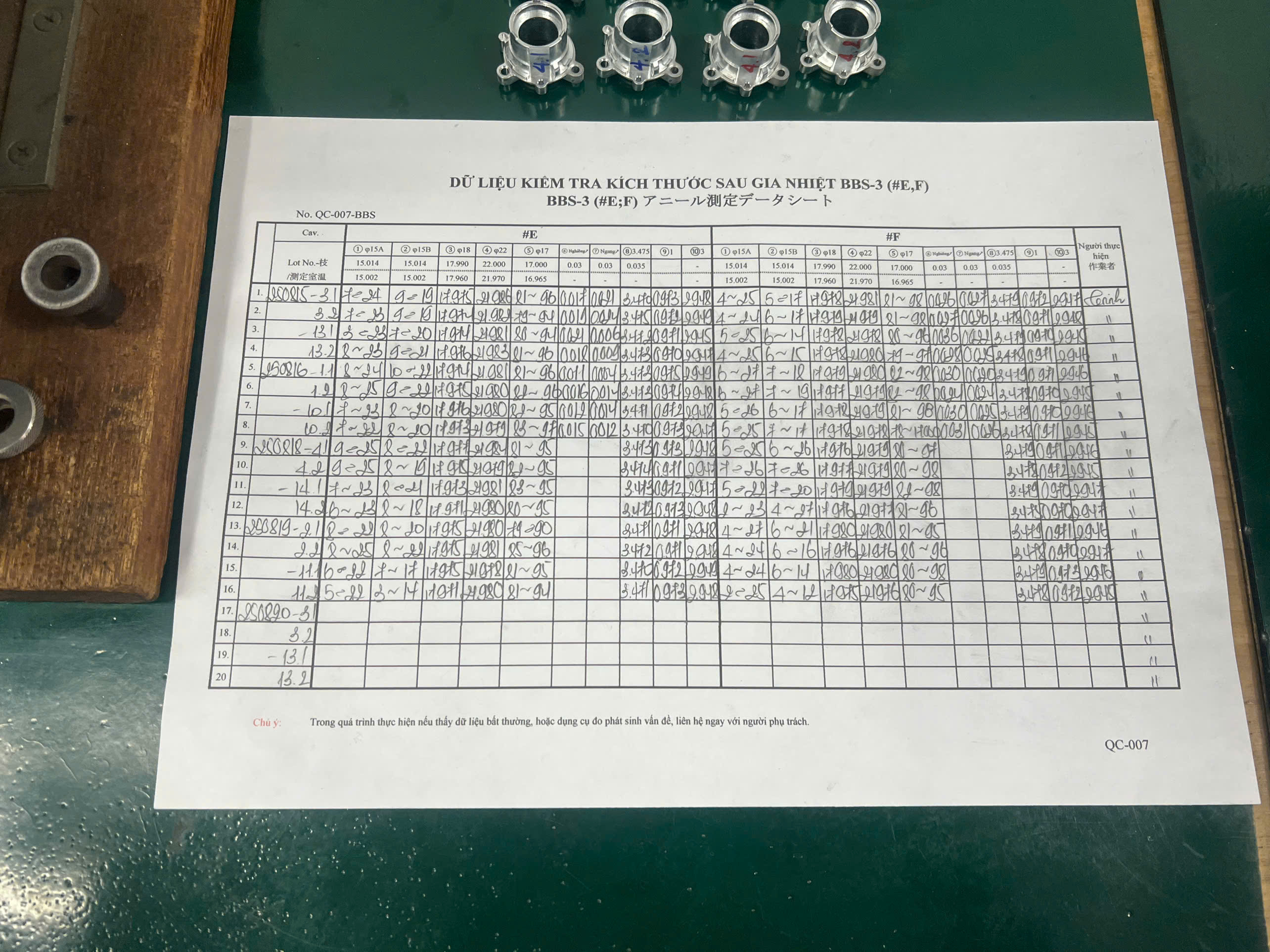
The most expensive words in custom manufacturing are "I assumed you knew." Waiting until the design is finalized to consult the fabricator leads to redesigns, delays, and non-conforming parts. Early DFM reviews — conducted while the design is still flexible — allow the fabricator to flag potential cosmetic issues before tooling is committed.
In our process at DEWIN, we schedule a formal DFM review with the fabricator within the first week of receiving a new drawing package. This review covers:
- Which surfaces are Class A and which are Class D
- Whether the proposed bend radii and hole placements support the required finish quality
- Whether the material selection aligns with both formability and appearance goals
- Whether the tolerancing strategy is functional or blanket
The Tolerance Truth
A common assumption among designers is that tight dimensional tolerances everywhere ensure a high-quality part. Industry experts argue the opposite. Blanket tight tolerances increase cost, extend lead time, and cause unnecessary rework — without adding value on non-critical features.
The modern approach is functional tolerance review 8: identify the dimensions that truly matter for fit, function, or appearance, and tolerance those tightly. Relax everything else. For sheet metal, a height tolerance of ±0.012 inches is typical for formed features. Flange lengths should be a minimum of 4x material thickness. Hem return lengths should be 6x material thickness. Notches and tabs must be at least equal to material thickness or 0.04 inches, whichever is greater, and no longer than 5x their width.
This tolerance strategy saves money and reduces the rejection rate, which directly supports on-time delivery — a critical pain point for U.S. purchasing managers sourcing from Asia. For a deeper look at this topic, see how to communicate OEM tolerance requirements to sheet metal fabrication suppliers.
Supplier Communication Best Practices
Effective supplier communication best practices for offshore sourcing include:
- Direct channels for urgent issues: A dedicated WeChat, WhatsApp, or Teams contact for the project engineer, not a general sales inbox.
- Scheduled updates for milestones: Weekly or bi-weekly video calls during production to review progress photos and address emerging issues.
- Assembly context documentation: Provide photos, renderings, or even short videos showing where each part sits in the final assembly. This gives the fabricator context that a 2D drawing cannot convey.
- Written acknowledgment of cosmetic requirements: Before production begins, have the supplier's quality team sign a document confirming they understand the surface classification, inspection criteria, and limit samples.
Standardization Reduces Risk
Standardizing features across a product family — uniform hole sizes, consistent flange lengths, common bend radii — simplifies tooling and reduces the chance of cosmetic variation between parts. When every bracket in an assembly uses the same 6 mm mounting holes and the same 1.5x-thickness bend radius, the fabricator can optimize their setup and deliver consistent results. This is a practical application of design for manufacturability DFM 9 that pays dividends in both quality and cost.
The long-term aesthetic durability of the chosen finish also deserves early discussion. A finish that looks perfect out of the box but degrades under UV exposure or abrasion in the field creates warranty problems. Specify the service environment — indoor/outdoor, temperature range, chemical exposure — alongside the cosmetic requirements so the fabricator and finisher can recommend appropriate industry quality standards and coating systems.
Conclusion
Communicating appearance and aesthetic standards in sheet metal fabrication 10 requires explicit drawing callouts, standardized inspection criteria, early DFM collaboration, and clear distinction between functional and cosmetic surfaces — because precision in communication prevents costly rework.
Frequently Asked Questions
How can I clearly define cosmetic requirements in my sheet metal drawings to avoid ambiguity?
One lesson our engineering team in Vietnam learned early: a drawing that says "smooth finish" means something different in every shop. The word "smooth" is not a specification. It is an invitation for interpretation — and interpretation is the root cause of cosmetic rejects.
What visual inspection standards should I provide to ensure my supplier gets the finish right the first time?
During a supplier audit at a Vietnamese sheet metal shop last year, I watched an inspector hold a bracket under a fluorescent tube and approve it. The same part was later rejected by our client's incoming QC team, who inspected it under LED panel lights at a 45-degree angle. The part had not changed. The inspection conditions had.
How do I communicate specific surface finish expectations to prevent non-conforming aesthetic results?
A trade-off we weigh on nearly every custom project: which finishing process delivers the right look without blowing the budget or the delivery date? The answer depends on the material, the geometry, and — critically — on how clearly the expectation is communicated.
Footnotes
1. Details the definition, measurement, and importance of Ra values in surface finish specifications. ↩︎
2. Describes common surface classification systems (Class A, B, C, D) used for cosmetic requirements. ↩︎
3. Replaced HTTP 403 link with an authoritative Wikipedia article explaining powder coating. ↩︎
4. Explains the D65 standard illuminant for consistent color and appearance evaluation. ↩︎
5. The original Google Cloud blog post, which was previously inaccessible due to HTTP unknown, is now working and directly addresses AI-powered visual inspection systems. ↩︎
6. Details the properties, corrosion resistance, and common uses of 304 stainless steel. ↩︎
7. Explains the differences and applications of Type II and Type III anodizing processes for aluminum. ↩︎
8. Describes functional tolerance analysis and its role in ensuring product performance and robust design. ↩︎
9. Replaced HTTP 404 link with an authoritative Wikipedia article explaining Design for Manufacturability. ↩︎
10. Replaced HTTP unknown link with a comprehensive industry guide on sheet metal fabrication. ↩︎