Burr control requirements sank one of our early stamping projects. The drawing said “no burrs.” The supplier shipped parts anyway. Our client’s assembly line rejected every carton, and the rework bill was painful.
To communicate burr control requirements to stamping parts suppliers, specify a measurable maximum burr height (typically 5–10% of sheet thickness), mark burr direction and critical edges on drawings, reference standards like ISO 13715, and define the exact inspection method before tooling is built.
That is the short answer. But each of those steps has details that decide whether your parts pass or fail. Let me walk through them one by one, based on what actually works in real sourcing projects.
What details should I include in my drawings to clearly define burr limits?
A buyer once sent our team in Vietnam a drawing with a single note: "clean edges required." Our engineers sent back three questions before quoting, because that phrase means nothing measurable.
Your drawings should include a numeric maximum burr height in millimeters, the required burr direction, marked critical edges and holes, edge break specifications for touch surfaces, and the material thickness the limit is based on. Never write vague notes like "no burrs" or "clean edges."
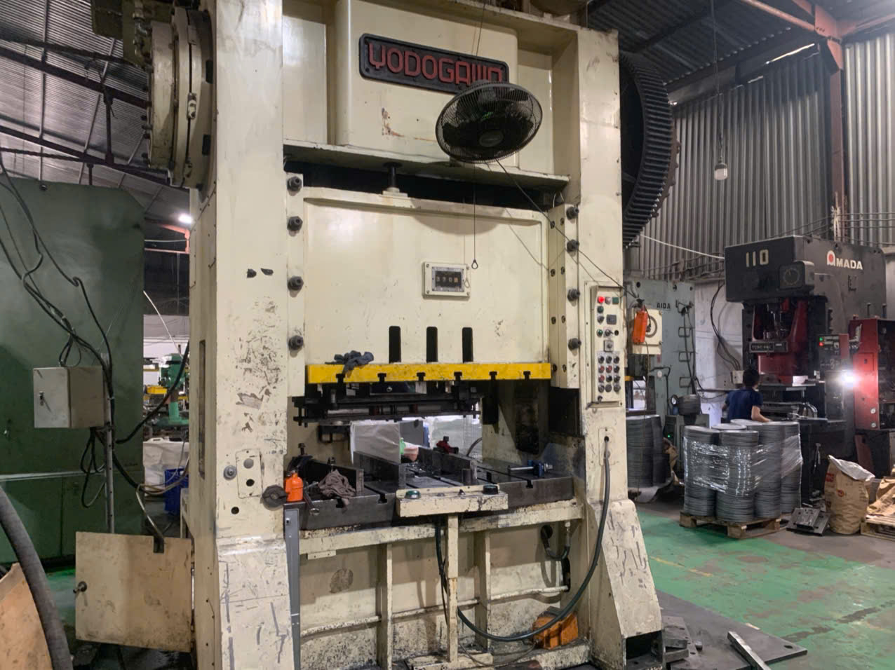
A stamping die always produces some burr. Physics guarantees it. The punch shears the material partway, then the material fractures the rest of the way. This material shear-to-break ratio 1 determines edge quality, and no supplier can promise a perfectly burr-free edge at a normal price. So your drawing must define what is acceptable, not demand the impossible.
Start with a numeric burr height limit
The industry baseline is 5–10% of sheet thickness. Here is the guide we share with clients when they draft their RFQs:
| Sheet Thickness | Typical Max Burr Height | Tight Requirement (automotive/precision) |
|---|---|---|
| ≤ 1.0 mm | ≤ 0.05 mm | ≤ 0.03 mm |
| 1.0–2.0 mm | ≤ 0.08 mm | ≤ 0.05 mm |
| 2.0–3.0 mm | ≤ 0.10 mm | ≤ 0.08 mm |
| > 3.0 mm | ≤ 0.15 mm | ≤ 0.10 mm |
Tighter is not always better. Every step tighter adds tooling cost 2, maintenance cost, and possibly a secondary deburring operation. Match the limit to the function.
Specify burr direction
Burr height limits alone are not enough. A 0.08 mm burr on a mating surface can still block assembly. Add a note such as "burr side away from datum A" or "burrs toward non-visible side." On our brackets with folded flanges and punched mounting holes, burr direction decides whether a bolt head seats flat or rocks on a raised edge.
Mark critical versus non-critical edges
Do not apply the tightest limit everywhere. Circle the functional edges — mating faces, slots, terminal contacts, weld zones — and allow looser limits elsewhere. This one habit can cut your quoted price meaningfully because the supplier only adds deburring effort where it matters. Also add edge break specifications for any surface an operator will handle by hand, such as "break sharp edges, max 0.2 mm chamfer permissible."
State the "why" on the drawing
A short functional note like "edge welds to mating panel" or "burr causes plating peel" helps the supplier choose the right die clearance specifications instead of guessing.
How can I verify my supplier truly understands my burr control standards?
Before we place any custom parts order, our project team runs a simple test: we ask the stamper to explain our burr requirement back to us in their own words. The answers are revealing.
Verify understanding by requiring the supplier to restate your burr limits in their quotation, review their die clearance and tooling plan before tooling starts, approve first-article samples against your spec, and sign quality assurance agreements that name burr height and direction explicitly.

Confirmation is not a signed drawing. Plenty of suppliers stamp "approved" on a drawing they never fully read. Real verification happens in stages, and each stage catches a different kind of misunderstanding.
Use a staged confirmation process
- Quotation stage. Ask the supplier to list your burr height limits and burr direction in their quote. If they only quote price and lead time, they have not engaged with the spec.
- Pre-tooling review. Request their planned die clearance specifications. For most steels, clearance runs 5–10% of material thickness 3 per side. A supplier who cannot explain their clearance choice for your material and temper is guessing.
- First article inspection. Require measured burr heights on the FAI report, not just a checkbox. Our inspectors in Vietnam photograph the burr side under magnification and attach readings to the report.
- Limit samples. Agree on physical boundary samples — one acceptable part, one rejectable part — signed by both sides. A visual limit board settles subjective arguments fast.
- Ongoing controls. Ask how tooling maintenance protocols are scheduled. Dull punches are burr magnets. A supplier with a tool-sharpening schedule tied to stroke counts will stay consistent across a long production run; one who sharpens "when parts look bad" will not.
Ask questions that expose real capability
We keep a short list of questions for supplier audits. How do you set punch-to-die clearance for stainless versus mild steel? At what stroke count do you inspect punches? What deburring method requirements can you support in-house — tumbling, brushing, manual? What happens to burr height as the die wears? Vague answers on any of these predict quality problems later.
Put the agreed limits into your quality assurance agreements 4, not just the drawing. Drawings define the part; agreements define the consequences when the part fails.
What inspection methods should I request to confirm burr requirements are met?
A U.S. purchasing manager we work with once rejected a shipment based on fingertip feel alone, while the supplier insisted the parts measured within limits. Both were "right" — because no inspection method had been agreed upfront.
Request burr height measurement with a profilometer, micrometer, or optical comparator on marked critical edges, a defined sampling plan per lot, go/no-go functional gauges for assembly-critical features, and signed limit samples for visual checks. Specify the method in the PPAP or control plan.

The method must match the tolerance. You cannot verify a 0.05 mm burr height limit by eye, and you do not need a profilometer to check a hand-safe edge break. Here is how we map inspection measurement techniques to requirement types in our final inspection work:
| Requirement Type | Recommended Method | Typical Use Case |
|---|---|---|
| Burr height ≤ 0.05 mm | Profilometer or toolmaker's microscope | Terminals, welded automotive edges |
| Burr height 0.05–0.15 mm | Optical comparator or point micrometer | General brackets, mounting clips |
| Burr direction | Visual check under 10x magnification | Mating and plated surfaces |
| Sharp edge / edge break | Fingertip or cotton-glove drag test against limit sample | Handled parts, consumer-adjacent hardware |
| Assembly interference | Go/no-go gauge or functional mating fixture | Slots, holes, snap-fit tabs |
Define the sampling plan, not just the tool
One measured part proves nothing about a 50,000-piece run. Ask for a stated sampling frequency 5, for example five parts per hour per cavity, or an AQL-based plan per lot. Burrs grow gradually as punches dull, so time-based sampling catches drift before it becomes a rejected shipment. Tie the sampling plan to the supplier's tooling maintenance protocols: measurements trending upward should trigger punch resharpening, not just a note in a logbook.
Make results traceable
Require the burr readings to appear on the outgoing inspection report with the measurement location identified. When our team performs pre-shipment final inspection 6, we mark the measured edges on a part photo so the client's incoming QC can repeat the exact same check. Repeatability is what prevents the "my gauge versus your gauge" argument at the receiving dock.
For assembly-critical holes and slots — like the punched round and oval holes on a stamped mounting clip — a simple go/no-go pin or a mating-fixture test often beats a height measurement, because it checks the burr's actual functional effect.
Which industry standards can I reference when specifying burr tolerances?
When our engineers prepare drawing packages for European and U.S. clients, we lean on published standards instead of inventing private definitions. Shared language removes half the arguments before they start.
Reference ISO 13715 for edge condition symbols on drawings, DIN 6784 for edge deviation definitions, and the 10% of material thickness rule of thumb as a baseline burr limit. For automotive programs, tie burr requirements into PPAP documentation and customer-specific standards.
Standards do two jobs. First, they give you precise symbols so a drawing note cannot be misread. Second, they give you leverage: a requirement backed by a recognized standard is harder for a supplier to dismiss as "too picky."
The standards worth knowing
| Standard / Reference | What It Covers | How to Use It |
|---|---|---|
| ISO 13715 | Edge condition symbols: burr permitted, burr-free, undercut, with size ranges | Add its edge symbols to drawing callouts for each critical edge |
| DIN 6784 | Edge deviation definitions (predecessor concepts to ISO 13715) | Useful with German-influenced suppliers and legacy drawings |
| 10% rule of thumb | Max burr height as a percentage of sheet thickness | Baseline when no customer-specific limit exists |
| PPAP / APQP (AIAG) | Production part approval, control plans | Embed burr checks into control plan and FAI reports |
| ISO 2768 | General tolerances | Covers dimensional context but not burrs — do not rely on it for edges |
ISO 13715 standards 7 deserve special attention. The standard defines a simple edge symbol with a value: a positive value permits a burr up to that height, a negative value requires material removal (an edge break or chamfer) up to that depth. So "+0.1" means a burr up to 0.1 mm is allowed, while "-0.3" demands the edge be broken by up to 0.3 mm. That single symbol replaces a paragraph of ambiguous notes and works alongside your normal GD&T edge symbols and datum structure.
Standards set the floor, function sets the limit
A caution from experience: standards are a starting point, not a substitute for thinking. A burr within the 10% rule can still ruin a spot weld or cause electrical arcing 8 on a terminal. When function is critical, state the tighter limit explicitly and explain the risk. Suppliers respond to "burr interferes with welding" far better than to a number alone, because it tells them which lever to pull — clearance, lubrication, press precision, or a secondary deburring step.
Finally, write the referenced standard into your purchase order and quality assurance agreements, not only the drawing. Contracts get read when drawings get skimmed.
Conclusion
Vague notes create burr disputes; measurable specs prevent them. Define height, direction, inspection, and standards before tooling — then verify with staged checks — and your stamped parts arrive right the first time.
Frequently Asked Questions
What details should I include in my drawings to clearly define burr limits?
A buyer once sent our team in Vietnam a drawing with a single note: "clean edges required." Our engineers sent back three questions before quoting, because that phrase means nothing measurable.
How can I verify my supplier truly understands my burr control standards?
Before we place any custom parts order, our project team runs a simple test: we ask the stamper to explain our burr requirement back to us in their own words. The answers are revealing.
What inspection methods should I request to confirm burr requirements are met?
A U.S. purchasing manager we work with once rejected a shipment based on fingertip feel alone, while the supplier insisted the parts measured within limits. Both were "right" — because no inspection method had been agreed upfront.
Footnotes
1. Wikipedia entry explaining the burnish (shear) and fracture (break) zones in metal blanking and piercing. ↩︎
2. Wikipedia entry detailing the manufacturing and cost factors associated with industrial stamping dies. ↩︎
3. Authoritative Wikipedia entry defining sheet metal thickness, gauge standards, and material properties. ↩︎
4. Wikipedia overview of quality assurance practices and formal agreements in manufacturing. ↩︎
5. NIST Engineering Statistics Handbook section on sampling plans and frequency in quality control. ↩︎
6. Comprehensive Wikipedia overview of the pre-shipment inspection process and its role in quality control. ↩︎
7. Official ISO standard for technical product documentation of edges with undefined shapes. ↩︎
8. Wikipedia explanation of electrical arcing, which can be caused by burrs on electrical terminals. ↩︎