
">
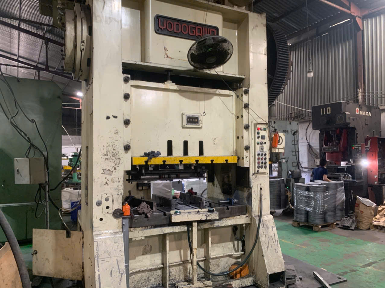
Installing [replacement stamping parts](https://dewintech.com/blog/what-individual-users-know-before-buying-replacement-stamping-parts/) sounds simple until a new part fails within days Lockout-tagout hardware 1. I have seen this cost our clients real money, and it almost always traces back to a rushed installation, not a bad part.
To correctly install replacement stamping parts, first verify the part matches specifications, then lock out the equipment, clean all mounting surfaces, seat the part in the correct orientation, check alignment before final tightening, run a slow test cycle, and inspect the first articles produced.
That is the short answer. Below, I break each stage down into practical steps you can follow on any shop floor.
What steps should I follow to correctly install replacement stamping parts?
A few years back, our Vietnam team traced a burr problem on a bracket order to a punch that had been installed backward. The part itself was perfect. The installation was not. That lesson shaped how we now brief every supplier we audit.
Follow seven steps: confirm the replacement part against its spec sheet, de-energize and lock out the press, remove the worn part, clean the mounting area, install the new part in the correct orientation and seating depth, hand-tighten fasteners in sequence, then verify alignment before final torque.

I want to stress one idea before anything else. Installing a replacement stamping part is a quality-control job 2, not just a mechanical swap. When we manage contract manufacturing projects for U.S. buyers, we treat the moment of installation as the point where precision is either restored or lost. A stamped bracket, punch, die button, bushing, or guide insert only performs as designed if it sits exactly where the tool designer intended.
The Full Installation Sequence
Here is the sequence our process-control checklists follow. Each step exists because skipping it has caused a real failure somewhere.
| Step | Action | Why It Matters |
|---|---|---|
| 1 | Verify part number, dimensions, and hardness | A wrong or out-of-spec part fails no matter how well you install it |
| 2 | Lock out and tag out the press | Prevents accidental activation and injury |
| 3 | Remove the old part carefully | Forcing removal can damage seats and bores |
| 4 | Clean mounting surfaces and bolt holes | Debris under a part changes seating depth and alignment |
| 5 | Seat the new part in correct orientation | Wrong rotation or facing causes interference and burrs |
| 6 | Hand-thread fasteners first, then tighten in sequence | Even clamping load keeps the part square |
| 7 | Check alignment, then apply final torque | Final tightening locks in whatever position exists at that moment |
Notice that only one step involves actually placing the part. Everything else is verification and preparation. In our experience, teams that rush steps 1 and 4 create most of the problems that show up later as bad parts, binding, or premature wear. The physical swap takes minutes. Getting it right the first time is what saves the downtime.
How do I verify fit and alignment before installing stamping parts?
One of our long-term U.S. purchasing clients once asked me why we insist on bench inspection before any part touches a die. My answer was simple: it is far cheaper to reject a part on a bench than inside a running press.
Verify fit in three stages: bench-check the part's dimensions, hardness, and surface finish against the spec; test-fit it in the assembly to confirm seating depth, rotational orientation, and clearance; then close the die slowly without material to confirm free travel and zero interference.

Verification works best as a funnel. You start broad on the bench and finish narrow inside the tool. Each stage catches a different type of error, so none of them can be skipped.
Stage One: Bench Inspection
Before installation, measure the part against its drawing. We check critical dimensions with micrometers or an optical comparator. If hardness matters for the application, we confirm it. If surface finish affects performance, we confirm that too. Our final-inspection teams do this on every custom part shipment, because a dimension that is off by a few hundredths of a millimeter can ruin punch-to-die clearance.
Stage Two: Static Fit Check
Place the part into its seat without full tightening. Confirm three things. First, seating depth: the part must bottom out fully with no debris underneath. Second, rotational orientation: many punches and inserts only work one way. Third, clearance: punch-to-die clearance must match the design. Guide pins should travel freely through their bushings by hand.
Stage Three: Slow Closure Test
Close the die at inch speed with no material. Watch and listen. Punches should enter their openings cleanly. Nothing should bind, scrape, or resist. If anything feels wrong, stop and investigate before you ever run material.
| Verification Stage | What You Check | Typical Tools |
|---|---|---|
| Bench inspection | Dimensions, hardness, surface finish | Micrometer, optical comparator, hardness tester |
| Static fit check | Seating depth, orientation, clearance | Feeler gauges, pin gauges, dial indicator 3 |
| Slow closure test | Free travel, interference, entry alignment | Inch mode on press, visual and tactile check |
One more point. On high-speed presses, remember thermal expansion. A clearance set at room temperature may tighten once the tool reaches operating temperature, so plan clearances with the running condition in mind.
What tools and equipment do I need for proper stamping part installation?
When we audit new suppliers in Vietnam and across Asia, one of the first things I look at is their toolroom bench. The measuring equipment on that bench tells me more about their quality culture than any brochure.
You need three tool groups: safety equipment such as lockout-tagout devices; measurement instruments including micrometers, calipers, dial indicators, feeler gauges, and pin gauges; and installation tools such as a calibrated torque wrench, soft-faced hammer, cleaning supplies, and the manufacturer's spec sheet.
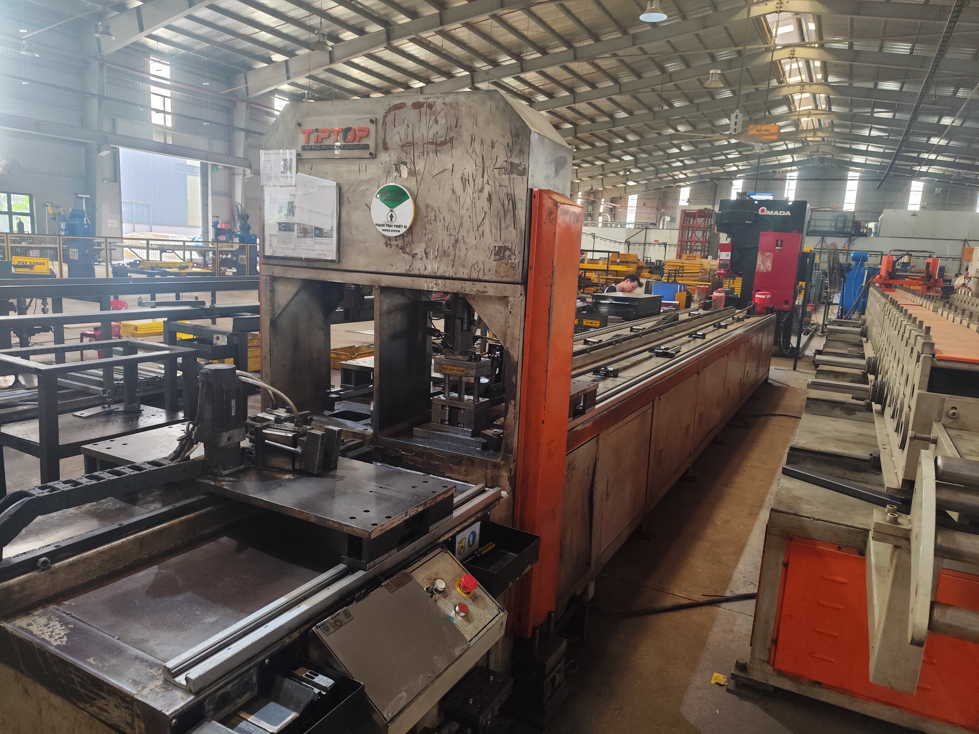
Good tools do not guarantee a good installation, but poor tools almost guarantee a bad one. Let me walk through each group and explain what it actually does for you.
Safety Equipment Comes First
Every installation starts with de-energizing the press. Lockout-tagout hardware 5, safety glasses, and cut-resistant gloves are non-negotiable. Stamped parts often have sharp die-cut edges, and a press that activates unexpectedly is a life-safety event, not just a quality problem.
Measurement Instruments Do the Real Work
This is where precision lives. A caliper handles general dimensions. A micrometer handles critical ones. A dial indicator confirms seating flatness and runout. Feeler gauges verify clearances. Pin gauges confirm hole sizes on punched features, like the round and slotted holes you see on typical stamped mounting brackets. For wear-related dimensions, an optical comparator or hardness tester adds another layer of confidence.
| Tool | Primary Use | When You Need It |
|---|---|---|
| Torque wrench | Applying specified fastener torque | Every installation with threaded fasteners |
| Micrometer | Critical dimension checks | Bench inspection before install |
| Dial indicator | Flatness, seating, runout | Static fit verification |
| Feeler gauges | Clearance measurement | Punch-to-die and gap checks |
| Pin gauges | Punched hole verification | First-article inspection |
| Lockout-tagout kit | Press de-energization | Before any work begins |
Installation Tools and Documentation
A calibrated torque wrench 6 matters because over-tightening distorts thin-gauge stamped parts and under-tightening lets them shift. A soft-faced hammer seats parts without marring surfaces. Lint-free cloths and solvent keep mounting faces clean. Finally, keep the drawing and torque spec at the bench. Our project managers insist on this because guessing at torque values is one of the quietest ways to ruin an otherwise perfect installation.
How can I avoid common installation errors that lead to part failure?
The most painful lesson in my sourcing career came from a shipment that measured perfectly at final inspection, yet still generated a complaint. The client's own team had forced the parts into misaligned mounting holes. Since then, we include installation guidance with certain custom orders.
Avoid failure by never forcing a part into position, never skipping surface cleaning, always confirming orientation before tightening, always using specified torque in the correct sequence, always running a slow test cycle, and always inspecting a first-article sample of five to twenty parts.

Most installation failures come from a small set of repeated mistakes. If you know them, you can build simple habits that prevent them.
The Six Errors I See Most Often
First, wrong orientation. A part that fits both ways mechanically may only work one way functionally. Check the drawing, not just the fit. Second, forcing a stuck part. If a part resists, something is wrong. Stop and find out what, because force hides the root cause and often damages the seat. Third, poor cleaning. A chip of debris under a mounting tab changes seating depth and throws off alignment across the whole tool. Fourth, incorrect seating depth. A part that has not fully bottomed out will shift under load. Fifth, wrong clearance. Insufficient punch-to-die clearance causes galling and chipping; excessive clearance causes burrs. Sixth, skipping the test run. Going straight to full production converts a small alignment error into a pile of scrap.
First-Article Inspection Closes the Loop
A replacement is not validated until it produces good parts under real conditions. Run a small sample, typically five to twenty pieces. Inspect burr height, hole location, edge quality, and surface condition. On our contract manufacturing projects, this first-article step 7 is written into the process-control plan, because it is the only proof that the installation actually worked.
Documentation Turns One Job Into a Baseline
Record your measurements, clearances, torque values, and first-article results. Photograph the installed part. This record becomes the baseline for future wear checks. The next time output quality drifts, you can compare against known-good numbers instead of guessing. Speed pressure on the floor is real, but a fifteen-minute documented verification is always cheaper than a shift of rework.
Conclusion
Correct replacement stamping parts installation is verification-first work. Confirm the spec, clean and align carefully, test slowly, inspect first articles, and document everything. Precision restored today prevents downtime tomorrow.
Frequently Asked Questions
What steps should I follow to correctly install replacement stamping parts?
A few years back, our Vietnam team traced a burr problem on a bracket order to a punch that had been installed backward. The part itself was perfect. The installation was not. That lesson shaped how we now brief every supplier we audit.
How do I verify fit and alignment before installing stamping parts?
One of our long-term U.S. purchasing clients once asked me why we insist on bench inspection before any part touches a die. My answer was simple: it is far cheaper to reject a part on a bench than inside a running press.
What tools and equipment do I need for proper stamping part installation?
When we audit new suppliers in Vietnam and across Asia, one of the first things I look at is their toolroom bench. The measuring equipment on that bench tells me more about their quality culture than any brochure.
Footnotes
1. OSHA’s lockout/tagout standard defines requirements for safely de-energizing presses before maintenance. ↩︎
2. ISO 9001 outlines quality management principles underlying installation as a control point. ↩︎
3. NIST calibration standards ensure precision instruments like dial indicators give accurate, traceable readings. ↩︎
4. Background on dial indicators supports their role in checking seating flatness and runout. ↩︎
5. OSHA defines lockout-tagout procedures that prevent accidental machine activation during maintenance. ↩︎
6. Explains how torque wrenches apply precise fastening force to prevent part distortion. ↩︎
{
“@context”: “https://schema.org”,
“@type”: “FAQPage”,
“mainEntity”: [
{
“@type”: “Question”,
“name”: “What steps should I follow to correctly install replacement stamping parts?”,
“acceptedAnswer”: {
“@type”: “Answer”,
“text”: “Follow seven steps: confirm the replacement part against its spec sheet, de-energize and lock out the press, remove the worn part, clean the mounting area, install the new part in the correct orientation and seating depth, hand-tighten fasteners in sequence, then verify alignment before final torque.”
}
},
{
“@type”: “Question”,
“name”: “How do I verify fit and alignment before installing stamping parts?”,
“acceptedAnswer”: {
“@type”: “Answer”,
“text”: “Verify fit in three stages: bench-check the part’s dimensions, hardness, and surface finish against the spec; test-fit it in the assembly to confirm seating depth, rotational orientation, and clearance; then close the die slowly without material to confirm free travel and zero interference.”
}
},
{
“@type”: “Question”,
“name”: “What tools and equipment do I need for proper stamping part installation?”,
“acceptedAnswer”: {
“@type”: “Answer”,
“text”: “You need three tool groups: safety equipment such as lockout-tagout devices; measurement instruments including micrometers, calipers, dial indicators, feeler gauges, and pin gauges; and installation tools such as a calibrated torque wrench, soft-faced hammer, cleaning supplies, and the manufacturer’s spec sheet.”
}
},
{
“@type”: “Question”,
“name”: “How can I avoid common installation errors that lead to part failure?”,
“acceptedAnswer”: {
“@type”: “Answer”,
“text”: “Avoid failure by never forcing a part into position, never skipping surface cleaning, always confirming orientation before tightening, always using specified torque in the correct sequence, always running a slow test cycle, and always inspecting a first-article sample of five to twenty parts.”
}
}
]
}