

Every week, our engineering team reviews drawings where a single design tweak could save thousands — yet the opportunity passes once production starts. Sheet metal fabrication costs 1 climb fast when designers overlook manufacturability.
Design changes reduce sheet metal fabrication costs by simplifying geometries, using standard material gauges, minimizing bends, applying only necessary tolerances, and consolidating parts. These design for manufacturability strategies can cut production expenses by 15–30% before a single part is ever made.
The biggest savings window opens during the CAD phase — not on the shop floor. Below, I walk through four practical design areas where our clients consistently unlock cost reductions on custom sheet metal projects.
How can I select standard material gauges to minimize my sheet metal fabrication expenses?
A lesson we learned early in our Vietnam facility: a client specified 2.5 mm stainless steel when 2 mm would have met every structural requirement. That single gauge change dropped their material cost by nearly 20%.
You minimize sheet metal fabrication expenses by selecting standard material gauges that are readily stocked by distributors, avoiding custom thickness orders, and choosing the thinnest gauge that still meets structural and functional requirements for your application.
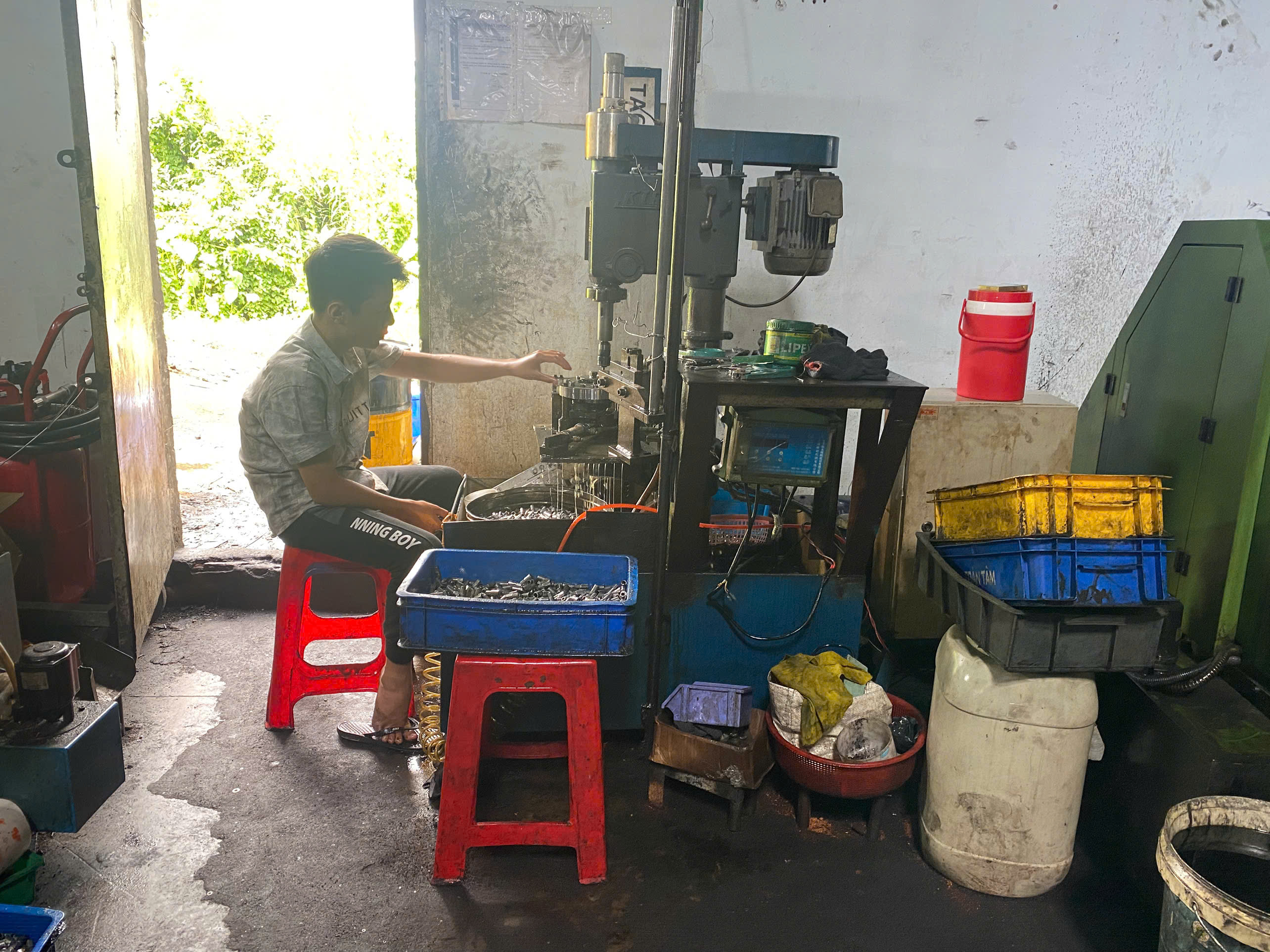
Why Standard Gauges Matter
Material selection is one of the first cost drivers in any sheet metal project. When you specify a non-standard sheet metal thickness, your fabricator must place a custom order. That means longer lead times, minimum order quantities, and premium pricing. Standard gauges are available from distributor stock. They ship faster. They cost less.
Here is a quick reference of commonly available gauges and their typical applications:
| Gauge | Thickness (mm) | Thickness (in.) | Common Applications |
|---|---|---|---|
| 20 | 0.91 | 0.036 | Enclosures, light brackets |
| 18 | 1.22 | 0.048 | General brackets, panels |
| 16 | 1.52 | 0.060 | Structural brackets, chassis |
| 14 | 1.90 | 0.075 | Heavy-duty frames, mounting plates |
| 12 | 2.66 | 0.105 | Industrial housings, structural components |
| 10 | 3.42 | 0.135 | Heavy structural applications |
Thinner Does Not Mean Weaker
Many engineers default to thicker material "just to be safe." But geometry provides structural integrity. A well-placed bend or rib stiffens a panel far more effectively than adding an extra millimeter of thickness. When we review drawings with our clients, we often find that reducing gauge by one step — say from 14 gauge to 16 gauge — delivers adequate strength while cutting raw material cost significantly.
Nesting Efficiency and Material Waste
Designing parts that fit standard sheet sizes also matters. Our production team arranges parts on standard sheets — typically 1220 mm × 2440 mm or 1000 mm × 2000 mm — to maximize nesting efficiency 2. If your part dimensions force awkward layouts, you waste material. Small adjustments to overall dimensions can reduce scrap by 20–30% with zero functional impact. We always recommend clients share their full part family so we can nest multiple part numbers on the same sheet.
Common Materials and Lead Times
Choosing common alloys — such as mild steel, 304 stainless, or 5052 aluminum — keeps costs low because these materials are always in stock. Exotic alloys or specialty finishes require custom sourcing, which inflates both price and delivery timelines. If your application does not specifically demand a specialty alloy, stick with the standards.
What design modifications can I implement to reduce the number of bends and lower my production costs?
During a recent project review, one of our U.S. clients submitted a bracket with eleven bends. After we walked through the functional requirements together, we brought that number down to six — and cut the forming cost almost in half.
You lower production costs by reducing the total number of bends, using a consistent bend radius throughout each part, orienting bends on the same plane, and eliminating bends that serve only aesthetic purposes without adding structural or functional value.
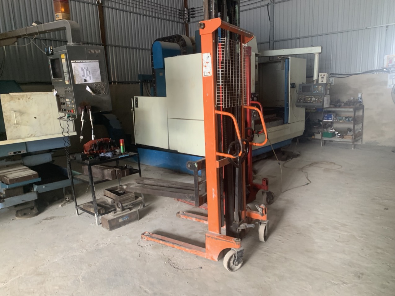
Every Bend Adds Time
Each bend requires a separate press brake operation. The operator must position the part, clamp it, form it, and inspect it. More bends mean more setups. When bends have different radii, the operator must also swap tooling — another time cost.
Here is how bend count affects relative forming cost:
| Number of Bends | Relative Forming Cost | Setup Complexity |
|---|---|---|
| 1–2 | Low | Single setup |
| 3–4 | Moderate | Minor repositioning |
| 5–7 | High | Multiple setups, possible tool changes |
| 8+ | Very High | Extensive repositioning, risk of tolerance stack-up |
Consistent Bend Radius Saves Money
Standardized tooling is the key phrase here. When every bend in your part uses the same radius — ideally 1 to 1.5 times the material thickness — your fabricator can form the entire part without changing the punch or die. A bend radius 4 of at least one times the sheet metal thickness also prevents fractures and distortions. We recommend this as a default rule on all our custom projects.
Bend Orientation and Access
Orienting bends on the same plane — so the press brake can form them in sequence without flipping or rotating the part — eliminates handling time. When bends fight each other directionally, the operator must reorient the workpiece repeatedly. Sometimes, a 180-degree part rotation adds two or three minutes per piece. On a run of 500 parts, that adds up fast.
Geometry Instead of Bends
Consider whether a bend is truly necessary. Sometimes a flat bracket with welded tabs performs the same function as a multi-bend bracket. Other times, two simple stampings joined with fasteners replace one complex formed part. The goal of design complexity reduction is not to strip away function — it is to achieve the same function with fewer operations.
Bend Relief and Deformation Prevention
Always include bend relief cuts at the intersection of bends and edges. Without them, the material tears or distorts. A relief notch should be at least one material thickness wide and extend slightly past the bend line. This small detail avoids scrap and rework.
How do my specified tolerances influence the final quote I receive for my custom metal parts?
One interaction with a client sticks with me. He submitted a drawing with ±0.05 mm on every dimension — even on non-critical flanges. When we explained how those tight tolerances tripled his inspection time and doubled his scrap risk, he was genuinely surprised.
Your specified tolerances directly influence your quote because tighter-than-necessary tolerances demand slower machining speeds, additional inspection steps, specialized fixturing, and higher scrap rates — all of which increase your per-part cost significantly.
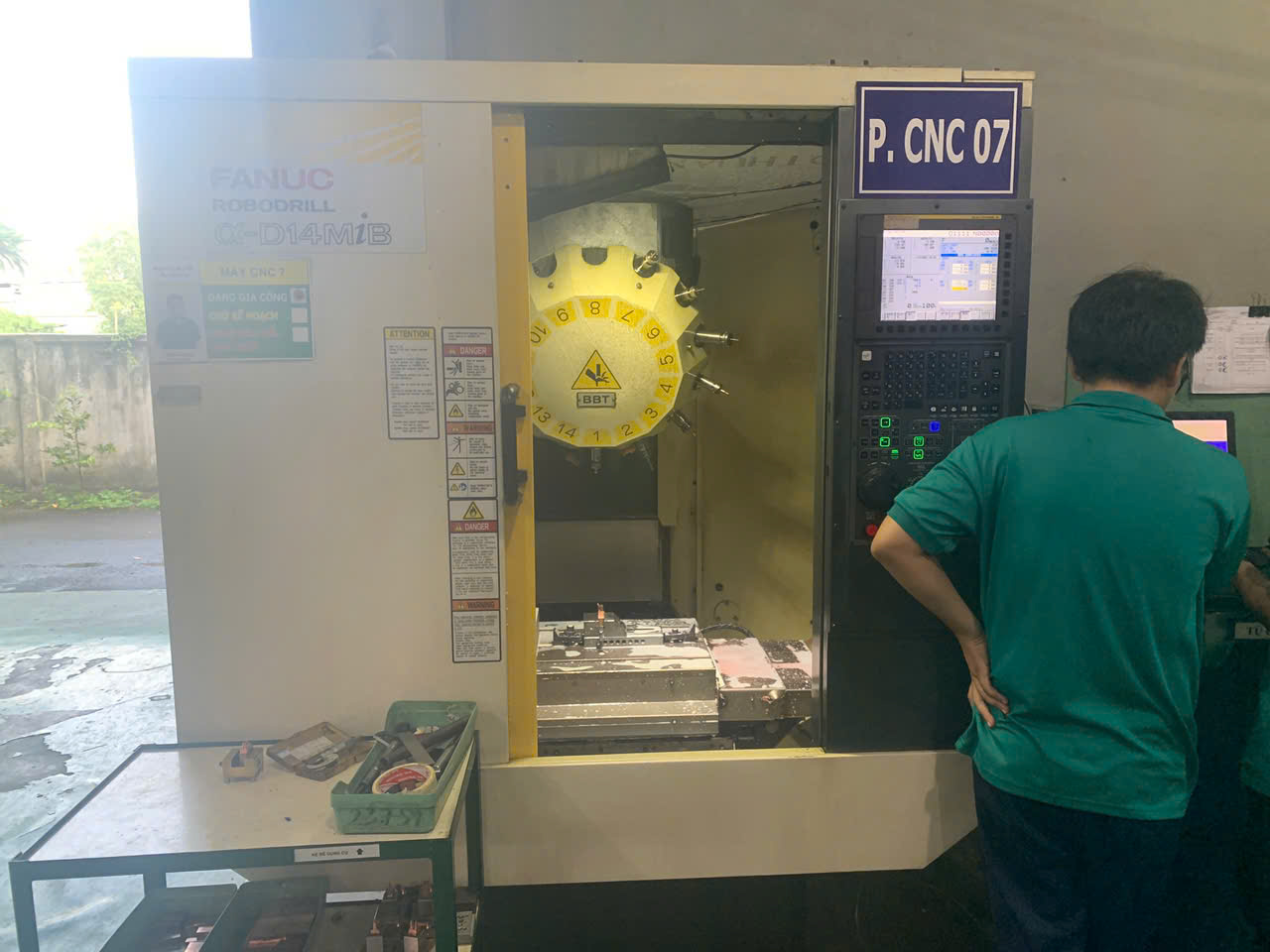
The Hidden Cost of Over-Tolerancing
Tight tolerances are sometimes essential — mating surfaces, bearing fits, and assembly interfaces may genuinely require ±0.1 mm or tighter. But applying that same precision to every hole, edge, and cutout creates unnecessary cost. Standard fabrication processes like laser cutting and CNC punching naturally hold ±0.25 mm or better. Specifying tighter than the process capability forces secondary operations, additional fixturing, and 100% dimensional inspection.
A Practical Tolerance Strategy
Here is a framework I share with our clients when they ask about tolerance strategy:
| Tolerance Level | Typical Range | When to Use | Cost Impact |
|---|---|---|---|
| Standard | ±0.25–0.50 mm | Non-critical dimensions, general edges | Baseline cost |
| Moderate | ±0.10–0.25 mm | Mating interfaces, bolt patterns | 10–25% premium |
| Tight | ±0.05–0.10 mm | Bearing fits, precision assemblies | 50–100% premium |
| Very Tight | < ±0.05 mm | Optical or medical-grade features | 150%+ premium |
The message is simple: apply tight tolerances only where the function demands it.
How Tolerances Affect Inspection and Rework
Every tight tolerance on your drawing becomes a measurement checkpoint in our quality control process. Our inspection team uses calibrated tools — CMMs, optical comparators, pin gauges — and each measurement takes time. When parts fall outside tolerance, they go to rework or scrap. Rework burns labor hours. Scrap burns material. Both drive your quote higher.
Aligning Tolerances with Process Capabilities
Different fabrication processes deliver different natural accuracies. Laser cutting holds tighter tolerances than plasma cutting. CNC bending is more precise than manual forming. When your hole design guidelines and edge tolerances align with the chosen process capability, you avoid paying for precision the process cannot deliver without secondary operations.
Our engineering team routinely reviews client drawings and flags dimensions where the tolerance is tighter than necessary. This single step — a tolerance audit — often saves 10–15% on the final quote.
Geometric Dimensioning and Tolerancing (GD&T) Tips
If you use GD&T, call out flatness, perpendicularity, and positional tolerances only on critical features. Geometric Dimensioning and Tolerancing 5 Leaving non-critical surfaces at default tolerance simplifies both manufacturing and inspection. This approach also reduces potential disputes during first article inspection (PPAP), which is a core part of our quality process at DEWIN.
Can I simplify my assembly design to decrease the overall welding and finishing time for my project?
A trade-off we weigh on nearly every project: weld it or fasten it? Welding creates a permanent joint, but it also demands skilled labor, post-weld grinding, and often re-finishing. The right joining methods can cut assembly time dramatically.
You decrease welding and finishing time by using self-locating tabs and slots, choosing mechanical fasteners over welds where possible, consolidating multiple parts into a single formed piece, and designing interlocking features that reduce or eliminate the need for manual welding.
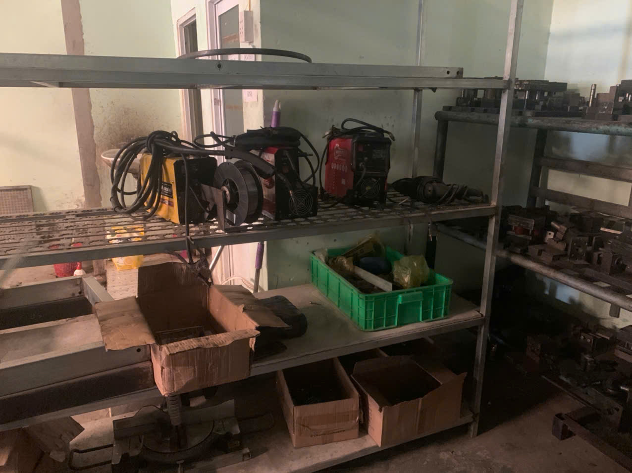
Part Consolidation: Fewer Parts, Lower Cost
One of the most powerful design for manufacturability 6 strategies is part consolidation 7. If two or three components are made from the same material and thickness, they can often be combined into a single flat pattern that folds into the final shape. This eliminates separate cutting operations, reduces inventory, and removes assembly steps entirely.
I recall a protective housing project where the original design had five separate panels welded together. Our team proposed a single-piece wrap-around design with integrated tabs. The result: four fewer welds, no panel alignment issues, and a 35% reduction in total assembly time.
Tabs, Slots, and Self-Locating Features
Designing tab-and-slot joints into your flat pattern serves two purposes. First, they locate parts precisely during assembly, eliminating the need for jigs or fixtures. Second, they reduce weld length — a tack weld at each tab is often all that is needed instead of a full seam weld.
Here is a comparison of common joining methods and their cost implications:
| Joining Method | Labor Intensity | Post-Processing Required | Best For |
|---|---|---|---|
| Full seam welding | High | Grinding, finishing | Structural, sealed joints |
| Tack welding with tabs/slots | Medium | Minimal grinding | Brackets, enclosures |
| PEM fasteners (press-fit) | Low | None | Removable panels, access doors |
| Rivets | Low | None | Permanent, non-structural joints |
| Interlocking tabs (no weld) | Very Low | None | Light-duty assemblies, prototypes |
Reducing Post-Processing Costs
Every weld creates a heat-affected zone and a visible bead. If the finished product requires a clean appearance, those welds must be ground, sanded, and re-finished. That post-processing costs money. When you replace welds with fasteners or interlocking features, you skip these finishing steps entirely. For painted or powder-coated parts, this also means less masking and fewer surface preparation steps.
Fastener Selection and Standardization
Using standard fastener sizes — M4, M5, M6 — across your assembly reduces procurement complexity and keeps hardware costs low. Press-fit fasteners like PEM nuts and studs can be installed during the fabrication process, so they arrive at assembly already in place. This eliminates hand-threading and speeds up the assembly line.
When Welding is the Right Choice
I do not suggest eliminating all welds. For high-stress structural joints, sealed enclosures, or pressure-rated assemblies, welding remains the best option. The key is to use welding only where the application demands it and to choose less labor-intensive joining methods everywhere else.
Design Review: The Biggest Cost Lever
Our team at DEWIN encourages clients to schedule collaborative design reviews at the concept phase — when design flexibility is highest. By the time a drawing is finalized and tooling is committed, the window for cost reduction narrows significantly. Early collaboration between the design engineer and the fabrication partner is where 80% of the savings are captured. We have seen projects where a single two-hour design review session identified changes that saved more than 25% of the total program cost.
Conclusion
Smart design changes — from standard gauges and fewer bends to practical tolerances and simplified assemblies — reduce sheet metal fabrication costs before production even begins. Start your next project with a collaborative design review to capture every savings opportunity.
Frequently Asked Questions
How can I select standard material gauges to minimize my sheet metal fabrication expenses?
A lesson we learned early in our Vietnam facility: a client specified 2.5 mm stainless steel when 2 mm would have met every structural requirement. That single gauge change dropped their material cost by nearly 20%.
What design modifications can I implement to reduce the number of bends and lower my production costs?
During a recent project review, one of our U.S. clients submitted a bracket with eleven bends. After we walked through the functional requirements together, we brought that number down to six — and cut the forming cost almost in half.
How do my specified tolerances influence the final quote I receive for my custom metal parts?
One interaction with a client sticks with me. He submitted a drawing with ±0.05 mm on every dimension — even on non-critical flanges. When we explained how those tight tolerances tripled his inspection time and doubled his scrap risk, he was genuinely surprised.
Footnotes
1. Provides insights into factors that influence sheet metal fabrication costs. ↩︎
2. Describes how nesting efficiency optimizes material utilization and reduces waste in sheet metal fabrication. ↩︎
3. Explains what standard material gauges are and their importance in metalworking. ↩︎
4. Replaced HTTP 404 link with a detailed guide on sheet metal bend radius guidelines from PEKO Precision Products, an authoritative manufacturing source. ↩︎
5. Defines GD&T as a standardized language for engineering tolerances and design intent. ↩︎
6. Introduces Design for Manufacturability (DFM) as a strategic approach to optimize product development. ↩︎
7. Explains part consolidation as a strategy to simplify designs and reduce manufacturing complexity. ↩︎
8. Replaced HTTP 404 link with an overview of mechanical fastening methods and applications from TWI (The Welding Institute), a highly authoritative source. ↩︎