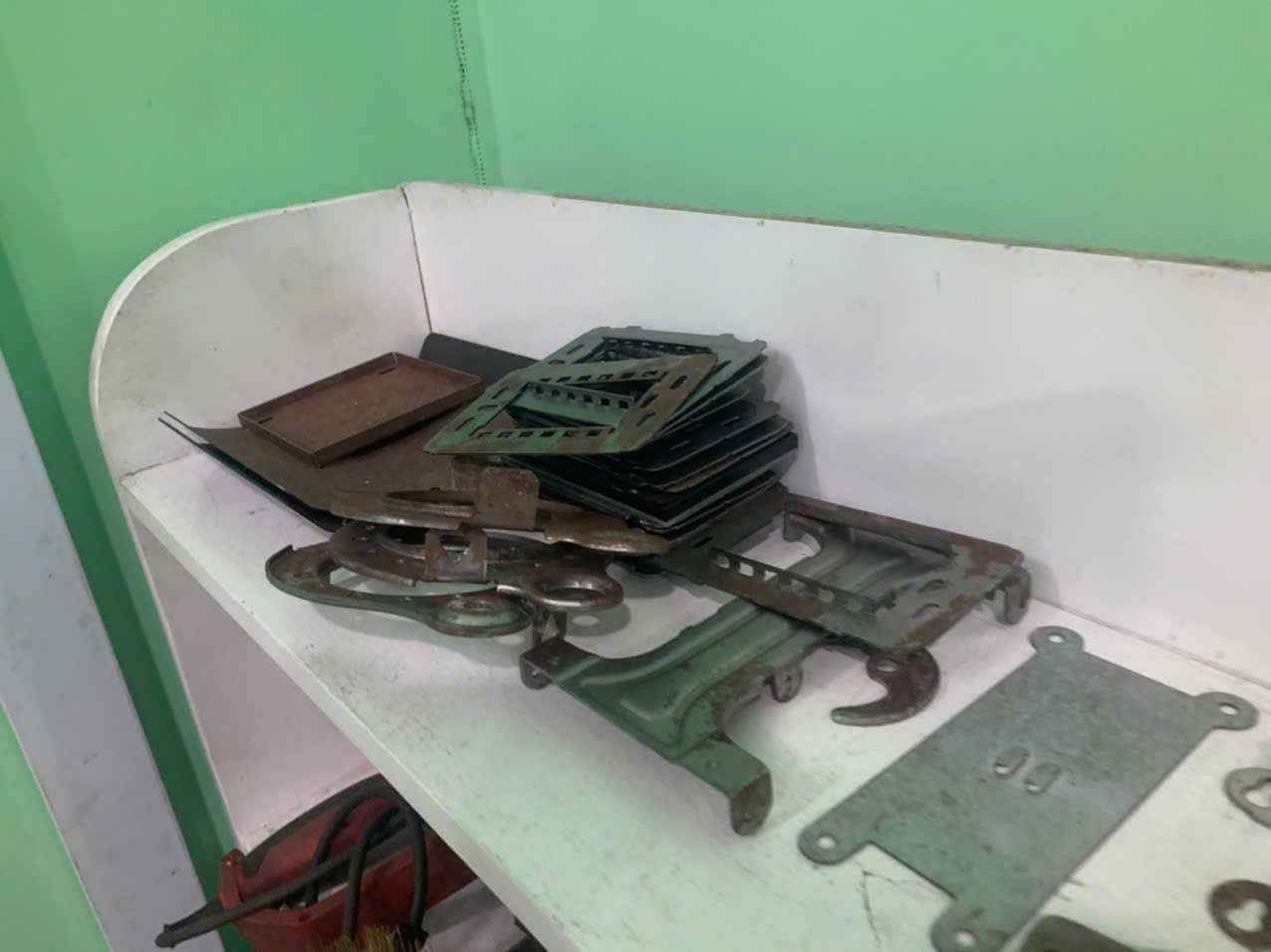
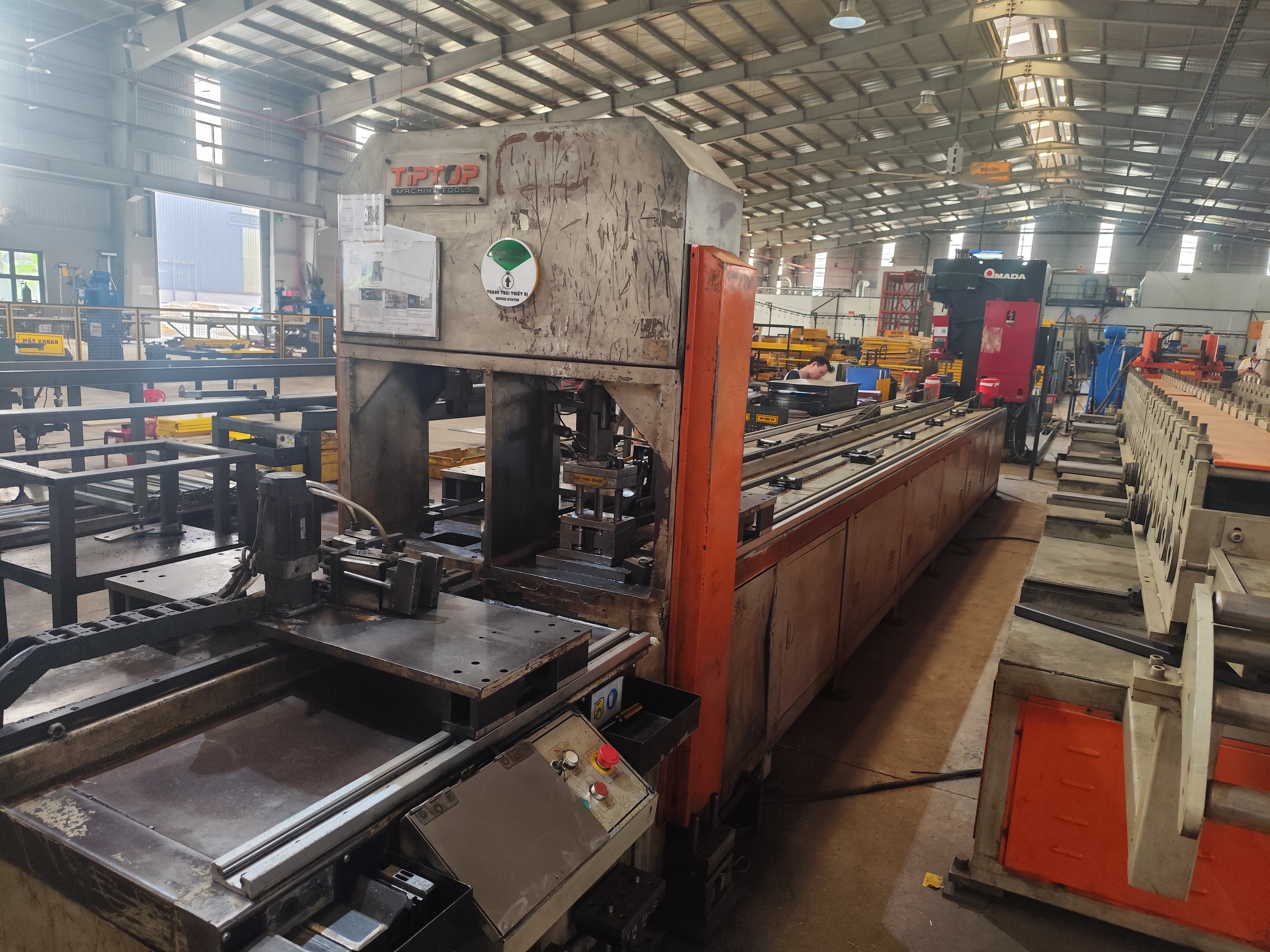
Knowing when stamping parts need scrapping and replacement saved one of our Vietnam production runs from a full customer rejection springback 1. A borderline part shipped is a warranty claim waiting to happen.
Stamping parts need scrapping and replacement when defects like cracks, out-of-tolerance dimensions, or excessive burrs cannot be reliably reworked to meet drawing requirements, when the defect affects fit, function, safety, or compliance, or when repair costs exceed roughly 60–70% of replacement cost.
That is the short answer. The full answer is a decision process. Below, I walk through wear limits, tolerance checks, early warning signs, and the repair-versus-replace math we use on real projects.
How can I tell if wear on my stamping parts has crossed the line into scrap territory?
A purchasing manager in the US once emailed me photos of brackets with fuzzy edges and asked one question: salvageable or scrap? Our QC team in Vietnam had the answer within a day.
Wear crosses into scrap territory when burr height exceeds the drawing specification, cutting edges show visible rounding or chipping, surface galling or dents affect mating faces, or cracks appear at bend radii. Cosmetic wear can often be sorted; functional or structural wear cannot.

The key distinction we teach every inspector on our lines is simple: cosmetic versus functional. A light scratch on a non-mating surface of a zinc-plated bracket may pass with a concession. A burr on a screw hole that will sit against a gasket will not. The defect location matters as much as the defect size.
The wear indicators we check first
Burrs are the earliest and most honest signal. When punch and die clearance is correct and edges are sharp, burr height stays low and consistent. As the cutting edge wears and rounds, burr height climbs. Once it exceeds the allowable limit on the drawing, the parts are non-conforming, and the tooling needs grinding before you make more of them.
Cracks and splits are different. They are almost never reworkable. A crack at a bend radius on a Z-fold clip means the material has already failed. Sorting those parts out is mandatory, and scrapping them is the only safe disposition.
| Wear Type | Typical Cause | Disposition Tendency |
|---|---|---|
| Burr height over spec | Dull cutting edge, wrong clearance | Rework possible if deburring is approved; fix tooling |
| Cracks or splits | Excess forming stress, tight radii, material mismatch | Scrap — not repairable |
| Galling, scoring | Contamination, poor lubrication, die pickup | Sort; scrap if mating surface affected |
| Dents, indentations | Debris in die, handling damage | Sort; scrap if fit-critical zone |
| Wrinkles | Low blankholder force, poor restraint | Usually scrap on formed flanges |
One more point from our supplier audits across Vietnam and China: the same visible defect can mean different things. A one-off dent from handling is a containment issue. Rising burrs across a whole shift is a tooling issue, and it means the suspect lot is much bigger than the visibly bad parts.
What dimensional tolerances should I check before deciding to replace a stamping die component?
During PPAP submissions 2 for our US clients, dimensional layout reports are where die wear hides in plain sight. Numbers drift long before parts visibly look wrong.
Check hole diameters and positions, bend angles, flange heights, hole-to-edge distances, flatness, and overall profile against the engineering drawing. Replace or regrind the die component when measurements approach the tolerance limit consistently, or when SPC charts show sustained dimensional drift toward a boundary.

Here is the mindset shift I push with every supplier we manage: do not wait for a part to fail. Watch the trend. A hole diameter that measures dead-center of tolerance on Monday and near the upper limit on Friday is telling you the punch is wearing. Statistical process control 3 charts make this visible. When the trend line points at the tolerance boundary, you schedule die maintenance before you build a pile of scrap.
The critical dimensions on a typical stamped bracket
Take a simple mounting bracket with two punched holes, one round and one slotted, plus several 90-degree bends. These are the checks we run at final inspection:
| Feature | What to Measure | Why It Drifts |
|---|---|---|
| Round hole diameter | Pin gauge or caliper | Punch wear enlarges or distorts holes |
| Slot width and length | Gauge pins, optical comparator | Punch edge rounding, feed misalignment |
| Hole position | Height gauge, CMM | Die misalignment, strip feed error coordinate measuring machine 4 |
| Bend angle | Angle gauge, protractor | Springback change from die wear or material variation |
| Flange height | Caliper, height gauge | Form station wear, setup error |
| Flatness | Surface plate and feeler gauge | Die pressure loss, material stress |
Reading the results
If one dimension is out on one part, suspect setup or handling. If the same dimension trends out across many parts, suspect the die. And remember grinding limits. Every punch and die section has a finite regrind allowance. Once the cumulative grinding reaches that limit, the component itself must be replaced, not sharpened again. We log regrind depth on every tool we manage so this never comes as a surprise mid-project.
Are there warning signs during production that signal my stamping parts are about to fail?
An operator on one of the lines we audit flagged a press that "sounded different" on the downstroke. He was right. The punch had chipped, and his ears caught it before the gauges did.
Yes. Warning signs include abnormal press noise, rising burr height, surface dullness or scratch marks on parts, slug pulling, inconsistent springback, changes in press force or vibration, and rough part backsides. These signal die wear or damage before parts fall fully out of specification.

Production lines talk to you constantly. The trick is knowing what to listen for. In my experience coordinating process control across our Vietnam and China operations, the earliest signals are almost always indirect. The parts still measure in spec. But something upstream has changed, and the clock has started.
Sensory signals worth acting on
Sound comes first. A sharp cutting edge makes a clean, consistent snap. A worn or chipped edge tears rather than shears, and the sound changes. Experienced operators catch this reliably.
Surface finish comes second. When stamped parts lose their bright sheen and turn dull, or when scratch marks appear on formed faces, the die surface is degrading or picking up material. Galling on the die transfers directly onto every part that follows.
Feel comes third. Inspectors running gloved fingers along edges catch growing burrs long before anyone measures them.
Instrumented signals
Modern lines add hard data on top of human senses. This is a real trend we see clients adopting:
- Press force monitors flag tonnage shifts that indicate edge wear or material variation.
- Vibration sensors 5 detect chipped punches through changed signatures.
- Temperature monitoring catches lubrication failure before galling starts.
- Machine vision systems 6 spot splits and surface defects at full line speed, with far more consistency than tired human eyes.
The shift here is from fixed-interval maintenance to condition-based maintenance 7. Instead of regrinding every set number of strokes, you regrind when the signals say the edge is going. That protects both the tooling budget and the parts. Either way, the rule is the same: when a warning sign appears, quarantine everything made since the last known-good check. Traceability turns a vague worry into a contained, inspectable lot.
How do I calculate the cost tradeoff between repairing and replacing worn stamping parts?
Payment terms taught me this lesson. When we offer open account terms to US clients, cash discipline runs both ways — so we scrutinize every repair-versus-replace decision on tooling as if the money were our own.
Compare total repair cost, including labor, downtime, and remaining tool life, against new component cost. If repair exceeds roughly 60–70% of replacement cost, replacement is generally more economical. Always add the hidden risk cost of repaired tooling failing again mid-production.
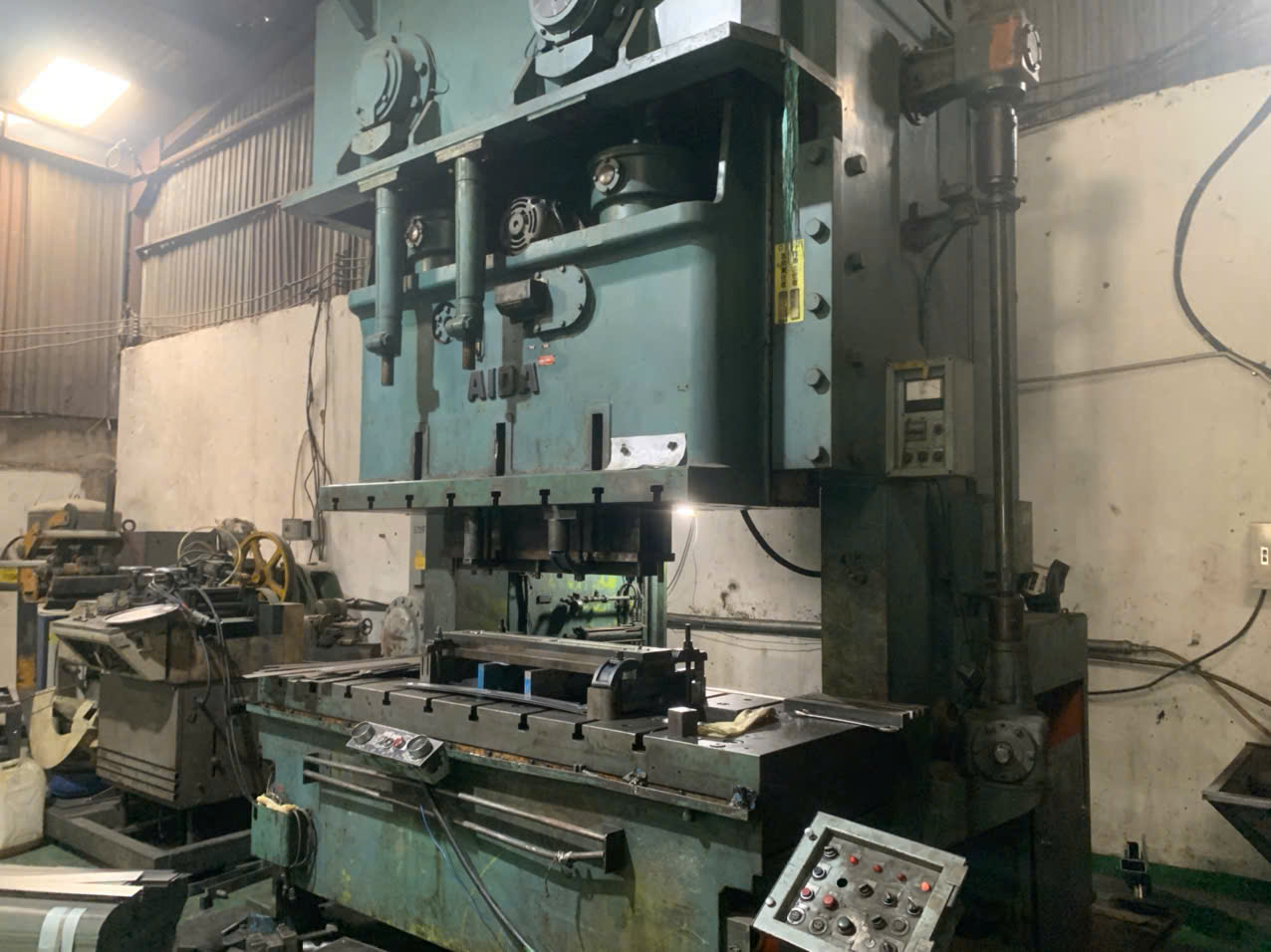
The naive math is easy: regrinding a punch costs a fraction of a new one, so repair wins. The real math is messier, and getting it wrong is expensive in both directions. Repair too long and you accumulate scrap, downtime, and quality escapes. Replace too early and you burn tooling budget for no benefit.
The full cost picture
Here is the framework we use when advising clients on contract manufacturing projects:
| Cost Factor | Repair Route | Replace Route |
|---|---|---|
| Direct cost | Grinding, welding, polishing labor | New component purchase price |
| Downtime | Often shorter, sometimes repeated | Longer once, then stable |
| Remaining life | Reduced with each regrind | Full rated stroke count |
| Failure risk | Rises as grinding limit nears | Low with a proven design |
| Quality risk | Repaired edges may drift faster | Consistent output |
| Scrap exposure | Higher if repair underperforms | Lower |
A simple decision sequence
First, check the regrind allowance. If the component is at or near its grinding limit, the decision is made for you: replace.
Second, price the repair honestly. Include teardown, the repair itself, reassembly, tryout, and first-article inspection. Include the production hours lost. A cheap regrind that costs two shifts of output is not cheap.
Third, apply the threshold. If the honest repair total lands above 60–70% of a new component, buy new. Below that, repair — but log it, because the third repair on the same section usually signals a design or material problem, not bad luck.
Fourth, weigh delivery risk. For a client with a firm ship date, a repaired tool that might fail mid-run can cost far more than the price difference. We have swapped in new die sections purely to protect an on-time delivery, and no client has ever complained about that choice. Late shipments destroy trust faster than any invoice line.
Conclusion
Scrapping stamping parts is not a judgment call — it is a documented decision built on wear limits, dimensional data, early warning signs, and honest cost math. Get it wrong and you ship risk; get it right and you protect quality, delivery, and trust.
Frequently Asked Questions
How can I tell if wear on my stamping parts has crossed the line into scrap territory?
A purchasing manager in the US once emailed me photos of brackets with fuzzy edges and asked one question: salvageable or scrap? Our QC team in Vietnam had the answer within a day.
What dimensional tolerances should I check before deciding to replace a stamping die component?
During PPAP submissions 2 for our US clients, dimensional layout reports are where die wear hides in plain sight. Numbers drift long before parts visibly look wrong.
Are there warning signs during production that signal my stamping parts are about to fail?
An operator on one of the lines we audit flagged a press that "sounded different" on the downstroke. He was right. The punch had chipped, and his ears caught it before the gauges did.
Footnotes
1. Technical metal forming concept referenced for bend angle variation in stamping. ↩︎
2. PPAP relates to ISO quality standards referenced in production part approval process. ↩︎
3. SPC charts are central to detecting dimensional drift discussed in the article. ↩︎
4. CMM is a standard measurement tool referenced for hole position inspection accuracy. ↩︎
5. Instrumented monitoring technology referenced for detecting tooling wear during production. ↩︎
6. Background concept on automated inspection technology mentioned for defect detection. ↩︎
7. Core maintenance strategy concept explained as alternative to fixed-interval regrinding. ↩︎