
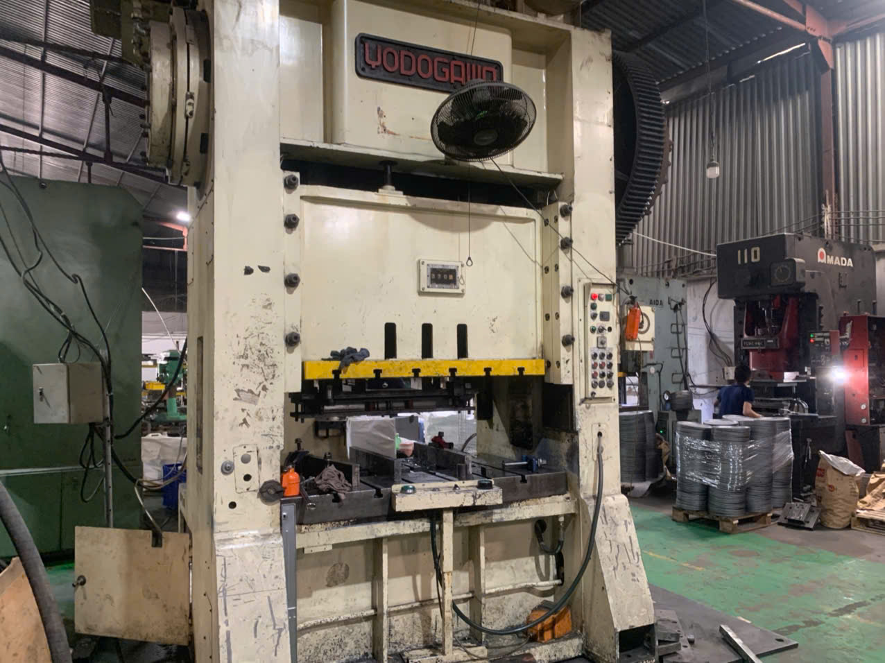
Stamping parts samples can look perfect and still fail in your assembly line. I have watched buyers approve shiny brackets by eye, then face costly rework. Our team learned to verify with evidence, not appearance.
Stamping parts samples meet quality standards when every dimension matches the drawing tolerances, material certificates confirm the specified grade and hardness, surfaces are free of burrs and defects, functional fit tests pass, and PPAP or FAI documentation proves the process is stable and repeatable.
That answer sounds simple. In practice, each element needs a clear method. Below, I walk you through the exact steps we use to judge stamped samples before releasing mass production.
How can I verify stamping parts samples against my engineering drawings and tolerances?
A few years back, a client sent us a drawing with a flatness callout buried in a corner note. The supplier missed it. We caught it during sample review, and that habit stuck with our team ever since.
Verify stamping parts samples by creating a ballooned drawing that numbers every dimension, measuring each feature against its tolerance zone, checking GD&T callouts like flatness and hole position, and recording actual values in a dimensional report signed by both supplier and buyer.
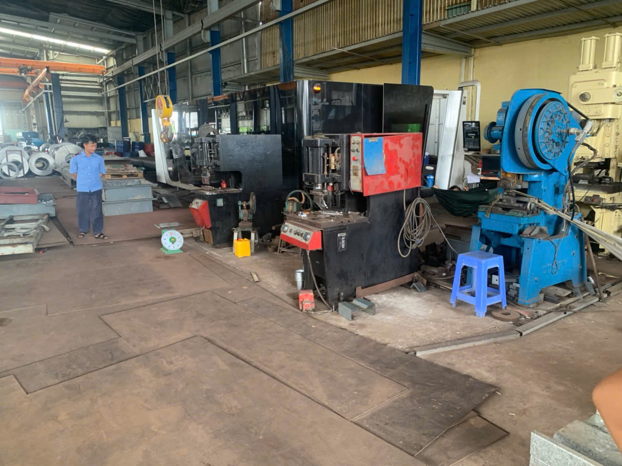
The drawing is the contract. If you do not verify the sample against every requirement on it, you are approving on trust, not evidence. Here is the process we follow on every custom stamping project we manage from our Vietnam and China offices.
Start with a ballooned drawing
First, number every dimension, note, and callout on the drawing. This is called ballooning. Each balloon gets a line in the inspection report. Nothing gets skipped. Small notes matter most. Burr direction, grain direction, coating thickness, and heat treatment often hide in text blocks, not in the dimension boxes.
Separate critical from general dimensions
Not all dimensions carry the same risk. We classify them before measuring.
| Dimension Type | Examples | How Strict? |
|---|---|---|
| Critical (CTQ) | Hole position, mating surfaces, bend angles | Must be in tolerance, often measured on multiple samples |
| Major | Overall length, flange height, slot width | Measured on every sample, in tolerance |
| Minor / Reference | Cosmetic radii, non-mating edges | Checked, but small deviations may be negotiable |
Check the tolerance stack, not just single features
A bracket can pass every individual dimension yet still fail assembly because tolerances stack across multiple bends. On stepped Z-profile clips like the ones we often source, we always check the cumulative height across all bends, not just each bend angle alone.
One more tip from experience: measure again after 24 to 48 hours. Springback and residual stress 1 can shift readings slightly after forming, especially on thin-gauge steel. A sample measured hot off the press may not match the same part two days later.
What inspection methods should I use to check dimensional accuracy of stamping samples?
There is always a trade-off we weigh on every project: measurement speed versus measurement depth. A caliper check takes seconds. A CMM report takes hours. Choosing the wrong tool wastes money or hides defects.
Use calipers, micrometers, and height gauges for basic features; a CMM or 2.5D vision system for hole positions and GD&T callouts; go/no-go gauges for fast repeat checks; and 3D optical scanning for complex formed surfaces compared against the CAD model.
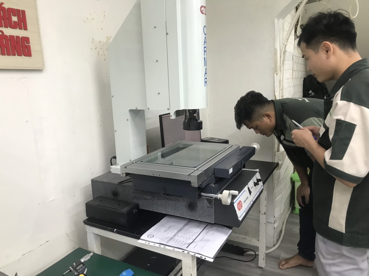
Match the tool to the feature and the risk. That is the core rule. Our inspectors in Vietnam keep a simple decision logic on the wall, and I will share the essence of it here.
Match the measurement tool to the feature
| Feature to Check | Recommended Method | Why |
|---|---|---|
| Length, width, thickness | Calipers, micrometers | Fast, accurate enough for ±0.1 mm class tolerances |
| Hole diameter | Pin gauges, plug gauges | More reliable than calipers on small holes |
| Hole position, true position | CMM or 2.5D vision system | Calipers cannot verify positional GD&T reliably |
| Flatness, parallelism | Surface plate with dial indicator, CMM | Captures form errors across the whole surface |
| Bend angles | Angle gauges, protractor, CMM | Springback makes angles a common failure point |
| Complex 3D formed shapes | 3D optical scanning vs CAD | Point-cloud comparison reveals subtle surface deviation |
Do not forget the measurement system itself
A measurement is only as good as the instrument and the person using it. Ask when the supplier last calibrated their tools. Ask whether they have done a gauge R&R study 2 on critical features. We have seen "out of tolerance" disputes that were really just two teams using different datum setups. Agree on datums and fixturing before anyone measures anything.
Measure more than one sample
One perfect part proves very little. For dimensional accuracy, we request at least five samples from a stable run, ideally taken from the start, middle, and end of the sample lot. Consistent readings across samples tell you the process is centered. Scattered readings, even if all pass, warn you the process is drifting near the tolerance edge.
How do I know if my supplier's PPAP documentation proves consistent quality control?
A U.S. purchasing manager once told me his previous supplier sent a "PPAP" that was one page of checkmarks. When we prepare PPAP packages 3 for our clients' stamping projects, we treat each element as evidence, not paperwork.
A credible PPAP includes a complete dimensional report tied to a ballooned drawing, material certificates matching the actual coil used, process flow diagram, PFMEA, control plan, capability studies showing Cpk of 1.33 or higher on critical dimensions, and measurement system analysis.

PPAP exists to answer one question: can this supplier make conforming parts repeatedly, not just once? Here is how to read the package critically instead of just filing it.
The elements that actually predict consistency
Some PPAP elements are formalities. Others are predictive. Focus your review time on these:
| PPAP Element | What It Proves | Red Flags to Watch |
|---|---|---|
| Dimensional results | The sample meets the drawing | Missing balloons, all values suspiciously "nominal" |
| Material certification | Correct grade, temper, thickness | Cert date or coil number does not match the sample lot |
| Process capability (Cpk/Ppk) | The process can hold tolerance over time | Cpk below 1.33 on critical dimensions, or no study at all |
| Control plan | Defects will be caught in production | Vague inspection frequency like "periodic" |
| PFMEA | Risks were analyzed before production | Generic template not specific to your part |
| MSA / Gauge R&R | Their measurements are trustworthy | No study on the gauges used for critical features |
Cross-check, do not just collect
The strongest verification is cross-referencing. Does the material cert heat number match the traceability label on the sample bag? Does the control plan mention the same critical dimensions flagged on the drawing? Does the capability study use real production tooling, not a prototype die? When we audit stamping suppliers across Vietnam and other Asian countries, mismatches between documents are the most common early warning sign of weak quality systems.
Ask about what happens after PPAP
Approval is a snapshot. Progressive dies wear. Coils change. Ask how the supplier monitors production: SPC charts on critical dimensions, first-pass yield tracking, and layered audits. A supplier who can show live SPC data from a current job is far more convincing than one with a beautiful but static PPAP binder.
What defects should I look for when evaluating first-article stamping samples before mass production?
Early in my sourcing career, I approved a batch of zinc-plated clips that looked flawless. Three months later, they showed white rust in a coastal warehouse. Since then, our checklist covers defects you can see and defects you cannot.
Inspect first-article stamping samples for burrs and sharp edges, cracks at bend radii, springback beyond angle tolerance, surface scratches, dents, rust, oil contamination, deformed or mispositioned holes, wrong material or thickness, and coating failures found through adhesion and salt spray testing.

Stamping defects fall into predictable families. If you know where each defect comes from, you also know how serious it is and whether it will get worse in mass production.
Defects by category and root cause
- Edge defects. Burrs, slivers, and rollover come from punch-die clearance 4 and tool wear. A burr on a first article is a warning: it will grow as the die wears. Check burr height with a micrometer, and confirm burr direction matches the drawing note.
- Forming defects. Cracks at bend lines, orange peel texture, wrinkling, and thinning point to wrong bend radius, wrong grain direction, or unsuitable material temper. Inspect bend radii under magnification, especially on high-strength steel.
- Dimensional defects. Springback pushes bend angles out of tolerance. Hole distortion happens when holes sit too close to a bend. Measure hole roundness near bends, not just hole diameter.
- Surface defects. Scratches, dents, die marks, rust, and oil stains. Judge them under agreed lighting, at an agreed distance, using approved boundary samples so accept/reject is not subjective.
- Material defects. Wrong alloy, wrong hardness, wrong thickness. The part can look perfect. Verify with the mill certificate and, for critical parts, an independent hardness or thickness check.
- Coating defects. Thin plating, poor adhesion, missed coverage inside holes. Visual checks are not enough. Request cross-hatch adhesion tests and salt spray results 5 when corrosion resistance matters.
Decide severity before you decide pass or fail
Not every defect kills a sample. A light die mark on a hidden surface may be acceptable. A burr on a mating edge is not. We classify each finding as critical, major, or minor against an agreed AQL scheme 6, then decide: pass, conditional pass with corrective action, or reject. Documenting that decision protects both sides when production starts.
Conclusion
A passing sample is not the goal. Proven, repeatable conformance is. Verify drawings, measure properly, audit PPAP evidence, and hunt defects systematically, and your stamping parts samples decision becomes low-risk.
Frequently Asked Questions
How can I verify stamping parts samples against my engineering drawings and tolerances?
A few years back, a client sent us a drawing with a flatness callout buried in a corner note. The supplier missed it. We caught it during sample review, and that habit stuck with our team ever since.
What inspection methods should I use to check dimensional accuracy of stamping samples?
There is always a trade-off we weigh on every project: measurement speed versus measurement depth. A caliper check takes seconds. A CMM report takes hours. Choosing the wrong tool wastes money or hides defects.
How do I know if my supplier's PPAP documentation proves consistent quality control?
A U.S. purchasing manager once told me his previous supplier sent a "PPAP" that was one page of checkmarks. When we prepare PPAP packages 3 for our clients' stamping projects, we treat each element as evidence, not paperwork.
Footnotes
1. NIST manufacturing resources cover residual stress effects on formed metal parts and dimensional stability. ↩︎
2. Background on gauge repeatability and reproducibility studies used to validate measurement reliability. ↩︎
3. Explains the PPAP framework manufacturers use to prove repeatable stamping process capability. ↩︎
4. ISO tolerance standards inform correct punch-die clearance settings that prevent burr formation. ↩︎
5. ASTM B117 is the standard salt spray corrosion test referenced for evaluating coating durability. ↩︎
6. Defines the acceptable quality limit sampling standard referenced for defect severity classification. ↩︎
7. ISO standard defines salt spray corrosion testing referenced for coating verification. ↩︎