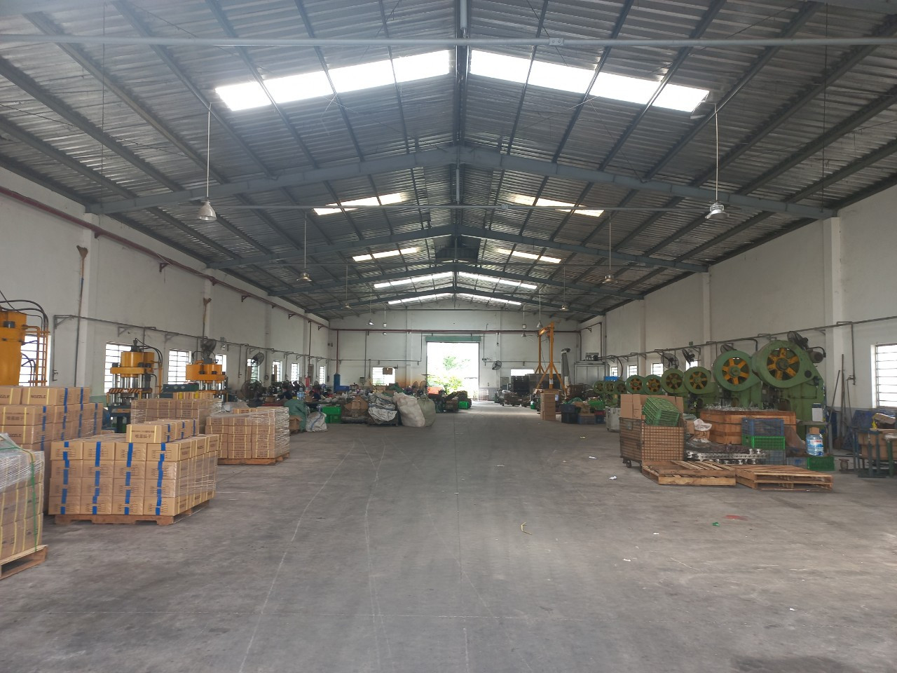

I once watched a $40,000 batch of custom mounting brackets fail at assembly because the tolerance callouts on the drawing didn’t match what the fabricator could actually hold — a costly lesson that changed how our team approaches every infrastructure sourcing project.
Sheet metal fabrication tolerances for infrastructure projects are best determined by starting with ISO 2768-m as a general baseline, then tightening only the critical features that affect fit and function. Early collaboration with your fabricator, empirical bend testing, and a clear tolerance hierarchy on your drawings prevent costly rework and assembly failures.
This article walks you through a practical framework ISO 2768 standard class M 1. We cover standard tolerances, cost and lead-time impacts, quality control validation, and how to communicate complex specs to an offshore manufacturer. Each section draws on real project experience from our work coordinating custom parts across Asian supply chains for U.S. buyers.
What standard sheet metal tolerances should I expect for my infrastructure project components?
A buyer we work with in the Midwest once sent us a drawing with no general tolerance block at all — just a note saying "hold tight." That single ambiguity triggered three rounds of sample revisions and delayed the project by six weeks Production Part Approval Process 2.
For most infrastructure sheet metal components, the ISO 2768 standard class M (medium) is the accepted default. It specifies ±0.3 mm for linear dimensions under 120 mm and ±1.0° for angular bends. Tighter tolerances like ±0.1 mm are achievable but should only be applied to critical mating features.
ISO 2768-m as Your Starting Point
The ISO 2768 standard exists precisely to eliminate ambiguity. It defines four tolerance classes — Fine (F), Medium (M), Coarse (C), and Very Coarse (V). For sheet metal work, class M is the most widely used because it balances precision fabrication processes with practical shop-floor capabilities. When our engineering team in Vietnam reviews incoming drawings, the first thing we check is whether the title block specifies a general tolerance standard. If it doesn't, we default to ISO 2768-m 3K and confirm with the client before cutting any material.
Linear, Angular, and Flatness Tolerance Ranges
Different feature types carry different tolerance expectations. Here is a quick reference:
| Tolerance Type | Typical Range (ISO 2768-m) | Tighter Custom Range |
|---|---|---|
| Linear dimensions (< 120 mm) | ±0.3 mm | ±0.1 mm |
| Linear dimensions (120–400 mm) | ±0.5 mm | ±0.2 mm |
| Angular dimension limits | ±1.0° | ±0.5° |
| Flatness requirements (per 300 mm) | ±0.5 mm | ±0.2 mm |
| Edge-to-edge distance | ±0.13 mm (±0.005 in) | ±0.08 mm |
| Bend-to-hole distance | ±0.25 mm (±0.010 in) | ±0.13 mm |
| Bend-to-bend distance | ±0.38 mm (±0.015 in) | ±0.20 mm |
These numbers are not universal. They shift depending on material type, material thickness variation in the raw stock, and the number of bending operations. A stated 16-gauge steel sheet (0.065 in) may actually measure 0.064 in, and that small difference compounds across multiple bends. For a deeper dive into what ranges are typical across different processes, see our guide on standard precision and tolerance ranges for sheet metal fabrication.
The "Loosest Acceptable First" Principle
Our approach is simple. Apply ISO 2768-m to the entire part first. Then review the assembly and identify only the features that truly affect form, fit, or function. Those get tighter callouts — often using Geometric Dimensioning and Tolerancing 4 (GD&T) symbols. Everything else stays at the general tolerance. This design for manufacturability 5 (DFM) philosophy keeps scrap rates low and avoids unnecessary cost escalation.
Why Bending Complicates Everything
Bending stretches material. The neutral axis shifts during the bend, and that shift changes the final dimension of adjacent features. The K-factor 6 — typically ranging from 0.3 to 0.5, with an average around 0.4468 — is the ratio used to calculate bend allowance and predict the flat pattern accurately. For infrastructure brackets with multiple bends, we strongly recommend producing 3 to 5 test pieces to empirically validate the K-factor before committing to a full production run. Sheet metal springback 7 is another variable; after the press brake releases, the material springs back slightly, and the actual angle may differ from the programmed angle by 0.5° to 2° depending on material and grain direction.
How will my tolerance requirements impact the total cost and lead time of my custom parts?
The trade-off between precision and price is something we negotiate on almost every infrastructure project. One recent order for custom enclosure panels came in with ±0.05 mm across every dimension — the kind of tolerance you'd see on a CNC-machined aerospace part, not a bent sheet metal bracket.
Tighter tolerances directly increase cost and lead time. Moving from ISO 2768-m (±0.3 mm) to custom tight tolerances (±0.1 mm) can raise fabrication costs by 25–50% and extend lead times due to slower processing, additional inspection, and higher scrap rates. Specify tight tolerances only where function demands it.
Where Cost Increases Come From
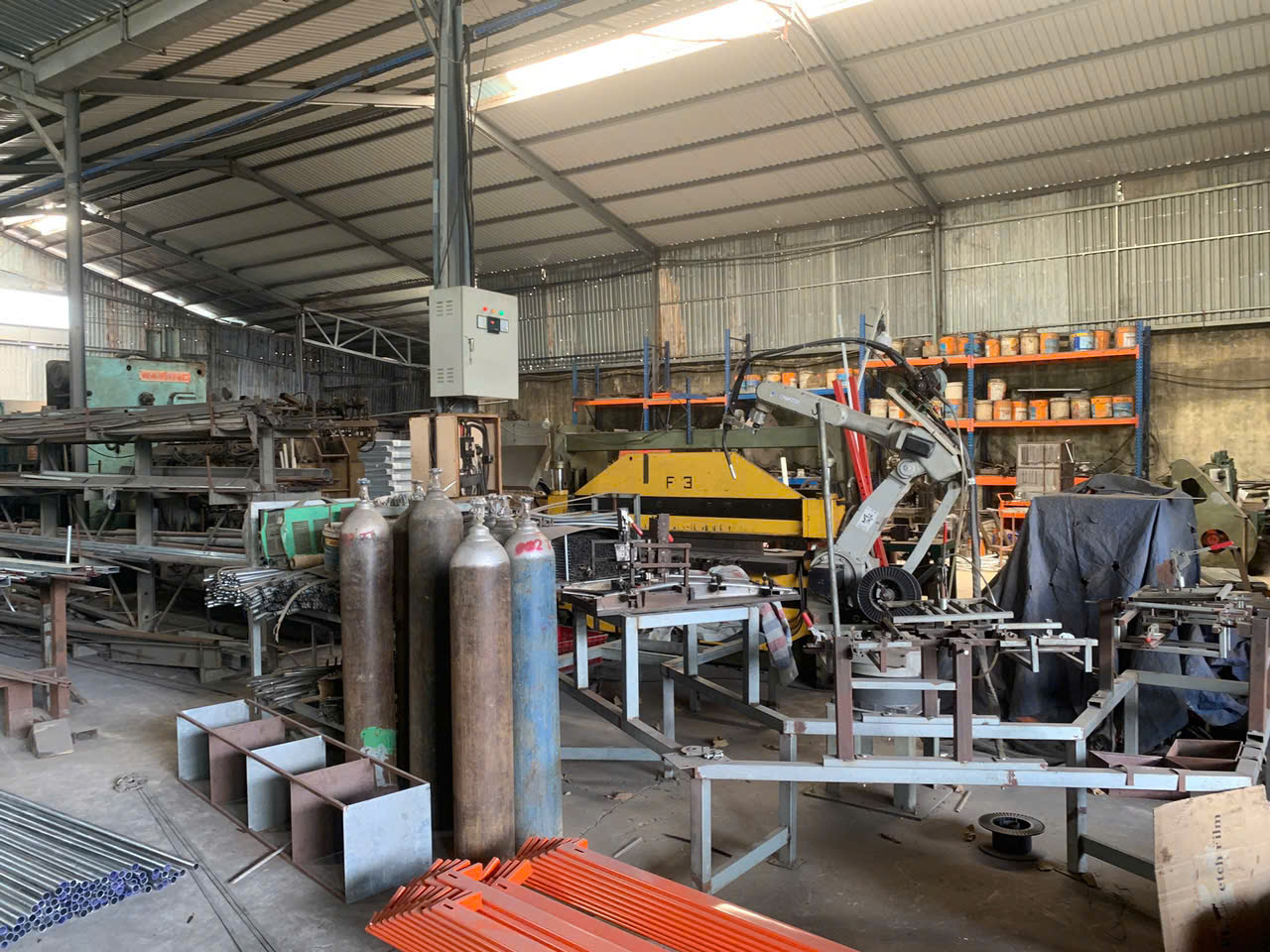
Tighter tolerances require slower machine feeds, more frequent tool calibration, and additional inspection steps. Each of these adds time and labor. In bending operations, achieving ±0.5° instead of ±1.0° often means switching from air bending to bottoming or coining — processes that use more tonnage, wear tooling faster, and require precise die setups. Our production partners in Vietnam and across Asia track these cost drivers carefully, and we pass that transparency on to our U.S. clients.
Sheet Metal vs. CNC Machining: A Cost Comparison
Many buyers come from machining backgrounds and expect similar tolerances from sheet metal. Here is a side-by-side comparison:
| Parameter | Sheet Metal Fabrication | CNC Machining |
|---|---|---|
| Typical linear tolerance | ±0.13–0.38 mm | ±0.025–0.05 mm |
| Typical angular tolerance | ±0.5°–1.0° | ±0.1°–0.25° |
| Cost per part (relative) | 1× | 3–8× |
| Lead time (prototype) | 5–10 days | 7–15 days |
| Best suited for | Brackets, enclosures, panels | Precision housings, shafts, fittings |
| Tolerance stack-up risk | Higher (multi-bend) | Lower (single-setup) |
The cost implications of tolerances are clear. If your infrastructure component can function within ±0.3 mm, insisting on ±0.05 mm is paying a premium for no added value.
How Tolerance Affects Yield and Scrap
When we run tolerance stack-up analysis on a multi-bend bracket, each additional tight callout reduces the statistical window for a "pass" part. A part with five bends, each held to ±0.5°, has a cumulative angular variation window of ±2.5° across the full geometry. If the final assembly can absorb that, there is no reason to tighten individual bends further. Tightening to ±0.25° per bend doesn't halve the risk — it roughly doubles the reject rate and adds a secondary inspection gate.
The Business Case for "Good Enough"
I often tell procurement teams: the goal is not the tightest tolerance — it is the right tolerance. If two mating flanges bolt together with M8 hardware through 9 mm clearance holes, holding the hole position to ±0.05 mm is overkill. The clearance already absorbs far more variation than that. Focus your tolerance budget on the features that have zero margin for error: datum surfaces, alignment pins, and press-fit interfaces.
How can I ensure my supplier has the right QC processes to meet my precision specifications?
Last year, we onboarded a new fabrication partner in Vietnam. Before placing a single production order, our local team spent two days on-site auditing their inspection equipment, operator training records, and corrective-action procedures. That upfront investment saved us from three potential quality escapes on a 2,000-piece bracket order.
Ensure your supplier uses documented quality control methods — including PPAP (Production Part Approval Process), first-article inspection with calibrated CMM equipment, in-process statistical checks, and final dimensional reports. Request sample validation before full production and verify that the shop's measurement capability matches your tightest tolerance callouts.

What to Audit Before You Commit
Not every fabricator who quotes your job can actually hold your tolerances. The gap between "we can do it" and "we have the process controls to do it consistently" is where most sourcing failures happen. When our team conducts supplier audits, we look at specific capabilities:
- Measurement equipment: Do they have a CMM (Coordinate Measuring Machine) 8, optical comparators, and calibrated gauges appropriate for the tolerance range? A shop quoting ±0.1 mm but measuring with a tape measure is a red flag.
- First-article inspection (FAI): Do they produce and fully inspect the first piece off the line before running the batch? Our standard protocol requires dimensional reports on the first 3–5 pieces.
- In-process checks: Are operators checking critical dimensions at regular intervals, or only at the end?
- Traceability: Can they trace each part back to the raw material lot, the machine, and the operator? For infrastructure components where structural integrity matters, material traceability is non-negotiable.
PPAP and Process Control
For U.S. buyers accustomed to automotive-grade discipline, we implement a PPAP framework on custom sheet metal projects. This includes control plans, process flow diagrams, measurement system analysis 9 (MSA), and capability studies (Cpk). These tools quantify whether the process can consistently hit the target — not just once, but every time.
Tolerance Validation Protocol
For high-stakes infrastructure projects, we recommend a structured validation sequence:
- Design review: Confirm all tolerance callouts are intentional and achievable.
- Test pieces: Fabricate 3–5 samples and fully inspect them.
- Empirical K-factor measurement: Compare actual bend dimensions to predicted values and adjust the flat pattern.
- Pilot batch: Run 20–50 pieces under production conditions and calculate process capability.
- Full production: Release the order with approved control plans and inspection frequencies.
This protocol catches problems early. It also builds a data record that supports continuous improvement on repeat orders.
Smart Sensors and Real-Time Feedback
Some of the more advanced shops we work with have integrated smart sensors into their press brakes. These systems measure the actual bend angle in real time and adjust the ram depth on the fly to compensate for material thickness variation and springback. This kind of closed-loop control is especially valuable for parts where angular dimension limits are critical and batch consistency must be maintained across thousands of pieces.
What are the best ways for me to communicate complex tolerance requirements to an offshore manufacturer?
Early in our business, a client emailed a PDF drawing with tolerances buried in a footnote on page three. The fabricator missed them entirely, produced 500 parts to general tolerance, and the whole batch was rejected at incoming inspection. That experience taught us that clarity in communication is not optional — it is the first quality control step.
Communicate tolerance requirements through clearly annotated CAD drawings with an explicit title block (e.g., "General Tolerances per ISO 2768-mK"), GD&T symbols on critical features, a written specification sheet listing all special requirements, and a kick-off call with your fabricator's engineering team to review every callout before production begins.
Title Block Clarity Is Non-Negotiable
The title block on your drawing is the first thing a fabricator reads. It must state the general tolerance standard clearly — for example, "General Tolerances according to ISO 2768-m." If it is missing or ambiguous, every dimension on the drawing becomes open to interpretation. Our engineering team flags missing title blocks immediately and requests clarification before quoting. This one practice alone eliminates a significant share of tolerance-related disputes. For more on preventing such issues, see our article on what technical specifications you should specify to avoid sheet metal fabrication disputes.
When to Use GD&T
Geometric Dimensioning and Tolerancing is powerful, but it should be used selectively. Apply GD&T symbols to features where basic ± tolerances cannot capture the full geometric requirement — such as flatness requirements on a datum surface, true position of a bolt-hole pattern, or perpendicularity of a flange to a base. Over-specifying GD&T on every feature clutters the drawing and increases inspection cost.
A Communication Checklist for Offshore Sourcing
Here is a practical checklist we use internally when transmitting drawings to our fabrication partners:
| Step | Action | Purpose |
|---|---|---|
| 1 | Confirm title block states general tolerance standard | Eliminate ambiguity on non-critical dimensions |
| 2 | Highlight critical dimensions in color or with flags | Direct fabricator attention to must-hold features |
| 3 | Provide a tolerance summary table (separate document) | Give a quick-reference list outside the drawing |
| 4 | Include material specification with thickness tolerance | Prevent material thickness variation surprises |
| 5 | Specify surface finish and coating requirements | Avoid post-process dimensional changes |
| 6 | Schedule a pre-production engineering review call | Confirm understanding before cutting metal |
| 7 | Request a DFM feedback report from the fabricator | Leverage their equipment knowledge for optimization |
| 8 | Define inspection method for each critical feature | Ensure measurement aligns with tolerance intent |
| 9 | Agree on sample quantity and approval criteria | Set expectations for first-article inspection |
| 10 | Establish a change-control process | Prevent undocumented revisions mid-production |
Leveraging DFM for Better Outcomes
Design for manufacturability feedback is one of the most underused tools in offshore sourcing. When we receive a drawing, our team reviews it against the specific equipment and tooling available at the production facility. We often suggest adjustments — such as increasing a bend radius to reduce springback, or shifting a hole location further from a bend line to avoid distortion. These small changes can relax a ±0.13 mm tolerance to ±0.25 mm without any impact on the assembly, saving cost and improving yield.
Digital Twin and Simulation
For large infrastructure assemblies, predictive simulation tools allow us to model tolerance stack-up analysis before any metal is cut. By running a virtual assembly with worst-case tolerance conditions, we can identify interference risks and adjust the design proactively. This is particularly important for components exposed to significant temperature fluctuations, where thermal expansion can introduce dimensional changes that exceed the original fabrication tolerances.
The Single-Contractor Advantage
One trend we see gaining traction is the move toward single-contractor projects. When multiple vendors fabricate different parts of the same assembly, each vendor interprets tolerances slightly differently. Small inconsistencies compound at assembly. By consolidating fabrication with one qualified supplier — and managing that relationship through a sourcing partner like our team — you maintain consistent tolerance control across every component. Learning how to communicate OEM tolerance requirements to sheet metal fabrication suppliers effectively is critical to making this approach work.
Conclusion
Getting sheet metal fabrication tolerances right starts with applying ISO 2768-m as your baseline, tightening only critical features, and collaborating early with your fabricator. Audit quality control methods, communicate clearly through annotated drawings, and validate with test pieces before committing to full production.
Frequently Asked Questions
What standard sheet metal tolerances should I expect for my infrastructure project components?
A buyer we work with in the Midwest once sent us a drawing with no general tolerance block at all — just a note saying "hold tight." That single ambiguity triggered three rounds of sample revisions and delayed the project by six weeks Production Part Approval Process 2 .
How will my tolerance requirements impact the total cost and lead time of my custom parts?
The trade-off between precision and price is something we negotiate on almost every infrastructure project. One recent order for custom enclosure panels came in with ±0.05 mm across every dimension — the kind of tolerance you'd see on a CNC-machined aerospace part, not a bent sheet metal bracket.
How can I ensure my supplier has the right QC processes to meet my precision specifications?
Last year, we onboarded a new fabrication partner in Vietnam. Before placing a single production order, our local team spent two days on-site auditing their inspection equipment, operator training records, and corrective-action procedures. That upfront investment saved us from three potential quality escapes on a 2,000-piece bracket order.
Footnotes
1. Details the ISO 2768 standard, including its various tolerance classes. ↩︎
2. Replaced with an authoritative source for quality processes. ↩︎
3. Explains the ISO 2768 standard and its application in manufacturing. ↩︎
4. Replaced with an authoritative Wikipedia article on the topic. ↩︎
5. Replaced with an authoritative Wikipedia article on the topic. ↩︎
6. Describes the K-factor as a critical ratio for calculating bend allowance in sheet metal. ↩︎
7. Explains springback as elastic recovery in sheet metal after bending. ↩︎
8. Replaced with an authoritative Wikipedia article on the topic. ↩︎
9. Explains MSA as a study to evaluate measurement system variability and reliability. ↩︎