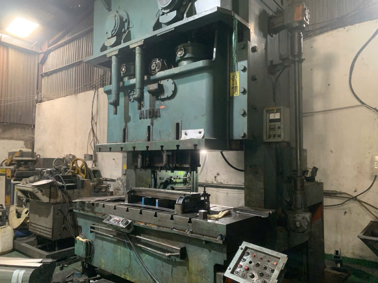

Ra surface roughness 1 for stamped parts confuses many buyers I work with. Specify too tight, and our quoting team flags the cost. Specify nothing, and quality disputes follow later.
Typical Ra surface roughness for stamped parts ranges from 0.4 to 6.3 µm, depending on process, tooling, and material. Most general stamped faces fall between 0.8 and 3.2 µm, and Ra 1.6 µm is a practical default unless sealing, contact, or cosmetic needs demand tighter values.
That range is wide for a reason. Let me walk you through what drives it, how to pick your number, and how to hold your supplier to it.
What Surface Roughness Range Can I Expect from Standard Stamping Processes?
During a recent bracket project we ran through our Vietnam supply base, the client's drawing simply said "smooth finish." Our engineers had to translate that into a measurable Ra band before the die maker could quote.
Standard stamping processes typically produce Ra 0.8 to 3.2 µm on formed faces. Precision stamping with fresh tooling can reach Ra 0.1 to 0.8 µm, while blanked or sheared edges often run rougher, from Ra 1.6 to 6.3 µm, depending on clearance and tool wear.
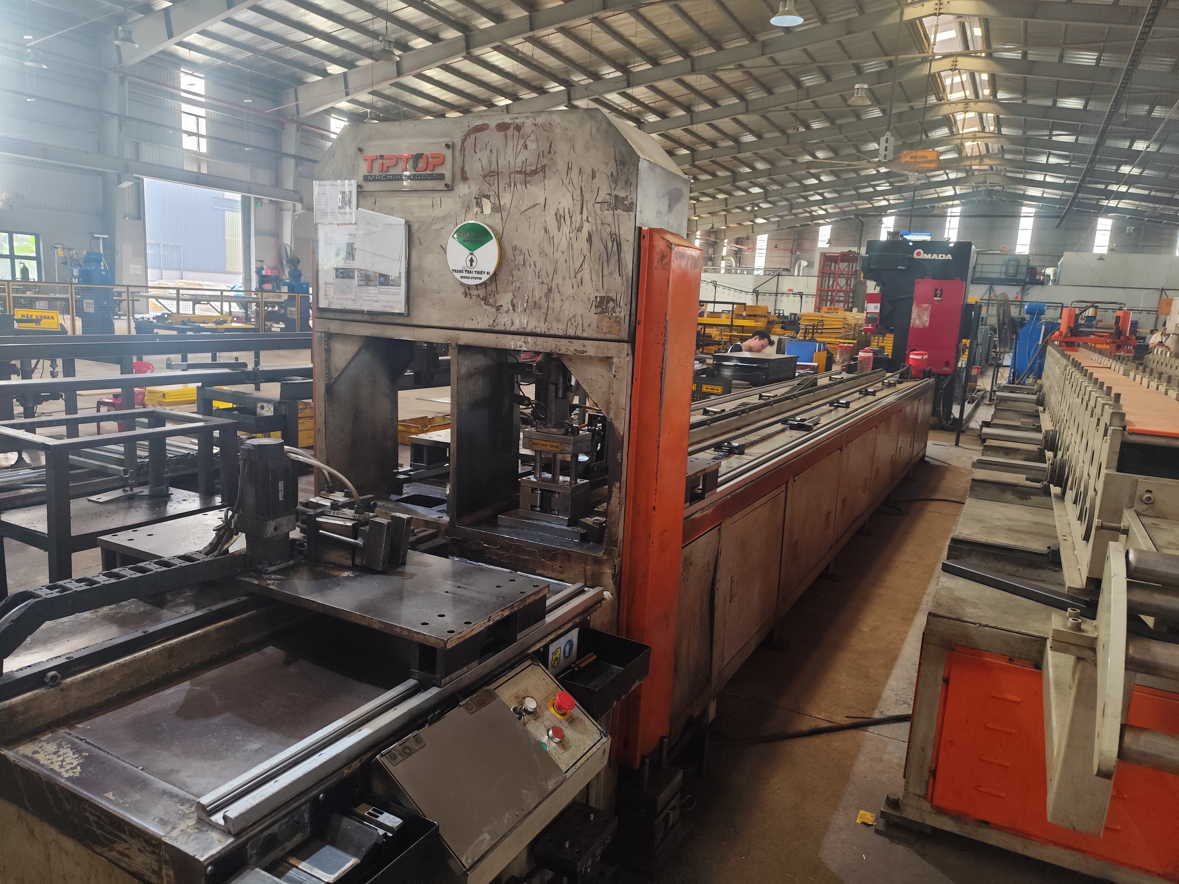
The first thing to understand is that "stamped part" describes several different surfaces at once. A single bracket, like the Z-shaped clips we source for hardware clients, has broad formed faces, bent radii, and sheared edges 2. Each surface tells a different roughness story.
Formed Faces vs. Cut Edges
The flat face of a stamped part mostly replicates the incoming coil surface. Stamping rarely improves it. So if your raw material arrives at Ra 0.5 µm, your stamped face will sit near that value or slightly above it. Cut edges are different. Shearing tears the material through fracture zones, so the edge roughness can be several times higher than the face.
Here is how the published ranges break down by category:
| Surface Category | Typical Ra Range | Notes |
|---|---|---|
| Precision stamped faces | 0.1–0.8 µm | Optimized tooling, fine coil stock |
| General stamped faces | 0.4–1.6 µm | Common sheet-metal work |
| Standard stamping/blanking | 1.6–6.3 µm | Includes edge conditions |
| Sheared/blanked edges | 1.6–6.3 µm+ | Fracture zone dominates |
| Post-polished stampings | Below 0.4 µm | Requires secondary operations |
Why the Published Numbers Conflict
You will find charts listing stamping at 0.4–1.6 µm and others listing 1.6–6.3 µm. Neither is wrong. The tighter figures describe high-quality faces under controlled conditions. The broader figures include blanking and general edge conditions. When we review drawings for clients, we always ask which surface the callout applies to. That single question prevents most disputes.
How Do I Choose the Right Ra Value for My Stamped Part's Application?
A purchasing manager in the U.S. once asked us to tighten every surface on a mounting clip to Ra 0.4 µm. When our project team asked what the part actually did, the answer was "it holds a panel behind a wall." We saved him roughly a third of the tooling cost by matching the spec to the function.
Choose Ra by function, not by habit. Use Ra 1.6 µm as a default for general stamped parts, tighten to 0.8 µm or below for sealing, sliding, or visible cosmetic surfaces, and allow 1.6–6.3 µm for hidden structural parts where finish does not affect performance.

Over-specifying is the most expensive mistake I see on stamped part drawings. Every step tighter than the process naturally delivers means better coil stock, more frequent die maintenance, or a secondary finishing operation. Each one adds cost and lead time.
Match Ra to What the Surface Does
Start with a simple question: what touches this surface? Here is the framework our engineers use during co-development reviews:
| Surface Function | Recommended Ra Target | Reasoning |
|---|---|---|
| Cosmetic / visible | 0.4–0.8 µm | Scratches and texture show under light |
| Sealing (gasket contact) | 0.8–1.6 µm | Too rough leaks; too smooth may not grip sealant |
| Sliding or contact | 0.4–0.8 µm | Reduces friction and wear |
| Electrical contact | 0.8 µm or finer | Ensures consistent contact resistance |
| Painted or coated later | 1.6–3.2 µm | Some roughness aids adhesion |
| Hidden structural | 1.6–6.3 µm | Finish adds no functional value |
When Ra Alone Is Not Enough
Ra is an average, so it hides extremes. Two surfaces can share the same Ra but behave very differently. For sealing surfaces and fatigue-critical parts, we recommend adding Rz to the drawing. Rz captures peak-to-valley height, which matters when a single deep scratch can start a leak or a crack. For most brackets, clips, and general hardware, though, Ra on its own is sufficient and keeps inspection simple.
One more practical tip: specify Ra only on the surfaces that need it. A drawing note reading "Ra 1.6 µm all over" forces the stamper to control edges that may never matter.
Which Factors in My Stamping Process Affect the Final Surface Roughness?
Tool wear taught me this lesson the hard way. Early in one high-volume clip program, first-article parts measured beautifully. Six months in, the client reported rougher edges. The die had worn, clearance had grown, and nobody had scheduled regrinding. We now build die maintenance intervals into every process control plan.
Final surface roughness on stamped parts depends on punch-die clearance, tool wear, incoming coil finish, material hardness and thickness, stamping speed, and lubrication. The mill-supplied coil surface usually sets the best achievable Ra, since stamping replicates rather than improves it.
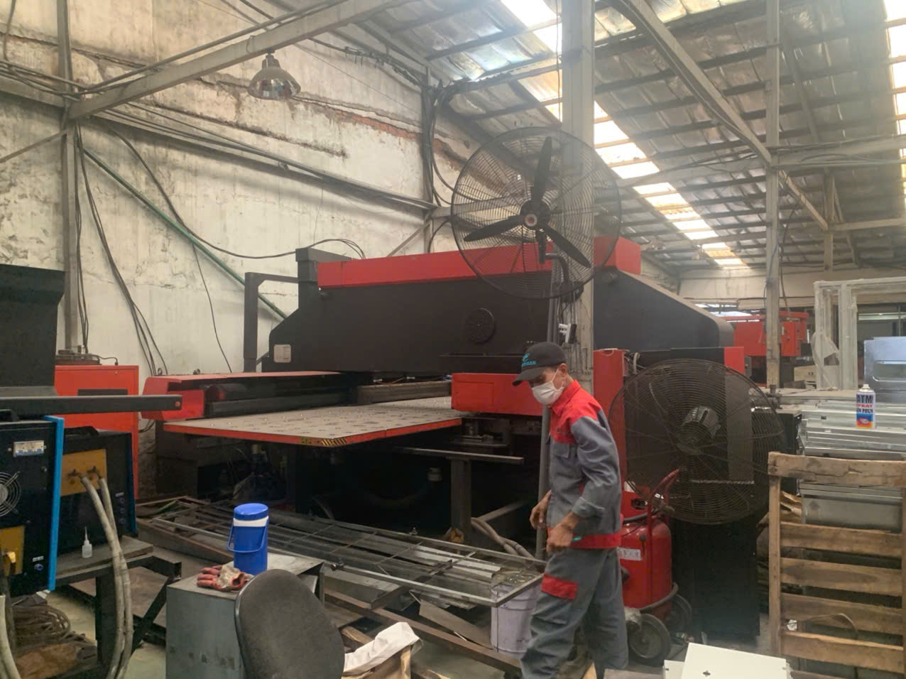
Think of stamping roughness as an inheritance plus a tax. The part inherits the coil's surface. Then the process adds a "tax" through tooling contact, shearing, and handling. Your job is to control both sides.
The Big Six Variables
| Factor | Effect on Ra | What Good Control Looks Like |
|---|---|---|
| Coil surface finish | Sets the floor for face Ra | Specify mill finish (e.g., 2B, BA) on the PO |
| Punch-die clearance | Tighter clearance widens the burnished band 3 and lowers edge Ra | Typically 5–10% of thickness, tuned per material |
| Tool wear | Ra drifts upward over die life | Scheduled regrinding and wear tracking |
| Material hardness | Harder alloys resist tearing but wear tools faster | Match die steel and coatings to the alloy |
| Stamping speed | High speed can raise heat and galling risk | Balanced speed with proper lubrication |
| Lubrication | Poor lube causes scoring and pickup | Consistent film, correct lube type |
Two Nuances Buyers Often Miss
First, rolling direction 4 matters. The coil's grain creates anisotropic roughness. Ra measured parallel to the rolling direction 5 can differ from the perpendicular reading by 20–40%. If your drawing does not state measurement direction, two honest labs can report different numbers on the same part.
Second, tighter clearance is not free. Reducing clearance increases the burnished band and locally lowers edge Ra, but it also raises burr risk and accelerates punch wear. Our process engineers treat clearance as a trade-off, not a dial you simply turn down.
How Do I Verify and Specify Ra Requirements When Working with a Stamping Supplier?
Reviewing supplier PPAP packages is a weekly routine for our China and Vietnam teams. The most common gap we find is a roughness callout on the drawing with no matching measurement record in the dimensional report. If nobody measures it, nobody controls it.
Specify Ra on the drawing per ISO 1302 or ASME Y14.36, naming the surface, the value, the measurement direction, and the standard (ISO 4287 or ASME B46.1). Verify with a calibrated stylus profilometer or optical tester, and require Ra data in PPAP and final inspection reports.

A roughness spec is only as strong as the paperwork behind it. Here is the process we follow with every new stamping supplier we audit, and it works whether you manage the supplier yourself or through a sourcing partner like us.
A Five-Step Verification Workflow
- Put it on the drawing correctly. Use the standard surface texture symbol. State the Ra value, the applicable surface, and the reference standard. Add measurement direction if grain matters.
- Confirm capability before tooling. Ask the supplier for Ra data from similar parts and the mill certificate finish of the proposed coil. If the coil cannot deliver your Ra, no die will fix it.
- Baseline at first article. Measure Ra during PPAP or first-article inspection with a calibrated contact profilometer. Record the values with locations marked on a ballooned drawing.
- Monitor over die life. Because Ra drifts upward as tooling wears, agree on a sampling frequency and an upper action limit. We suggest specifying an allowable range, not a single fixed number.
- Verify at final inspection. Include Ra checks in the outgoing inspection plan for critical surfaces, and keep the data traceable by lot.
Contact vs. Non-Contact Measurement
Stylus profilometers 6 are the workhorse. They are affordable, traceable, and accepted everywhere. Non-contact optical testers are faster and avoid scratching soft or plated surfaces, which helps on delicate precision stampings. For most brackets and clips, a stylus reading against ASME B46.1 or ISO 4287 settles any dispute quickly.
One final habit worth copying: write the acceptance range into the purchase agreement, not just the drawing. When commercial documents and technical documents agree, quality conversations stay short.
Conclusion
There is no single Ra for stamped parts. Match the value to function, control the process variables, and verify with data. Get the spec right, and disputes disappear.
Frequently Asked Questions
What Surface Roughness Range Can I Expect from Standard Stamping Processes?
During a recent bracket project we ran through our Vietnam supply base, the client's drawing simply said "smooth finish." Our engineers had to translate that into a measurable Ra band before the die maker could quote.
How Do I Choose the Right Ra Value for My Stamped Part's Application?
A purchasing manager in the U.S. once asked us to tighten every surface on a mounting clip to Ra 0.4 µm. When our project team asked what the part actually did, the answer was "it holds a panel behind a wall." We saved him roughly a third of the tooling cost by matching the spec to the function.
Which Factors in My Stamping Process Affect the Final Surface Roughness?
Tool wear taught me this lesson the hard way. Early in one high-volume clip program, first-article parts measured beautifully. Six months in, the client reported rougher edges. The die had worn, clearance had grown, and nobody had scheduled regrinding. We now build die maintenance intervals into every process control plan.
Footnotes
1. Explains the Ra parameter and how surface