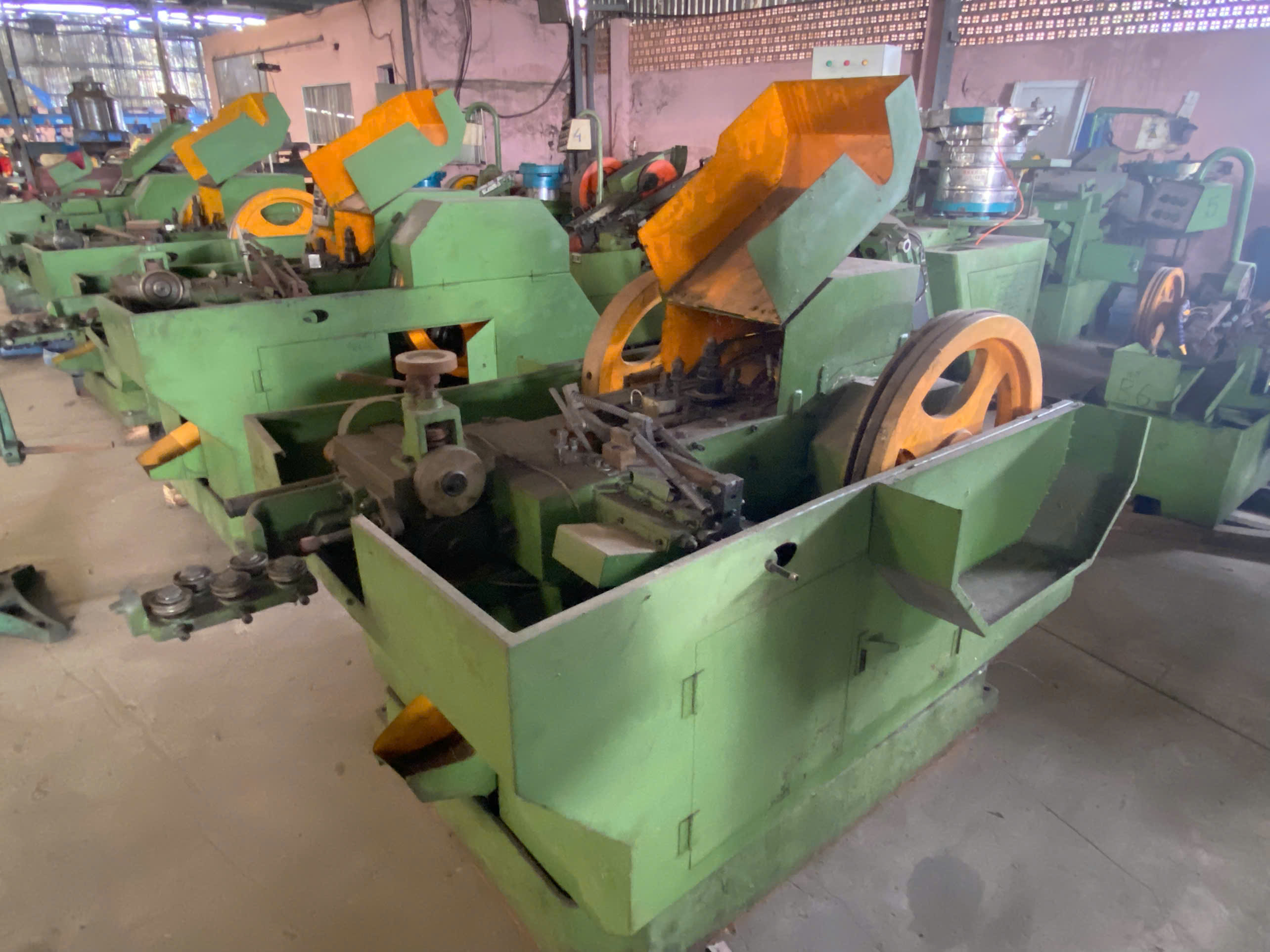

Last quarter, a batch of mounting brackets arrived at our warehouse with thickness deviations that went unnoticed — until they jammed our client’s assembly line and triggered a costly production halt.
To develop IQC inspection standards for incoming sheet metal parts, define critical dimensional tolerances from engineering drawings, establish surface finish acceptance criteria, implement AQL-based sampling plans, verify material certification documents, and create clear non-conformance handling procedures that align with your supplier’s quality control plan.
That experience reinforced what our quality team already knew: a solid incoming quality control process 1 is not optional. It is the first checkpoint that separates reliable production from expensive rework. Below, we walk through the exact framework we use — and refine daily — to inspect custom sheet metal parts before they ever reach a production floor.
What critical dimensions should I include in my sheet metal IQC checklist?
When we receive a new set of engineering drawings 2 from a U.S. client, the first thing our quality engineers do is highlight every dimension that directly affects fit, function, or assembly — because missing even one critical callout can cascade into a rejected shipment.
Your sheet metal IQC checklist should include material thickness, hole positions and diameters, bend angles, overall length and width, hole-to-edge distances, and flatness — prioritized by their impact on fit and function per the engineering drawings.
Start With the Drawing — Not Assumptions
Every inspection standard begins with the drawing. We pull every geometric dimension, tolerance, and note from the latest revision. Revision control matters enormously. If the supplier ships parts to Rev B while you inspect against Rev C, you will reject good parts or accept bad ones. We always confirm the revision number on the purchase order matches the drawing revision before any measurement begins.
The Six Dimensions That Matter Most
Not every dimension carries equal weight. Here is how we prioritize:
| Priority | Dimension Type | Why It Matters | Typical Tolerance |
|---|---|---|---|
| 1 | Material Thickness | Affects strength and assembly fit | ±0.03 mm (high-precision) |
| 2 | Hole Position & Diameter | Determines mounting accuracy | ±0.05 mm to ±0.10 mm |
| 3 | Bend Angle | Controls part geometry | ±0.5° to ±1° |
| 4 | Overall Length & Width | Ensures envelope fit | ±0.10 mm to ±0.25 mm |
| 5 | Hole-to-Edge Distance | Prevents cracking at edges | ±0.10 mm |
| 6 | Flatness / Surface Planarity | Affects mating surface contact | 0.10 mm per 100 mm |
For the gunmetal grey mounting brackets we frequently handle — parts with multiple pre-drilled holes and sharp bends — hole position relative to bend lines is the single biggest source of rejects. A 0.2 mm drift in hole location after bending can make the part unusable.
Measurement Tools Selection
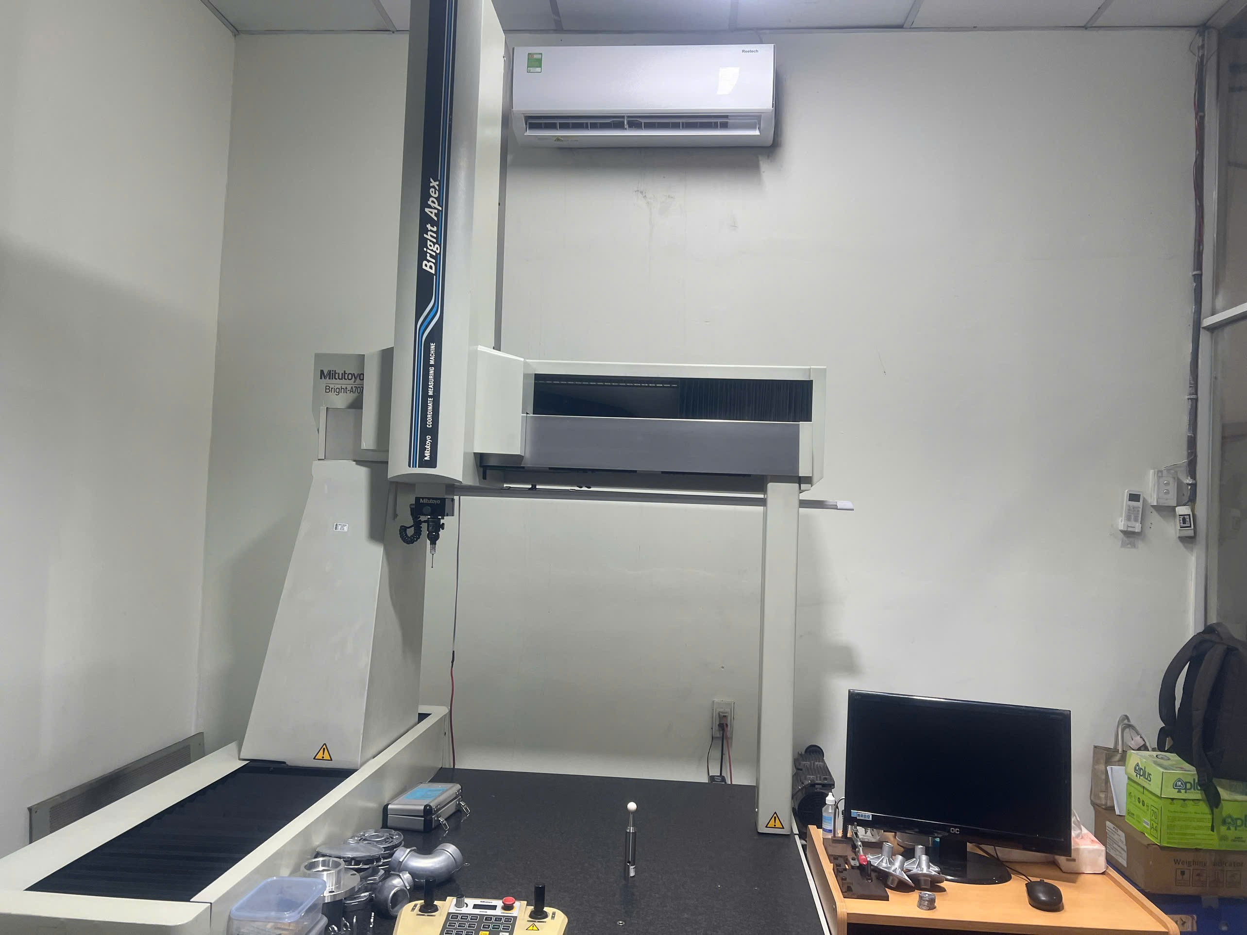
We match the tool to the tolerance. Calipers work for overall dimensions above ±0.10 mm. Micrometers handle thickness checks down to ±0.01 mm. For complex angular parts, we use a coordinate measuring machine (CMM) 3 during First Article Inspection. Pin gauges verify hole diameters faster than calipers on a production lot. Height gauges check flatness on a surface plate.
First Article Inspection Sets the Baseline
Before any production lot ships, we require a full First Article Inspection report 4 from the supplier. This FAI covers every single dimension on the drawing — not just the critical ones. It becomes the reference document. If a dimension passes FAI but drifts during production, we catch it through our ongoing lot sampling. This layered approach — FAI plus lot inspection — gives us confidence without inspecting every single part. For more detail on structuring your FAI procedures and standards for sheet metal fabrication, we have a dedicated guide.
How do I define acceptable surface finish and cosmetic standards for my custom parts?
A buyer once told us: "The parts measured perfectly, but they looked terrible — scratches everywhere." That conversation taught us that surface finish inspection needs the same rigor as dimensional checks, especially for visible or coated components.
Define acceptable surface finish by specifying roughness values (Ra), listing allowable and unallowable defect types, establishing inspection zones (critical vs. non-critical surfaces), and creating visual reference samples or limit samples that your supplier and inspectors can compare against.
Why Cosmetic Standards Are Hard to Enforce
Surface finish is subjective unless you make it objective. Words like "no scratches" or "clean surface" mean different things to different inspectors. We learned early on that written descriptions alone cause disputes. You need visual standards — physical limit samples or high-resolution photos that show the boundary between acceptable and unacceptable.
Building a Surface Finish Specification
Here is the process we follow when setting up cosmetic standards for a new part:
-
Classify surfaces by zone. Zone A is any surface visible to the end user. Zone B is visible only during maintenance or installation. Zone C is hidden or internal. Each zone gets a different acceptance criteria.
-
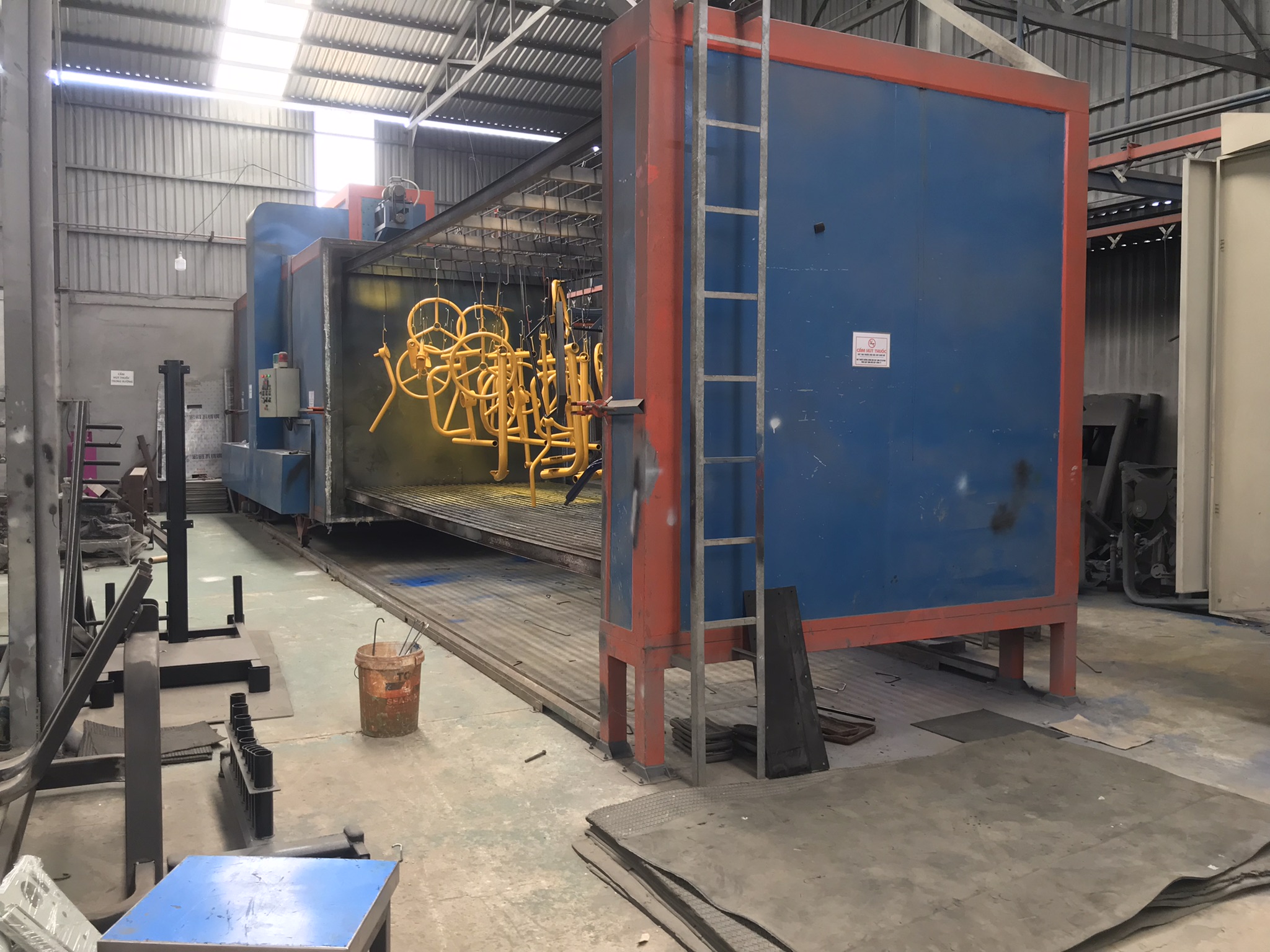
Define roughness values. For machined or ground surfaces, specify Ra (arithmetic average roughness). roughness values (Ra) 6 For sheet metal with standard finishes, Ra 1.6 µm is common for functional surfaces. Sandblasted or powder-coated finishes like those on heavy-duty mounting brackets have rougher profiles — typically Ra 3.2 to 6.3 µm.
-
List defect types and limits. Be explicit about what is allowed and what is not.
| Defect Type | Zone A (Visible) | Zone B (Semi-Visible) | Zone C (Hidden) |
|---|---|---|---|
| Scratches | Not allowed | ≤ 10 mm, max 2 per part | Allowed |
| Dents | Not allowed | ≤ 0.5 mm depth | Allowed if no function impact |
| Oxidation spots | Not allowed | Not allowed | Allowed if coated over |
| Weld marks | Smooth, flush | Visible but clean | Allowed |
| Tool marks | Not allowed | ≤ 5 mm length, light | Allowed |
| Powder coat runs/sags | Not allowed | Minor, ≤ 3 mm | Allowed |
-
Create limit samples. We keep golden samples — one at our inspection station, one at the supplier's factory. When inspectors disagree, both sides reference the same physical part.
-
Specify coating and plating requirements. For parts that undergo powder coating, anodizing, or plating, define adhesion test methods (cross-hatch tape test per ASTM D3359 7), minimum coating thickness, and salt spray test duration. We use 48-hour salt spray testing as our standard for corrosion resistance verification on steel parts.
Surface Finish and Functional Performance
Surface finish is not just cosmetic. Rough surfaces on mating faces cause poor seal performance. Burrs on edges injure assembly workers. Oxidation under coatings leads to premature failure. By defining these standards upfront in your quality control plan, you prevent arguments later and give inspectors clear, binary pass/fail criteria. Understanding the key quality inspection steps for finished sheet metal products helps ensure nothing is overlooked before parts ship.
How can I ensure my supplier's inspection results align with my drawing requirements?
One trade-off we weigh constantly is trust versus verification. We want to trust our suppliers, but we have seen too many cases where a supplier's internal inspection report says "all pass" while our own checks reveal out-of-spec parts. The gap usually comes down to method, not intent.
To ensure alignment, require your supplier to use the same measurement tools, methods, and datum references defined in your drawings. Conduct correlation studies between your inspection results and theirs, and mandate that suppliers submit First Article Inspection reports with actual measured values — not just pass/fail checkmarks.

The Root Cause of Measurement Disagreements
When our numbers and a supplier's numbers do not match, the problem is almost always one of three things: different measurement equipment, different datum references, or different environmental conditions. A caliper measures differently than a CMM. A part measured at 35°C in a factory reads differently than at 20°C in an air-conditioned lab.
A Practical Alignment Process
Here is the step-by-step method we use to align supplier quality with our requirements:
Step 1: Issue a clear inspection instruction document. This document specifies which tool to use for each dimension, where to place the datum, and what the acceptance criteria are. We attach annotated drawings — not just raw CAD files.
Step 2: Require actual measured values. Many suppliers submit inspection reports that only say "OK" or "NG." We require actual numbers. If the tolerance is 10.00 ±0.10 mm, we want to see "10.04 mm," not "Pass." This lets us track trends using SPC data for process capability and catch drift before it becomes a reject.
Step 3: Conduct a gauge R&R or correlation study. We send the same five parts back and forth. The supplier measures them; we measure them. We compare results. If the deviation between us is consistently above 10% of the tolerance band, we investigate the root cause — usually a tooling or fixturing difference.
Step 4: Audit the supplier's quality management system. During our supplier audits, we check whether they have documented incoming inspection procedures, calibrated equipment with valid certificates, and trained inspectors. An ISO 9001 certification 8 is a good starting point, but the real proof is on the shop floor.
Step 5: Require material certification traceability. Every lot must come with a Certificate of Conformance (CoC) or Mill Test Report (MTR) linked to a specific heat or lot number. We cross-reference the material certification data — chemical composition, tensile strength, hardness — against the drawing's material callout. For example, if the drawing calls SUS304, the MTR must confirm the chromium and nickel content falls within ASTM A276 ranges.
What Happens When Results Do Not Align
When we find discrepancies, we trigger a formal non-conformance handling process. The part gets placed on hold. We issue a Non-Conformance Report (NCR) and send it to the supplier with photos and measurement data. The supplier must respond with a root cause analysis and corrective action within an agreed timeframe. We track NCR closure rates as a key supplier performance metric.
| Alignment Issue | Likely Root Cause | Corrective Action |
|---|---|---|
| Dimension consistently 0.05 mm off | Different measurement datum | Align datum reference in inspection instruction |
| Hardness values differ | Different tester type (Rockwell vs. Vickers) | Standardize test method and conversion table |
| Surface finish dispute | No limit sample at supplier | Provide golden sample to supplier |
| MTR missing or incomplete | Supplier did not request from mill | Mandate MTR as shipping requirement in PO |
| Bend angle off by 1° | Measurement taken at wrong location | Add measurement point photo to inspection plan |
What AQL sampling levels should I set to manage the quality of my incoming sheet metal?
A lesson we learned the hard way: inspecting every single part in a 5,000-piece lot is neither practical nor cost-effective. But skipping inspection entirely is a gamble. The answer sits in the middle — statistically valid sampling based on Acceptable Quality Levels.
Set AQL sampling levels based on part criticality and risk. For critical dimensions, use AQL 1.0 with General Inspection Level II per ANSI/ASQ Z1.4. For cosmetic defects, use AQL 2.5. For minor defects, use AQL 4.0. Tighten inspection for new suppliers and loosen it for proven, consistently conforming ones.
Understanding AQL in Plain Terms
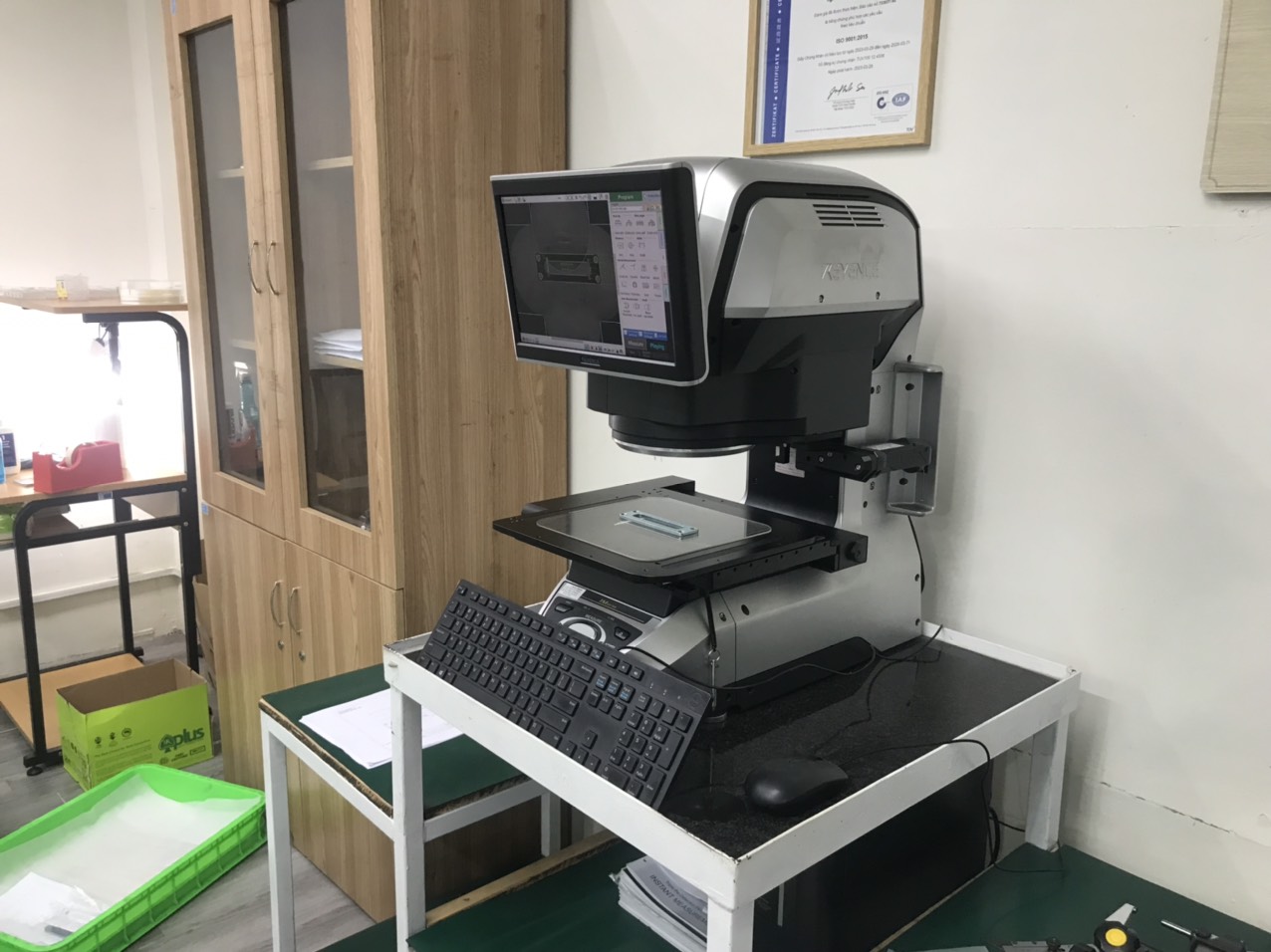
AQL stands for Acceptable Quality Level. It is a statistical tool, not a permission slip for defects. An AQL of 1.0 means you are willing to accept a lot where, statistically, no more than 1% of parts are defective. The sampling plan from ANSI/ASQ Z1.4 9 tells you exactly how many parts to pull from a lot and how many defects you can find before rejecting the entire lot.
How We Set AQL Levels by Defect Category
We classify defects into three categories and assign each a different AQL:
| Defect Category | Definition | AQL Level | Example |
|---|---|---|---|
| Critical | Causes safety risk or total function failure | 0 (100% inspection) | Cracked weld, wrong material |
| Major | Part will not assemble or meet specification | 1.0 | Hole position out of tolerance, thickness deviation > ±0.03 mm |
| Minor | Cosmetic issue, no functional impact | 2.5 – 4.0 | Light scratch on hidden surface, minor burr |
For a lot size of 500 parts at General Inspection Level II with AQL 1.0, the standard calls for a sample of 50 parts. If you find more than 1 defective part in those 50, you reject the lot.
Adjusting Inspection Levels Over Time
We do not keep every supplier on the same inspection level forever. ANSI/ASQ Z1.4 provides three switching rules:
- Normal to Tightened: If 2 out of 5 consecutive lots are rejected, switch to tightened inspection (larger sample size, stricter accept/reject numbers).
- Normal to Reduced: If 10 consecutive lots pass and the total defect count is low, you may switch to reduced inspection (smaller sample size).
- Tightened to Discontinued: If 5 consecutive lots under tightened inspection are still rejected, stop accepting material from that supplier until corrective action is verified.
This dynamic approach balances inspection cost with risk. New suppliers always start at normal or tightened. Proven suppliers earn reduced inspection — but they never earn full exemption. We always pull at least a small sample to maintain traceability and catch any process drift.
When to Go Beyond AQL
AQL-based sampling works well for attributes (pass/fail checks). But for variable data — like thickness measurements or bend angles — we supplement AQL with statistical process control. We collect actual measured values from each sample, calculate Cpk, and track trends over time. If Cpk drops below 1.33, we alert the supplier before the next shipment. This proactive approach prevents rejects rather than just detecting them.
Some clients also require us to coordinate third-party inspections at the supplier's factory. An independent inspector pulls random samples and sends them to a lab for salt spray testing, tensile testing, or hardness verification. This adds a layer of objectivity — especially useful when onboarding a new supplier or qualifying a new part.
Conclusion
Developing IQC inspection standards for sheet metal parts requires clear dimensional tolerances, objective surface finish criteria, supplier alignment procedures, and risk-based AQL sampling — all grounded in your engineering drawings and enforced consistently.
Frequently Asked Questions
What critical dimensions should I include in my sheet metal IQC checklist?
When we receive a new set of engineering drawings 2 from a U.S. client, the first thing our quality engineers do is highlight every dimension that directly affects fit, function, or assembly — because missing even one critical callout can cascade into a rejected shipment.
How do I define acceptable surface finish and cosmetic standards for my custom parts?
A buyer once told us: "The parts measured perfectly, but they looked terrible — scratches everywhere." That conversation taught us that surface finish inspection needs the same rigor as dimensional checks, especially for visible or coated components.
How can I ensure my supplier's inspection results align with my drawing requirements?
One trade-off we weigh constantly is trust versus verification. We want to trust our suppliers, but we have seen too many cases where a supplier's internal inspection report says "all pass" while our own checks reveal out-of-spec parts. The gap usually comes down to method, not intent.
Footnotes
1. Explains the importance and process of incoming quality control in manufacturing. ↩︎
2. Defines engineering drawings, their purpose, and standardization in technical communication. ↩︎
3. Describes CMMs as devices for measuring physical object geometry with high precision. ↩︎
4. Explains FAI reports as documentation verifying that production processes meet specifications. ↩︎
5. Details ISO 2768 as an international standard for general tolerances in engineering drawings. ↩︎
6. Defines Ra as the arithmetic average roughness, a key indicator of surface finish. ↩︎
7. Describes ASTM D3359 as a standard tape test method for evaluating coating adhesion. ↩︎
8. Explains ISO 9001 certification as demonstrating an organization’s quality management system compliance. ↩︎
9. Details ANSI/ASQ Z1.4 as a standard for acceptance sampling procedures and tables by attributes. ↩︎