Every week, our team reviews drawings from U.S. buyers who lost weeks — and thousands of dollars — because their CAD files broke when the overseas fabricator’s CAM system tried to read them.
To ensure CAD/CAM compatibility when sourcing sheet metal fabrication, use neutral data exchange formats like STEP for 3D models and DXF for flat patterns, verify your supplier’s CAM software and post-processor capabilities upfront, supply detailed 2D prints with explicit tolerances, and confirm design for manufacturability before production begins.
This article walks through the practical steps we follow at DEWIN when bridging the gap between a buyer’s design intent and a fabricator’s shop floor neutral data exchange formats 1. Each section tackles a specific compatibility challenge and gives you actionable checks you can apply today.
Which CAD file formats should I use to minimize errors during my sheet metal sourcing process?
A lesson we learned early in our sourcing work: a buyer sent a proprietary .SLDPRT file 2 to a Vietnamese fabricator who only ran Inventor STEP for 3D models 3. The file converted poorly, bend lines vanished, and the first sample was scrap.
Use STEP (.stp) for 3D model exchange and DXF or DWG for 2D flat patterns. These neutral data exchange formats are ISO-standard, broadly supported across CAD and CAM platforms, and preserve critical geometry far more reliably than proprietary file types during the sheet metal sourcing process.

Why Proprietary Formats Cause Problems
Proprietary files — SolidWorks .SLDPRT, Autodesk .IPT, CATIA .CATPart — contain feature trees and parametric data tied to a specific software version DXF for 2D flat patterns 4. When your supplier opens that file in a different program, the conversion engine must guess how to rebuild features. Bend allowance calculations, k-factor values, and even material thickness assignments can shift. The result is a flat pattern that does not match your intent.
The Neutral Format Hierarchy
Not all neutral formats are equal. Here is how the most common options compare for sheet metal work:
| Format | Best Use | Preserves Tolerances? | Preserves Bend Data? | Broad CAM Support |
|---|---|---|---|---|
| STEP (.stp) | 3D solid model exchange | No (geometry only) | Partial (geometry of bends) | Very high |
| DXF (.dxf) | 2D flat patterns, laser/punch profiles | No | N/A (flat pattern) | Very high |
| DWG (.dwg) | 2D drawings with GD&T callouts | Yes (in annotations) | N/A | High |
| IGES (.igs) | Legacy 3D surfaces | No | Poor | Moderate |
| Parasolid (.x_t) | 3D solid exchange (Siemens ecosystem) | No | Partial | Moderate |
| Native (.SLDPRT, .IPT) | Internal design only | Yes (within same software) | Yes (within same software) | Low |
The 3D-Plus-2D Rule
One debate we encounter repeatedly is whether a 3D model alone is enough. In our experience coordinating between U.S. engineering teams and Asian fabricators, it is not — at least not for sheet metal. A STEP file gives the fabricator accurate geometry for nesting optimization and CNC programming, but it does not carry tolerance callouts, surface finish notes, or hardware insertion specs. You need a supplemental 2D print in DXF or DWG (or a PDF with GD&T) to lock down every dimension that matters.
Send both. The 3D file drives the CAM system. The 2D print is the contractual reference for inspection. This dual-file approach eliminates the single biggest source of interpretation errors we see in cross-border fabrication projects.
Quick Checklist Before You Send Files
- Export your 3D model as STEP AP214 or AP242 for maximum fidelity.
- Flatten your part inside your own 3D modeling software first so you can verify the flat pattern.
- Export the flat pattern as a separate DXF layer.
- Include a dimensioned 2D drawing with material thickness, bend radii, and tolerances.
- Zip everything into one package with a clear naming convention that includes revision number.
How do I confirm my offshore supplier has the right CAM software to match my design specifications?
During a recent supplier audit in Vietnam, we discovered a shop marketing "full CAD/CAM capability" was actually programming its laser cutter with manually traced DXF outlines and zero nesting optimization. The parts came out fine for simple rectangles — but failed on complex brackets with tight cutout tolerances.
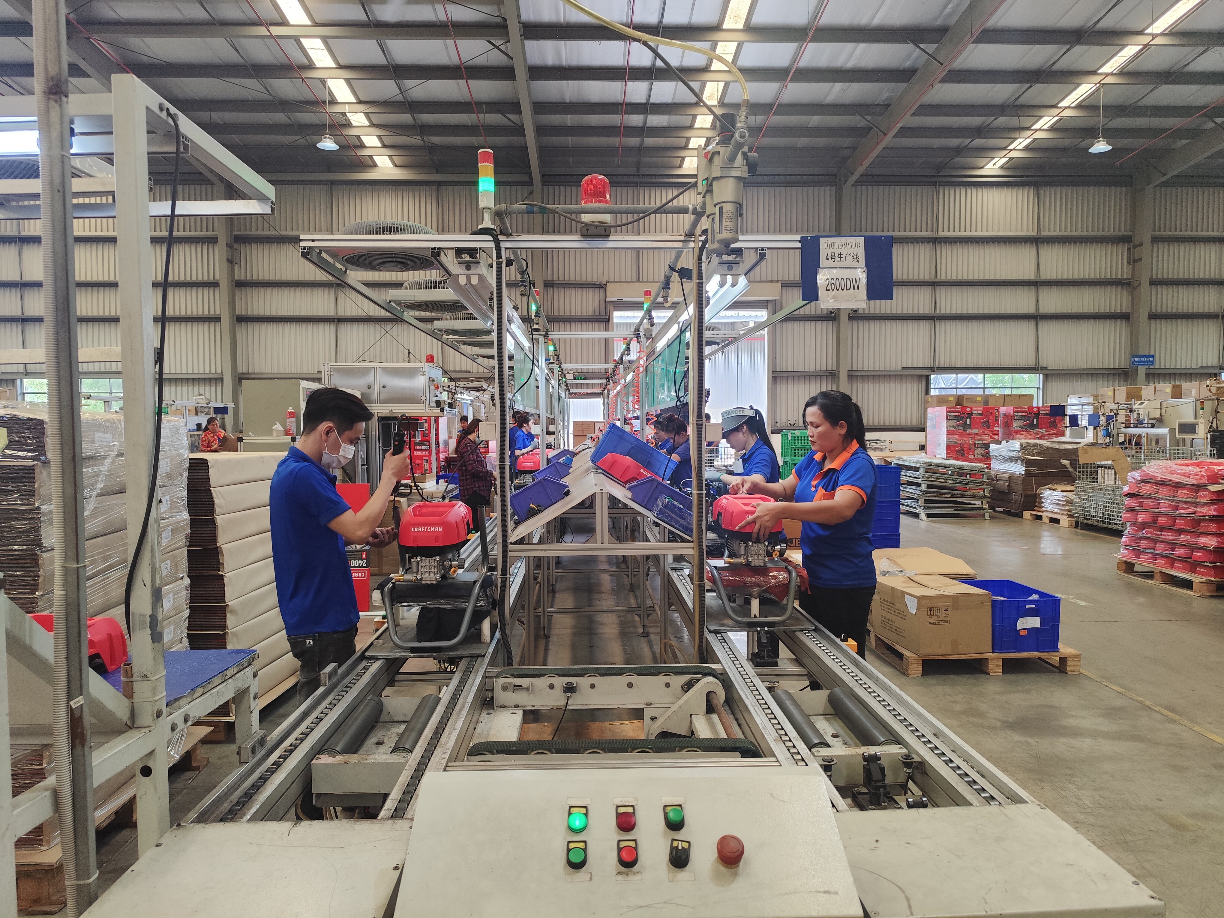
Before awarding a contract, request the specific CAM software name and version your supplier uses, ask for sample tool-path screenshots or nesting reports for a similar part, and verify that their post-processor is calibrated for the exact CNC equipment — laser, punch, or waterjet — that will produce your parts.
What to Ask in a Technical Questionnaire
Do not rely on a supplier's general capability statement. Send a focused questionnaire. Here are the questions we include in every DEWIN supplier qualification:
| Question | Why It Matters |
|---|---|
| What CAM software do you use? (Name, version) | Confirms software integration capability with your CAD output |
| Can you import STEP and DXF files directly? | Tests whether they need manual re-drawing, which adds error risk |
| What CNC machines will run my parts? (Brand, model) | Needed to verify the post-processor matches the machine controller |
| Do you use automatic nesting? | Nesting optimization affects material yield, cost, and lead time |
| Can you show a sample nesting report or tool-path preview? | Proves the CAM workflow is functional, not theoretical |
| Do you perform digital prototyping or simulation before cutting? | Reveals whether they catch collision or clearance issues pre-production |
Understanding the Post-Processor Link
A CAM program generates generic tool paths. The post-processor translates 6 those paths into G-code specific 7 to a machine's controller — whether it is a Fanuc, Siemens, Mazak, or Mitsubishi unit. If the post-processor is wrong or poorly configured, the machine may cut at the wrong feed rate, skip pierce points, or crash. We always verify that the fabricator has a validated post-processor for every machine that will touch our buyer's parts.
Software Silos Are a Red Flag
Some shops use one program for laser cutting, a different one for CNC punching, and yet another for press brake bending. Each transfer between software is a chance for data loss. The trend in the industry is toward all-in-one CAD/CAM platforms — like Sigmanest, Lantek, or Radan — that handle profiling, nesting, and bending in a single environment. When we audit a supplier, we look for this kind of unified manufacturing workflow. Shops that have eliminated software silos tend to deliver more consistent first-article results.
Cloud vs. Local CAM Software
Cloud-based CAM is growing, especially for collaborative design reviews. However, most shop-floor CNC programming still runs locally because machine controllers need instant, low-latency communication. A supplier that uses a cloud platform for quoting and review but runs local CAM for production is following current best practice. Be cautious of shops that claim to run everything in the cloud but cannot demonstrate offline processing capability.
What can I do to ensure my critical drawing tolerances are preserved throughout the digital manufacturing workflow?
One of our U.S. buyers once asked why a ±0.1 mm hole position on their drawing arrived as ±0.3 mm on the first article. The investigation revealed the tolerance note existed only on page three of a PDF. The fabricator's CAM operator never saw it because he worked exclusively from the STEP file.
To preserve critical sheet metal tolerances, embed key dimensions in both your 3D model annotations and your 2D drawing, require the fabricator to submit a PPAP or first-article inspection report referencing each critical dimension, and specify inspection methods — such as CMM or fixture gauges — so nothing is left to interpretation.
Where Tolerances Get Lost
Tolerance data can vanish at several handoff points. Understanding these points helps you build safeguards.
- CAD to neutral file export. When you save to STEP, tolerance annotations are stripped. Only raw geometry survives. This is the most common loss point.
- CAM operator interpretation. If the operator works only from the 3D model, they assume standard tolerances — which may be looser than your design requires.
- Nesting and cutting. Thermal distortion during laser cutting can shift features. Without explicit callouts, the operator may not compensate.
- Bending sequence. Cumulative bend errors stack up. If bend allowance values in the CAM software differ from those in your CAD model, final dimensions drift.
A Practical Tolerance Communication Framework
| Step | Action | Owner | Document |
|---|---|---|---|
| 1 | Mark critical dimensions with a balloon or flag in the 2D drawing | Buyer's engineer | 2D DWG/PDF |
| 2 | Create a Critical-to-Quality (CTQ) list with dimension ID, nominal, tolerance, and inspection method | Buyer | Excel or CTQ sheet |
| 3 | Review CTQ list with the fabricator before quoting | Both | Meeting notes / email |
| 4 | Fabricator confirms achievable tolerances and flags any at-risk dimensions | Supplier | Formal reply |
| 5 | Produce first article and inspect against CTQ list | Supplier + DEWIN QC | First Article Inspection Report 8 (FAIR) |
| 6 | Buyer approves FAIR before mass production | Buyer | Signed FAIR |
Design for Manufacturability and Tolerances
Design for manufacturability 9 plays a direct role in tolerance preservation. If you specify a ±0.05 mm tolerance on a dimension that spans two bends, you are asking the fabricator to absorb cumulative bend error — which may not be physically possible on a standard press brake. Our engineering team flags these situations during the co-development phase. We recommend relaxing non-functional tolerances and tightening only those dimensions that truly affect fit or performance.
Bend allowance accuracy is another factor. Different 3D modeling software packages calculate bend allowance differently based on k-factor assumptions. If your k-factor is set to 0.40 and the fabricator's CAM uses 0.44, the flat pattern will differ. Specify the k-factor in your drawing notes so both sides work from the same number.
Version Control Prevents Tolerance Confusion
Implement clear version control. Name files with a revision code — for example, BracketAssy_Rev_C.stp. Maintain a log of what changed between revisions. When a fabricator works from an outdated file, tolerance changes from the latest revision are obviously lost. We manage a shared document tracker for every project to ensure the shop floor always has the current file.
How do I evaluate a supplier's technical team to ensure they can handle my complex custom part designs?
A trade-off we weigh on every new sourcing project is speed versus depth of supplier evaluation. A quick email exchange tells you almost nothing about a fabricator's real engineering capability. The only way to know is to test them — with a real part, under real conditions.
Evaluate a supplier's technical team by submitting a complex sample part for quoting and first-article production, reviewing their DFM feedback quality, assessing their engineers' ability to read and question your drawings, and auditing their shop-floor CAM programming and inspection processes in person or via video.
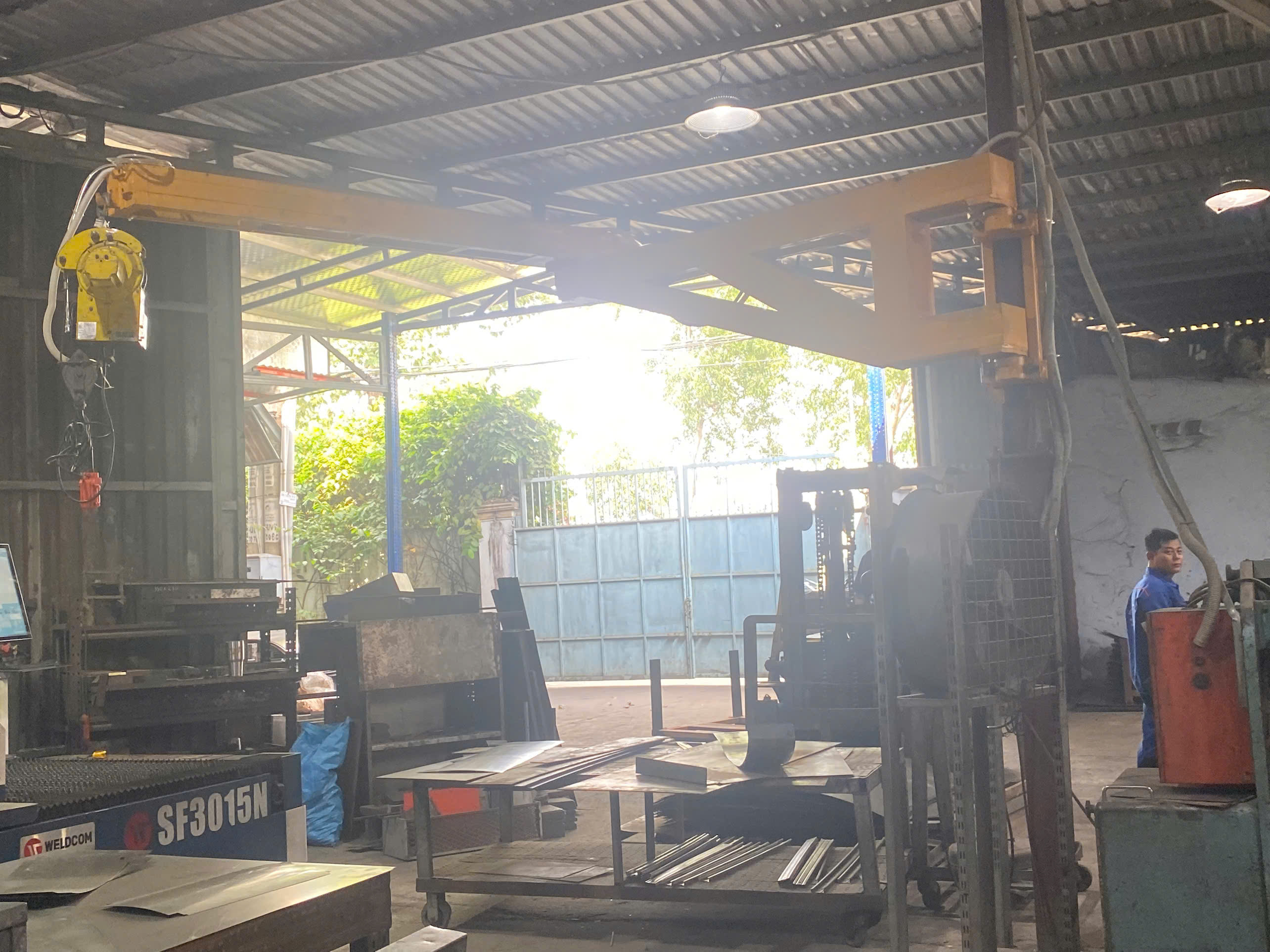
The DFM Feedback Test
The fastest way to gauge a technical team is to send a deliberately challenging drawing and see how they respond. Include features like a tight bend radius near a hole, an unusual material thickness, or a tolerance that pushes the limits of standard equipment. A strong team will come back with specific questions and alternative suggestions. A weak team will simply quote the part without comment — and later deliver a non-conforming sample.
When we onboard a new fabricator for DEWIN's supply chain, we grade their DFM response on several criteria:
- Completeness: Did they address every feature, or only the easy ones?
- Technical accuracy: Are their bend radius and clearance recommendations correct for the specified material?
- Communication clarity: Can they explain the issue in simple terms, or do they send vague one-liners?
- Proactiveness: Did they suggest cost-saving alternatives without being asked?
Assessing CAM Programming Skill
A capable CAM programmer does more than import a file and click "generate." They make decisions about cut sequence, lead-in/lead-out strategy, micro-joint placement, and common-line cutting. These choices affect part quality, especially on complex brackets with multiple cutouts and irregular geometry — like the mirrored mounting brackets with angular folds, weld joints, and multiple mounting holes that we regularly source for industrial clients.
Ask the supplier to walk you through a sample CNC programming session on video. Watch for:
- Do they inspect the imported geometry before nesting?
- Do they set proper lead-ins to avoid blemishes on visible surfaces?
- Do they account for material grain direction?
- Do they verify the flat pattern against your supplied DXF?
On-Site or Video Audit Essentials
If you cannot visit in person, a structured video audit works. Our team in Vietnam conducts these regularly. Focus on three areas:
- Engineering office: Look at their software licenses, monitor setups, and how drawings are stored and controlled.
- Shop floor: Watch a part go from CAM file to machine to inspection bench. Ask the operator to explain what they are doing.
- Quality lab: Confirm they own calibrated measuring tools — calipers, CMM, height gauges, pin gauges — and that they use them against a documented inspection plan.
A supplier who can handle complex custom parts has a team that asks questions, catches errors before cutting, and uses digital prototyping when geometry is uncertain. That combination is far more valuable than a long equipment list.
Conclusion
CAD/CAM compatibility is not a software problem alone — it is a process discipline that spans file formats, tolerance communication, CAM verification, and technical team evaluation. Build these checks into your sourcing workflow, and you will get conforming parts on the first attempt far more often.
Frequently Asked Questions
Which CAD file formats should I use to minimize errors during my sheet metal sourcing process?
A lesson we learned early in our sourcing work: a buyer sent a proprietary .SLDPRT file 2 to a Vietnamese fabricator who only ran Inventor STEP for 3D models 3 . The file converted poorly, bend lines vanished, and the first sample was scrap.
How do I confirm my offshore supplier has the right CAM software to match my design specifications?
During a recent supplier audit in Vietnam, we discovered a shop marketing "full CAD/CAM capability" was actually programming its laser cutter with manually traced DXF outlines and zero nesting optimization. The parts came out fine for simple rectangles — but failed on complex brackets with tight cutout tolerances.
What can I do to ensure my critical drawing tolerances are preserved throughout the digital manufacturing workflow?
One of our U.S. buyers once asked why a ±0.1 mm hole position on their drawing arrived as ±0.3 mm on the first article. The investigation revealed the tolerance note existed only on page three of a PDF. The fabricator's CAM operator never saw it because he worked exclusively from the STEP file.
Footnotes
1. Explains the importance and types of neutral data exchange formats in CAD/CAM systems. ↩︎
2. Replaced HTTP 404 link with a relevant Xometry resource detailing the .SLDPRT file format. ↩︎
3. Provides detailed information on the STEP file format for 3D model exchange and interoperability. ↩︎
4. Explains the DXF file format, commonly used for 2D flat patterns in sheet metal manufacturing. ↩︎
5. Provides context and details about the ISO standard for product data representation and exchange. ↩︎
6. Details the function of a post-processor in translating CAM tool paths into machine-specific G-code. ↩︎
7. Explains G-code, the programming language for CNC machines, and its role in manufacturing. ↩︎
8. Describes the purpose and components of a First Article Inspection Report (FAIR) in manufacturing. ↩︎
9. Explains the principles and importance of Design for Manufacturability (DFM) in product development. ↩︎