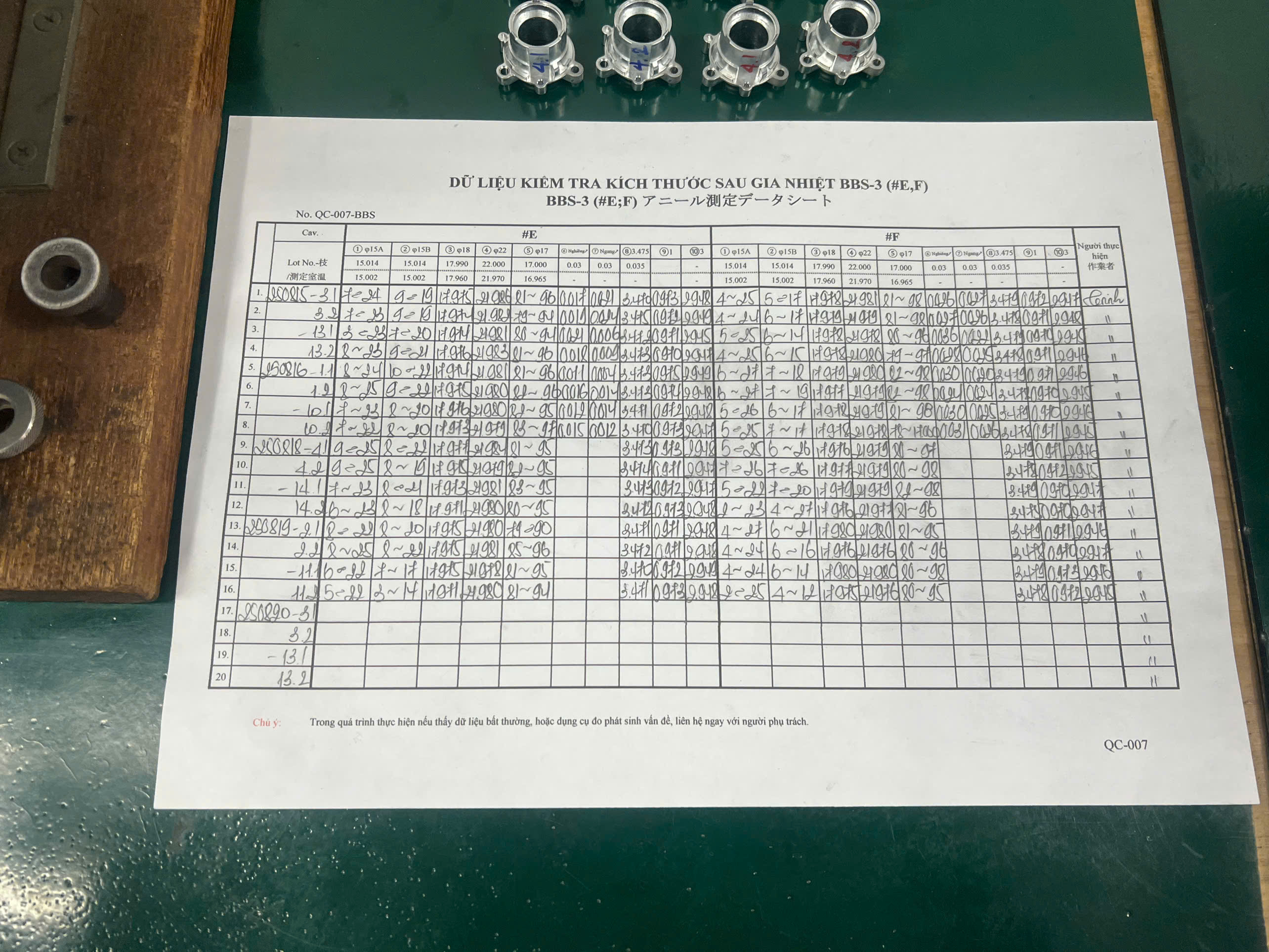

When our engineering team reviewed a batch of mounting brackets destined for a U.S. industrial platform, we found hairline cracks along the bend lines — a problem invisible to the naked eye but catastrophic under load. The client had sourced these from a previous supplier who skipped bend radius checks 1 entirely. That single oversight could have meant structural failure on an elevated walkway. This is the kind of risk that keeps purchasing managers up at night, and it’s exactly why safety for sheet metal fabricated parts in load-bearing structures 2 demands relentless attention from design through delivery.
Safety for sheet metal fabricated parts in load-bearing structures requires strategic material selection, optimized bend radii, robust joining methods, strict quality control processes like PPAP, non-destructive testing, and validated structural testing reports — all coordinated between buyer and supplier to achieve “right first time” results.
This article walks through the critical decisions you face when sourcing load-bearing sheet metal components from Asian manufacturing partners. We cover material grades, quality systems, welding and bending verification, and the testing reports that protect your end users — and your reputation.
How do I choose the right material grade to ensure my sheet metal parts meet specific load-bearing requirements?
A lesson we learned early in our contract manufacturing work: the wrong steel grade doesn't just underperform — it fails unpredictably. One client specified a generic "stainless steel" on their drawing without calling out the grade, and the supplier defaulted to a lower-carbon variant with insufficient tensile strength 3 for the application.
Choose the right material grade by matching the part's expected load, environment, and fatigue life to specific alloy properties — tensile strength, yield strength, corrosion resistance, and formability — then validate the grade with mill certificates and incoming material inspection before production begins.
Why Material Selection Is the Foundation of Structural Integrity
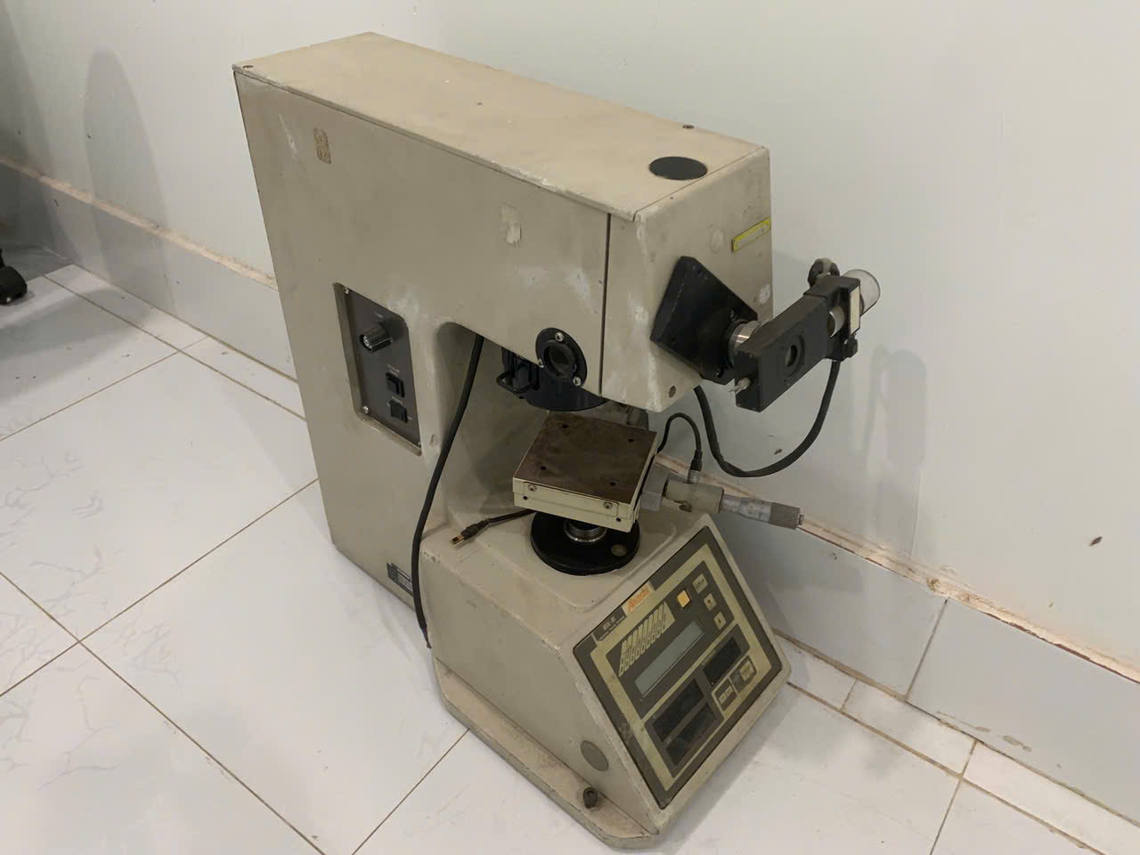
Material selection is not a checkbox. It is the single decision that sets the ceiling on your part's performance. A bracket that holds a cable tray in a dry warehouse faces different demands than a mounting plate on an offshore platform. The load type matters. The environment matters. The duty cycle matters.
When we co-develop parts with clients, we start by asking three questions: What is the maximum static load? Will the part see cyclic or dynamic loading? And what is the operating environment — temperature, humidity, chemical exposure?
Common Material Grades for Load-Bearing Sheet Metal
| Material | Typical Grade | Tensile Strength (MPa) | Best For | Key Limitation |
|---|---|---|---|---|
| Hot-Rolled Steel | ASTM A36 | 400–550 | Structural brackets, platforms | Low corrosion resistance without coating |
| Stainless Steel | 304 / 316 | 515–620 | Food, marine, chemical environments | Higher cost, work-hardening during forming |
| Aluminum Alloy | 5052-H32 | 228 | Lightweight enclosures, housings | Lower strength; not for heavy loads |
| Galvanized Steel | SGCC / DX51D | 270–500 | Outdoor structures, HVAC supports | Zinc layer can crack at tight bends |
| High-Strength Low-Alloy | ASTM A572 Gr 50 | 450–620 | Heavy-duty frames, structural supports | Requires controlled bending parameters |
Material Thickness and Its Role in Load Capacity
Material thickness directly determines load capacity. Sheet metal parts range from 0.9 mm to 20 mm. For load-bearing applications, we rarely work below 2 mm. The critical thing is that thickness must be uniform across the part. Variations in thickness create unpredictable stress concentrations and can cause localized failure modes that are almost impossible to detect visually.
We always request mill certificates 4 (also called material test reports) from the steel supplier. These certificates confirm the chemical composition and mechanical properties of the specific heat of material used. Without a mill cert, you are guessing. And guessing has no place in structural safety.
Corrosion Resistance and Long-Term Safety
A part that meets its tensile strength requirement on day one but corrodes over 18 months is not a safe part. We factor corrosion resistance into every material decision. For outdoor or humid environments, stainless steel 316 or hot-dip galvanized steel is standard. Protective coatings — powder coat, zinc plating, or e-coat — add another layer of defense.
The bottom line: specify the grade, verify with documentation, and match the material to the real-world conditions the part will face.
What quality control and PPAP processes should I expect from my supplier to guarantee structural safety?
The most frustrating pattern we see from U.S. purchasing managers: they receive parts that look fine but fail under load because the supplier never ran in-process checks. The drawing called out critical dimensions and tolerances, but nobody measured them during production. Our Vietnam and China teams have learned that for load-bearing components, quality cannot be inspected in at the end — it must be built in from the start.
Expect a full PPAP submission (including control plans, process flow diagrams, MSA, capability studies, and first article inspection reports), combined with in-process dimensional checks, material traceability, and final inspection against your drawing's critical-to-quality characteristics.

What PPAP Means for Structural Sheet Metal Parts
PPAP — Production Part Approval Process — is not just an automotive requirement. PPAP processes 5 It is the most reliable framework for proving a supplier can consistently produce parts that meet your specification. For load-bearing sheet metal, PPAP gives you documented evidence that the supplier understands your design intent, has validated their process, and can repeat results.
Here is what a meaningful PPAP submission should include for structural parts:
| PPAP Element | What It Proves | Why It Matters for Load-Bearing Parts |
|---|---|---|
| Design Records | Supplier has the correct revision of the drawing | Prevents production to outdated specs |
| Process Flow Diagram | Steps from raw material to shipping are defined | Identifies where defects could be introduced |
| Control Plan 6 | Critical dimensions are measured at defined intervals | Ensures bend angles, hole positions, and weld quality are monitored |
| MSA (Measurement System Analysis) | Gauges and instruments are accurate and repeatable | Prevents false pass/fail readings on critical features |
| Dimensional Results | First article measurements vs. drawing tolerances | Confirms the process produces conforming parts |
| Material Certifications | Grade and properties match the spec | Validates tensile strength, hardness, and composition |
| Capability Study (Cpk) | Process is statistically capable | Shows the process stays within tolerance consistently, not just on a sample |
In-Process vs. Final Inspection
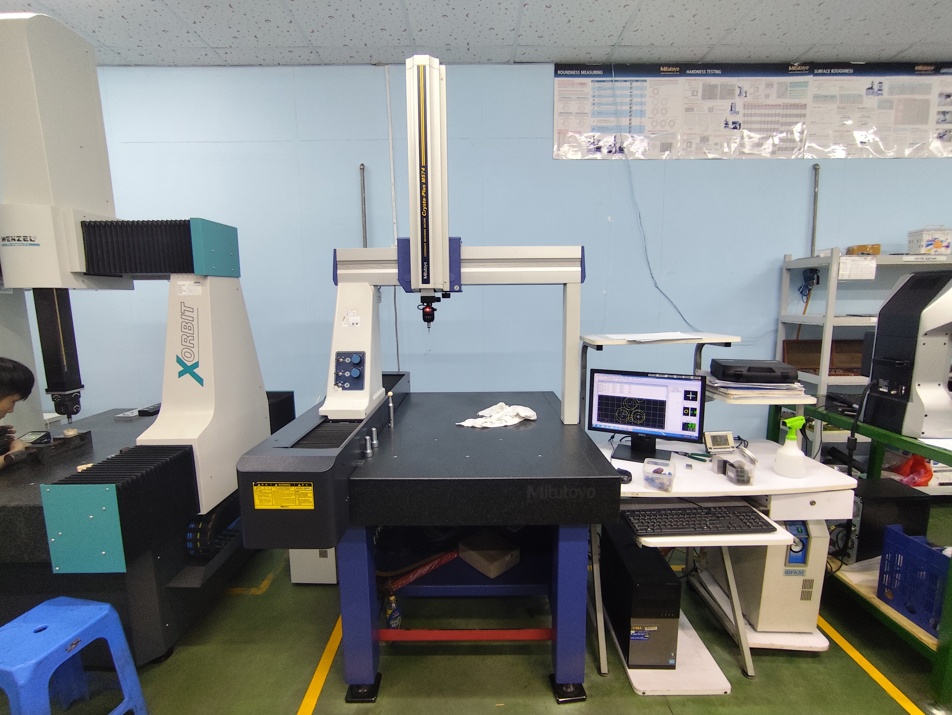
Final inspection alone is not enough. If a brake press drifts 0.5° on a bend angle mid-run, you may not catch it until hundreds of parts are non-conforming. In-process inspection — checking parts at defined intervals during production — catches drift early. Our quality engineers on the ground in Vietnam and China perform these checks using calibrated instruments and report results in real time.
Traceability: Connecting Every Part to Its Source
For structural safety, every part must be traceable back to its raw material lot, production date, and inspection record. If a failure occurs in the field, traceability lets you isolate the affected batch and determine root cause. Without it, you face a full recall instead of a targeted one.
The design guidelines you set in your drawing are only as good as the quality system that enforces them. PPAP is the mechanism that closes that gap.
How can I verify that the welding and bending techniques used won't weaken my load-bearing components?
During a recent supplier audit at a factory in Vietnam, our process engineer noticed the welder was using a wire feed speed setting that didn't match the WPS (Welding Procedure Specification 7). The welds looked acceptable visually, but cross-section analysis later revealed incomplete fusion at the root — a classic hidden failure mode in load-bearing joints. This is why verification must go beyond visual checks.
Verify welding and bending quality by requiring qualified Welding Procedure Specifications (WPS), welder certifications, bend test coupons, non-destructive testing (ultrasonic, dye penetrant, or X-ray), and dimensional inspection of bend angles and radii against the design specification.
Bending: Where Structural Integrity Starts — or Ends
Bending is the most common forming operation in sheet metal fabrication. It is also where many structural problems originate. If the bend radius is too tight, the outer surface cracks. If the bend height is too short, the part deforms under load. The formula is straightforward:
Bend Height (H) = 2t + r
Where t is material thickness and r is the bend radius. This minimum ensures the die engages enough material to create a stable bend. The bend radius itself should be at least equal to the material thickness. Anything tighter risks cracking, especially in high-strength or work-hardened materials.
Flange length must be at least four times the material thickness. Short flanges slip during forming and produce inconsistent angles. Standard bend angle tolerance is ±1 degree, but for load-bearing assemblies, tighter tolerances may be needed — and must be called out on the drawing.
Reinforcement Techniques That Matter
Hem bends, gussets, and ribs all increase stiffness and resistance to deformation. A hem bend — folding the material 180° over itself — doubles the edge thickness and prevents twisting under perpendicular forces. Triangular gussets welded into corners distribute load across a larger area and prevent the joint from opening under stress. These are not decorative features. They are engineering requirements for load-bearing parts.
Welding Quality: What to Demand
Welding quality in load-bearing structures is non-negotiable. Here is what we require from every supplier:
-
Welding Procedure Specification (WPS): A documented procedure that defines the welding process, filler material, shielding gas, voltage, amperage, travel speed, and preheat requirements. The WPS must be qualified by destructive testing.
-
Welder Qualification Records (WQR): Proof that the individual welder has passed qualification tests for the specific process and position required.
-
Non-Destructive Testing (NDT): For critical welds, we require dye penetrant testing, ultrasonic testing, or radiographic testing. Non-Destructive Testing (NDT) 8 The choice depends on the joint type and criticality.
-
Destructive Testing on Coupons: Bend tests and tensile tests on sample weld coupons confirm the joint's mechanical properties meet the base material's requirements.
Comparing Joining Methods for Load-Bearing Applications
| Joining Method | Strength | Disassembly | Best Application | Risk |
|---|---|---|---|---|
| MIG Welding | High | No | Structural brackets, frames | Distortion, incomplete fusion if poorly controlled |
| TIG Welding | Very High | No | Thin-gauge precision parts, stainless steel | Slower, higher skill requirement |
| Riveting | Moderate | Difficult | Lightweight assemblies, shear-loaded joints | Hole weakens base material |
| Bolting | Moderate–High | Yes | Modular structures, maintenance-access points | Loosening under vibration; thread pull-out risk |
| Clinching | Low–Moderate | No | Non-structural panels, enclosures | Not suitable for high-load applications |
For load-bearing applications, welding generally provides the strongest joints. But welding also introduces the highest risk if done improperly. Stress concentrations around welds are common failure initiation points, especially under fatigue loading. This is why weld quality verification — not just visual, but through NDT and destructive testing — is essential.
Which structural testing reports should I request from my Asian manufacturing partner to ensure "right first time" results?
A trade-off we weigh on every project: how much testing is enough versus how much adds cost without adding safety? The answer depends on the consequences of failure. For a decorative panel, a dimensional report suffices. For a load-bearing bracket on an elevated platform, you need proof that the part will perform under the loads it was designed for — before it ever reaches the job site.
Request first article inspection reports (FAIR), material test reports (MTRs), dimensional inspection reports with GD&T callouts, weld inspection records (visual and NDT), load or proof testing results, and fatigue testing data for cyclically loaded components.
The "Right First Time" Testing Package
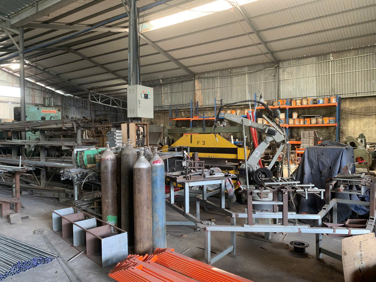
"Right first time" is not a slogan — it is a measurable outcome. It means the first production batch conforms to every drawing requirement, passes all functional tests, and ships on time without rework. Achieving this requires the supplier to validate the product and the process before full production begins.
Here is the testing documentation package we recommend for load-bearing sheet metal parts:
First Article Inspection Report (FAIR)
The FAIR is a complete dimensional verification of a sample part against every dimension and tolerance on the drawing. For structural parts, we use AS9102 or PPAP Level 3 format. Every measurement is recorded, compared to the specification, and marked pass or fail. This is your baseline proof that the tooling, fixturing, and process produce a conforming part.
Load and Proof Testing
For parts that bear specific loads, request proof testing. This means applying the rated load (or a safety factor multiplied load, typically 1.5× to 2×) to the actual part and confirming it does not yield, crack, or permanently deform. The test setup, applied load, and results should be documented with photographs and a signed report.
Fatigue Testing for Cyclic Loads
If your part experiences repeated loading and unloading — vibration, thermal cycling, or mechanical oscillation — fatigue testing is critical. Fatigue Testing for Cyclic Loads 9 Fatigue failure occurs at stress levels well below the material's ultimate tensile strength. The supplier should provide fatigue testing data or, at minimum, a fatigue life prediction based on Finite Element Analysis (FEA) and the material's known fatigue limits.
FEA and Simulation Reports
Advanced simulation tools like Finite Element Analysis allow engineers to predict stress distribution, identify failure points, and optimize geometry before cutting metal. We increasingly see U.S. clients requesting FEA reports as part of the co-development phase. These reports show where stress concentrations exist and whether the design meets required safety factors under various load scenarios.
What Building Codes and Standards Apply?
Depending on the application, your parts may need to comply with building codes, OSHA regulations, ANSI standards, or industry-specific requirements. Platforms and walkways must meet OSHA height, clearance, and non-slip surface requirements. Machine guards must comply with ANSI/NFPA standards. Your supplier should understand which standards apply and design accordingly.
Checklist: Reports to Request from Your Supplier
- Mill Test Reports (MTRs) for raw material
- First Article Inspection Report 10 (FAIR)
- Dimensional inspection report with GD&T
- Weld inspection records (visual + NDT)
- Proof/load test report with safety factor
- Fatigue test data or FEA simulation report
- PPAP package (if applicable)
- Coating thickness and adhesion test report
- Traceability matrix linking parts to material lots
The cost of requesting these reports upfront is a fraction of the cost of a field failure. Every report in this list exists to prevent a specific failure mode. Skip one, and you leave a gap in your safety assurance.
Conclusion
Safety for sheet metal fabricated parts in load-bearing structures depends on disciplined material selection, verified forming and joining processes, robust PPAP documentation, and comprehensive structural testing. Partner with a supplier who treats these steps as non-negotiable — because structural failure is never acceptable.
Frequently Asked Questions
What Building Codes and Standards Apply?
Depending on the application, your parts may need to comply with building codes, OSHA regulations, ANSI standards, or industry-specific requirements. Platforms and walkways must meet OSHA height, clearance, and non-slip surface requirements. Machine guards must comply with ANSI/NFPA standards. Your supplier should understand which standards apply and design accordingly.
How do I choose the right material grade to ensure my sheet metal parts meet specific load-bearing requirements?
A lesson we learned early in our contract manufacturing work: the wrong steel grade doesn't just underperform — it fails unpredictably. One client specified a generic "stainless steel" on their drawing without calling out the grade, and the supplier defaulted to a lower-carbon variant with insufficient tensile strength 3 for the application.
What quality control and PPAP processes should I expect from my supplier to guarantee structural safety?
The most frustrating pattern we see from U.S. purchasing managers: they receive parts that look fine but fail under load because the supplier never ran in-process checks. The drawing called out critical dimensions and tolerances, but nobody measured them during production. Our Vietnam and China teams have learned that for load-bearing components, quality cannot be inspected in at the end — it must be built in from the start.
Footnotes
1. Explains how correct bend radius prevents material failure and ensures part performance. ↩︎
2. Provides a comprehensive definition and explanation of load-bearing structures. ↩︎
3. Defines tensile strength as maximum pulling stress a material withstands before failure. ↩︎
4. Defines mill test certificates as documents verifying chemical and physical material properties. ↩︎
5. Replaced HTTP 404 with a comprehensive guide to the Production Part Approval Process (PPAP) from Quality-One, a recognized quality consulting firm. ↩︎
6. Defines Control Plan as a document outlining actions to ensure process outputs conform to requirements. ↩︎
7. Defines WPS as a formal document describing welding procedures for quality production welds. ↩︎
8. Explains NDT as evaluation techniques for materials without causing damage. ↩︎
9. Explains fatigue testing as a procedure to predict durability of parts under cyclic loading. ↩︎
10. Replaced HTTP 404 with a comprehensive guide to First Article Inspection (FAI) and its reports from 1factory. ↩︎