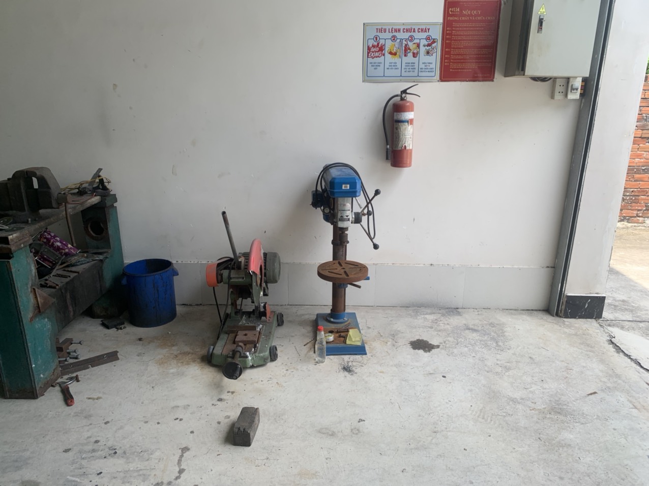
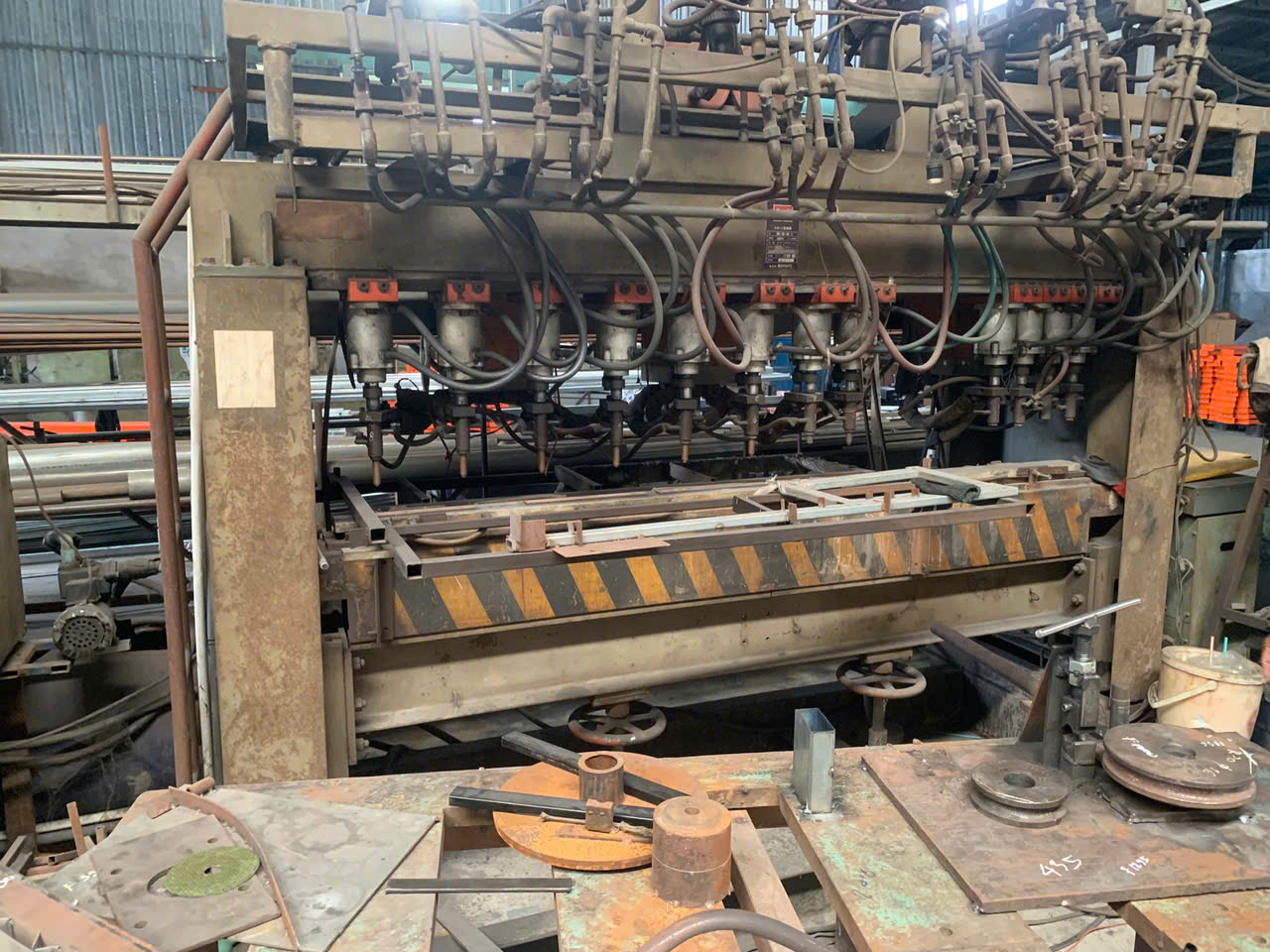
When our engineering team reviewed a batch of wind turbine mounting brackets returned from a coastal site in Texas, the root cause was clear — poor material selection and inadequate coating had allowed salt spray to eat through critical joints in under eighteen months. That failure cost the client six figures in downtime and replacement parts. Sheet metal fabrication 1 for energy projects demands more than basic metalworking; it demands a systems-level understanding of how weather attacks metal over decades.
Sheet metal fabrication for energy projects withstands extreme weather when engineers combine proper alloy selection, precision tolerances, advanced protective coatings, and stress-optimized designs — all validated through rigorous quality control at every fabrication stage to ensure corrosion resistance and long-term structural integrity.
This guide breaks down the critical decisions you need to make — from choosing the right alloy and coating system to selecting a fabricator who truly understands renewable energy infrastructure. Each section addresses a specific challenge and gives you actionable steps.
How do I choose the right alloy and coating to protect my sheet metal components from salt spray and high humidity?
A buyer we work with in the Gulf Coast region once asked us to quote two versions of the same solar panel mounting bracket — one in standard carbon steel and one in 316L stainless 2. The price difference was significant. But when we ran a total cost of ownership analysis over the expected 25-year service life, the stainless option was actually cheaper because it eliminated two full coating replacement cycles and avoided structural failure risk.
To protect sheet metal components from salt spray and high humidity, select marine-grade alloys like 316 stainless steel or 5052 aluminum, then apply a duplex coating system combining hot-dip galvanizing with powder coating for layered corrosion resistance that can exceed 25 years of outdoor service.
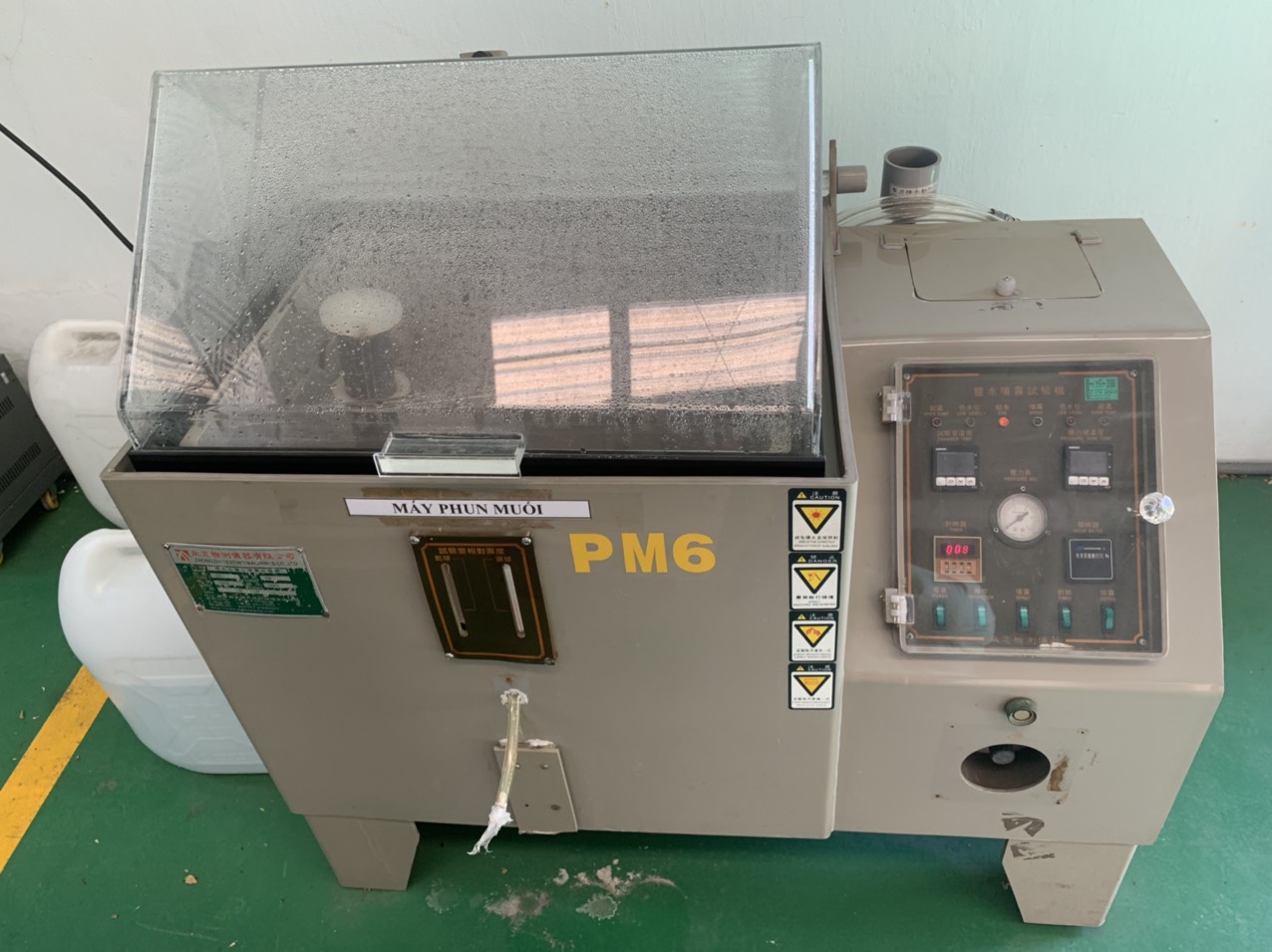
Understanding the Corrosion Threat
Salt spray and high humidity are among the most aggressive environmental factors for sheet metal. Sodium chloride ions penetrate surface films and accelerate oxidation. In marine and near-shore environments — common for wind energy installations — the corrosion rate of unprotected carbon steel can exceed 0.1 mm per year. Over a 20-year project life, that translates to significant material loss and compromised structural integrity.
The key is to match your material selection to the specific exposure conditions. Not every energy project needs the most expensive alloy. A solar farm in Arizona faces UV and thermal expansion challenges, not salt. A hydroelectric gate in the Pacific Northwest deals with constant freshwater immersion and biological fouling. Each scenario demands a different approach.
Alloy Comparison for Harsh Environments
| Alloy | Best For | Corrosion Resistance | Relative Cost | Typical Energy Application |
|---|---|---|---|---|
| 304 Stainless Steel | Moderate humidity, inland | Good | Medium | Solar panel frames, HVAC ductwork |
| 316/316L Stainless Steel | Salt spray, marine | Excellent | High | Offshore wind brackets, coastal infrastructure |
| Duplex Stainless Steel | Severe marine + high stress | Superior | Very High | Subsea energy components, tidal systems |
| 5052 Aluminum | Lightweight + moisture | Very Good | Medium | Solar mounts, lightweight enclosures |
| Galvanized Carbon Steel | Cost-sensitive inland | Moderate | Low | Ground-mount solar, utility enclosures |
| Corten (Weathering Steel) | Atmospheric exposure | Good (forms protective patina) | Low-Medium | Structural supports, non-immersion applications |
Coating Systems That Actually Work
Material selection is only half the equation. Protective coatings add a second and sometimes third line of defense. Here is how the main coating technologies compare:
| Coating Type | Protection Mechanism | Durability | Best Paired With | Limitations |
|---|---|---|---|---|
| Hot-Dip Galvanizing 3 | Sacrificial zinc layer | 20–50 years | Carbon steel | Rough finish, limited color options |
| Powder Coating 4 | Polymer barrier film | 10–20 years | Steel, aluminum | Can chip under impact |
| Anodizing | Oxide layer integration | 15–25 years | Aluminum only | Limited thickness on complex shapes |
| Epoxy Coating | Chemical-resistant barrier | 10–15 years | All metals | UV degradation without topcoat |
| Duplex System (Galv + Powder) | Sacrificial + barrier | 30+ years | Carbon steel | Higher upfront cost |
In our experience working with U.S. clients who deploy equipment in coastal zones, the duplex system — hot-dip galvanizing followed by powder coating — offers the best balance of cost and longevity. The galvanizing provides sacrificial protection at any scratch or nick, while the powder coat blocks UV and provides a finished appearance. Proper surface cleaning and preparation before coating application is fundamental. Without it, even the best coating will delaminate within a few seasons.
For weatherproofing enclosures that house sensitive electronics in outdoor energy installations, we often recommend 5052 aluminum with a chromate conversion primer followed by polyester powder coat. This combination resists both salt spray and UV degradation while keeping weight down — critical when enclosures are mounted at height on wind turbine towers or solar tracker assemblies.
What quality control standards should I demand from my supplier to guarantee performance in sub-zero temperatures?
Last winter, one of our clients shipping to a wind farm project in Minnesota discovered that a competitor's brackets had fractured during installation. The temperature was minus 25°F. The root cause was a combination of high-carbon steel and no impact testing — the material underwent a ductile-to-brittle transition well above the operating temperature. That scenario is exactly what proper QC prevents.
Demand Charpy V-notch impact testing at or below the minimum expected service temperature, mill test reports for every heat of steel, weld procedure qualifications per AWS D1.1, and dimensional inspection at cold-temperature-simulated conditions to guarantee your sheet metal components maintain fatigue resistance and structural integrity in sub-zero environments.
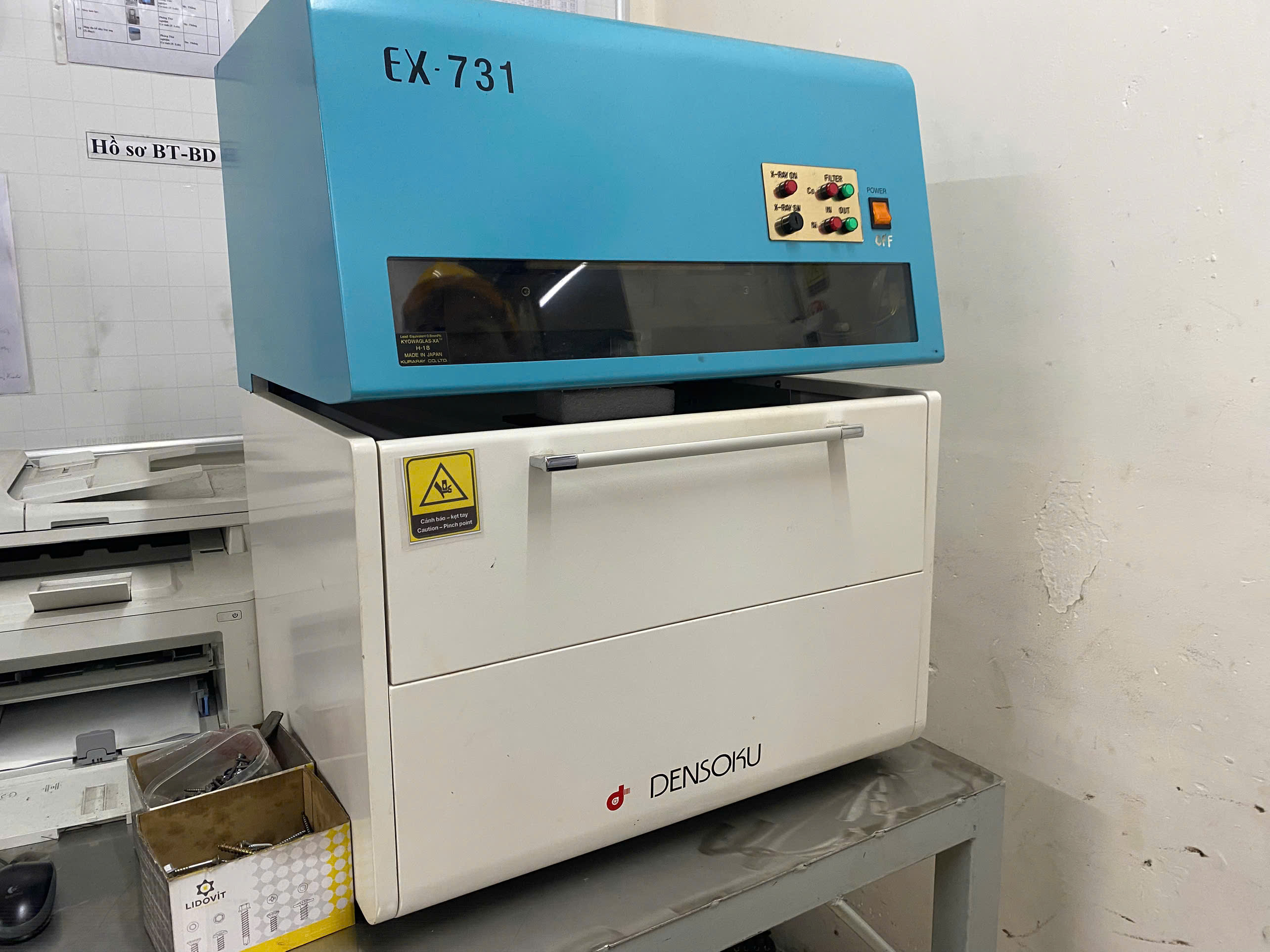
Why Cold Weather Changes Everything
Steel behaves differently in extreme cold. Most carbon and low-alloy steels have a ductile-to-brittle transition temperature (DBTT). Below that point, the metal absorbs far less energy before fracturing. A component that performs well at room temperature can shatter like glass at minus 40°F. This is not theoretical — it is a documented failure mode in renewable energy infrastructure across northern climates.
Thermal expansion and contraction also create cyclic stress. A bracket that goes through daily temperature swings of 60–80°F experiences micro-movements at every bolt hole and weld joint. Over thousands of cycles, this leads to fatigue cracking if the design and material are not appropriate.
The QC Checklist You Should Require
Here is a practical list of quality control checkpoints we implement on projects destined for cold-climate installations:
-
Material certification: Require mill test reports 5 (MTRs) showing chemical composition and mechanical properties for every heat of steel used. Verify carbon equivalent values are within specification.
-
Charpy impact testing: Specify the test temperature at or below the lowest expected service temperature. For most northern U.S. and Canadian projects, we test at minus 40°F. The absorbed energy should meet or exceed the project specification — typically 20 ft-lbs minimum for structural applications.
-
Weld procedure qualification: All welding should follow qualified procedures per AWS D1.1 6 or equivalent. Weld coupons should be tested for tensile strength, bend ductility, and impact toughness at the service temperature.
-
Dimensional inspection: Critical dimensions should be verified using calibrated instruments. For assemblies with tight tolerance stack-ups, we use CMM (coordinate measuring machine) inspection to confirm that mating parts will fit correctly even after thermal contraction.
-
Surface finish verification: Coating thickness should be measured at multiple points per ASTM standards. Any holiday (pinhole) in the coating is a future corrosion initiation site.
-
First Article Inspection Report (FAIR): Before production begins, the first completed part should undergo a full dimensional and functional inspection. This is where most "right first time" problems are caught.
Cold-Weather Material Selection Quick Reference
| Property | Requirement for Sub-Zero Service | How to Verify |
|---|---|---|
| Impact toughness | Charpy V-notch ≥ 20 ft-lbs at service temp | Third-party lab testing per ASTM E23 |
| Carbon equivalent | CE ≤ 0.42 for weldability | Mill test report review |
| Yield strength retention | Must maintain rated strength at min temp | Tensile test at low temperature |
| Coating adhesion | No delamination after thermal cycling | Cross-cut adhesion test per ASTM D3359 |
| Weld quality | No porosity, undercut, or incomplete fusion | Visual + radiographic or ultrasonic inspection |
Our team in Vietnam and China works directly with mills and testing labs to ensure these documents are authentic and traceable. We have seen cases where fabricators provide generic MTRs that do not correspond to the actual material used. This is a red flag. Every MTR should be traceable to a specific heat number, and that heat number should be stamped or etched on the material itself.
When ice accretion is a concern — and it always is for wind turbine components in northern regions — additional load calculations must account for the weight and aerodynamic drag of ice buildup. The QC process should verify that the fabricated components meet the structural margins required for ice-loaded conditions.
How can I collaborate with an engineering team to optimize my part designs for maximum wind load resistance?
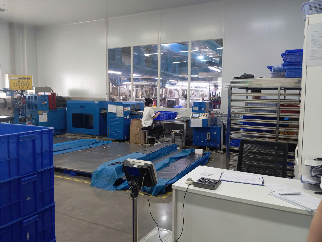
One lesson we learned early in our custom parts business: the best time to optimize a design for wind loads is before the first prototype is cut. We once received drawings from a U.S. client for a large solar tracker mounting plate. The design met all static load requirements, but our engineering team ran a quick finite element analysis 8 and found that the flat, unsupported span would resonate at wind speeds common in the installation region. A simple addition of two stiffening ribs solved the problem at virtually no extra material cost.
Collaborate with your fabricator's engineering team during the design phase by sharing site-specific wind data, requesting finite element analysis on critical components, incorporating stiffening features like ribs and gussets, and using design-for-manufacturability reviews to ensure every bend, hole, and weld joint contributes to wind load resistance without unnecessary cost.
Start With Site-Specific Wind Data
Generic design assumptions lead to either over-engineering (wasted money) or under-engineering (failure). Work with your installation contractor or civil engineer to obtain the design wind speed for the specific project site. In the U.S., ASCE 7 provides wind speed maps and exposure categories. Your fabricator needs this data to calculate the actual forces on each component.
Wind loads are not just about maximum gust speed. They include sustained pressure, oscillating forces, and vortex shedding. Sheet metal components on wind turbines, solar trackers, and outdoor weatherproofing enclosures experience all three. A flat panel catches wind like a sail. A curved or ribbed panel deflects it.
Design Features That Improve Wind Resistance
There are several practical design modifications that improve wind load performance without major cost increases:
-
Stiffening ribs and beads: Pressed or rolled into the sheet metal, these features dramatically increase the moment of inertia of a panel without adding material. Our CNC press brakes can form precise ribs at tolerances of ±0.005 inches.
-
Gussets at corners and joints: Triangular gusset plates at 90-degree joints distribute stress away from weld toes and bolt holes, which are natural stress concentration points.
-
Radiused bends instead of sharp corners: Sharp bends create stress risers. A minimum inside bend radius of 1× material thickness reduces crack initiation under cyclic wind loading.
-
Strategic hole placement: Mounting holes and cutouts should be located away from high-stress zones. Our engineers use FEA to map stress distribution and recommend hole placement that does not compromise fatigue resistance.
-
Aerodynamic shaping: Where possible, tapering or angling exposed edges reduces the frontal area and wind catch. This is especially relevant for equipment housings mounted on towers or poles.
The DFM Review Process
Design for manufacturability (DFM) review is where engineering collaboration pays dividends. Here is how our process works:
- The client shares 3D CAD files and site conditions.
- Our engineering team reviews for manufacturability — can each feature be formed, cut, and welded with available tooling?
- We run structural simulations if the client provides load cases. If not, we work with them to define realistic load scenarios.
- We issue a DFM report with recommended changes, cost impacts, and lead time effects.
- The client approves or modifies, and we proceed to first article production.
This collaborative approach is how we help clients avoid the costly mistake of designing in isolation and then discovering problems during fabrication or — worse — after installation. Custom fabrication tailored to precise functional and environmental requirements consistently outperforms generic off-the-shelf parts, especially for wind loads and NEMA-rated enclosures in exposed locations.
What specific fabrication techniques should I look for to prevent stress cracking in my outdoor energy infrastructure?
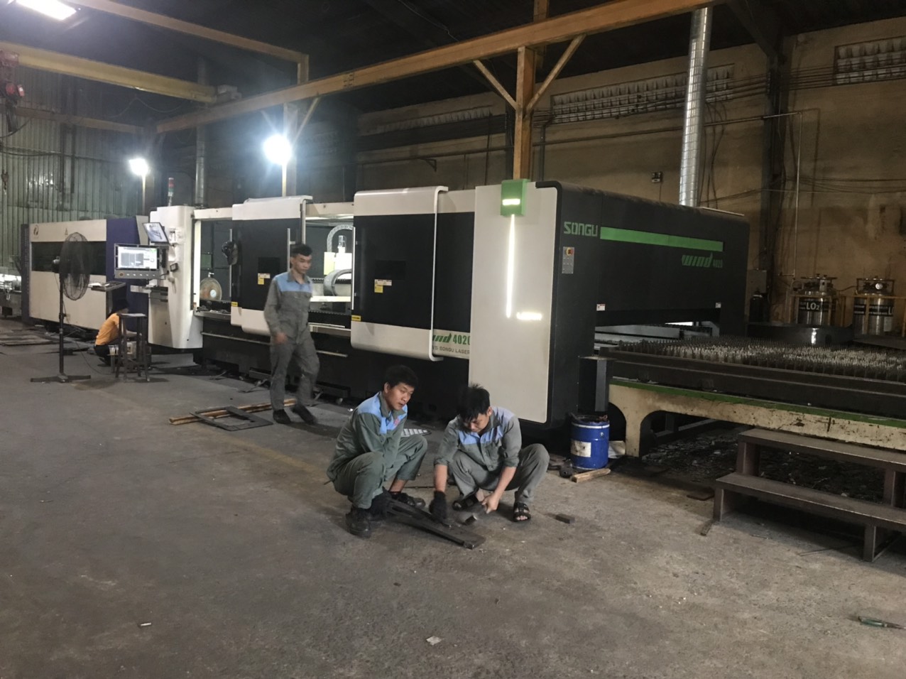
During a recent supplier audit at a factory in Vietnam, we found that a subcontractor was using plasma cutting on 3mm stainless steel brackets intended for a geothermal heat exchanger housing. The heat-affected zone from plasma cutting was introducing residual stress that would almost certainly lead to stress corrosion cracking 9 in the high-temperature, high-moisture service environment. We switched the process to laser cutting 10, which produces a much narrower heat-affected zone, and the problem was resolved before a single part shipped.
To prevent stress cracking in outdoor energy infrastructure, specify laser cutting over plasma for heat-sensitive alloys, require post-weld stress relief on thick sections, use proper bend radii to avoid work-hardening, and ensure continuous weld seams with no gaps that could trap moisture and initiate corrosion-assisted cracking.
What Causes Stress Cracking in Sheet Metal?
Stress cracking in outdoor energy components comes from three interacting factors: residual stress from fabrication, environmental exposure (moisture, temperature, chemicals), and cyclic loading from wind, vibration, or thermal expansion. When all three are present — as they are in nearly every outdoor energy application — the risk is high.
Residual stress is introduced during cutting, bending, welding, and even punching. Every time you deform or heat metal, you change its internal stress state. If those stresses are tensile and align with an aggressive environment, stress corrosion cracking (SCC) can initiate at surprisingly low applied loads.
Fabrication Techniques That Reduce Stress
Not all fabrication methods are equal when it comes to residual stress. Here is a comparison:
| Fabrication Process | Residual Stress Level | Heat-Affected Zone | Best Practice for Energy Projects |
|---|---|---|---|
| Laser Cutting | Low | Very narrow (< 0.5 mm) | Preferred for stainless steel and aluminum |
| Plasma Cutting | Medium-High | Wide (2–4 mm) | Acceptable for carbon steel, avoid for SCC-prone alloys |
| Waterjet Cutting | None | None | Ideal for thick or heat-sensitive materials |
| CNC Punching | Low-Medium | None | Good for hole patterns, avoid near edges |
| TIG Welding | Medium | Moderate | Best for thin gauge and critical joints |
| MIG Welding | Medium-High | Wider | Suitable for thicker sections, requires post-weld treatment |
| Press Brake Bending | Low-Medium | None | Use proper radii to avoid work-hardening |
Post-Fabrication Stress Relief
For critical components — especially those in geothermal systems where high temperatures and wide pressure fluctuations are constant — post-weld stress relief is often necessary. This involves heating the welded assembly to a specific temperature (typically 1100–1200°F for carbon steel) and holding it for a calculated period, then cooling slowly. This process relaxes residual tensile stresses and reduces the risk of SCC.
For stainless steel, solution annealing may be required after welding to restore corrosion resistance in the heat-affected zone. Without this step, sensitization can occur — chromium carbides form at grain boundaries, depleting the chromium that provides corrosion resistance. This is a well-known failure mechanism in 304 stainless steel exposed to temperatures between 800°F and 1500°F during welding.
Welding Best Practices for Outdoor Energy Components
Welding is recognized as the most effective assembly technique for achieving weather resistance because it creates continuous, sealed joints. But the weld itself must be executed correctly:
- Use low-hydrogen electrodes or shielding gas to prevent hydrogen embrittlement.
- Ensure full penetration on structural joints — partial penetration welds are stress concentration points.
- Grind weld toes to a smooth profile to reduce stress concentration factors.
- Apply continuous sealant where welds meet overlapping joints to prevent moisture ingress.
- Inspect all welds visually and, for critical joints, with dye penetrant or ultrasonic testing.
Geothermal systems demand high-strength metal fabrication engineered to perform reliably under extreme conditions. Wind turbine components require extraordinary strength, precision, and corrosion resistance. In both cases, the fabrication technique is as important as the material itself. Renewable energy systems installed outdoors face corrosion, moisture, and temperature fluctuations that test every weld and every bend over decades of service. Understanding what factors affect the service life of sheet metal fabrication products is essential when selecting the right processes for these demanding applications.
Our process control approach includes welding procedure qualification records (WPQRs), welder performance qualifications, and in-process inspection at defined intervals. This is how we deliver the "right first time" results that our U.S. clients require — because rework on a stress-cracked part installed on a remote wind farm is not just expensive, it is often impossible.
Conclusion
Ensuring sheet metal fabrication for energy projects withstands extreme weather requires deliberate choices at every stage — from alloy and coating selection through precision quality control, wind-optimized design, and stress-conscious fabrication techniques. The decisions you make with your fabricator early in the design phase determine whether your components last five years or twenty-five. Engage an experienced partner who understands anti-corrosion requirements for energy infrastructure sheet metal fabrication and insists on getting it right the first time.
Frequently Asked Questions
What Causes Stress Cracking in Sheet Metal?
Stress cracking in outdoor energy components comes from three interacting factors: residual stress from fabrication, environmental exposure (moisture, temperature, chemicals), and cyclic loading from wind, vibration, or thermal expansion. When all three are present — as they are in nearly every outdoor energy application — the risk is high.
How do I choose the right alloy and coating to protect my sheet metal components from salt spray and high humidity?
A buyer we work with in the Gulf Coast region once asked us to quote two versions of the same solar panel mounting bracket — one in standard carbon steel and one in 316L stainless 2 . The price difference was significant. But when we ran a total cost of ownership analysis over the expected 25-year service life, the stainless option was actually cheaper because it eliminated two full coating replacement cycles and avoided structural failure risk.
What quality control standards should I demand from my supplier to guarantee performance in sub-zero temperatures?
Last winter, one of our clients shipping to a wind farm project in Minnesota discovered that a competitor's brackets had fractured during installation. The temperature was minus 25°F. The root cause was a combination of high-carbon steel and no impact testing — the material underwent a ductile-to-brittle transition well above the operating temperature. That scenario is exactly what proper QC prevents.
Footnotes
1. Replaced with a working Wikipedia page on metal fabrication, which encompasses sheet metal fabrication. ↩︎
2. Details the properties, fabrication, and applications of 316L stainless steel. ↩︎
3. Explains the process and benefits of hot-dip galvanizing for corrosion protection. ↩︎
4. Replaced with a working Wikipedia page for Powder Coating, as the original domain’s page returned a 403 error. ↩︎
5. Replaced with a working Wikipedia page for Mill Test Report. ↩︎
6. Links to the American Welding Society’s structural welding code for steel. ↩︎
7. Replaced with a working Wikipedia page for Charpy impact test, which includes V-notch testing. ↩︎
8. Replaced with a working Wikipedia page for Finite Element Method, which is the underlying method for finite element analysis. ↩︎
9. Explains the mechanism and factors contributing to stress corrosion cracking. ↩︎
10. Replaced with a working Wikipedia page for Laser Cutting. ↩︎