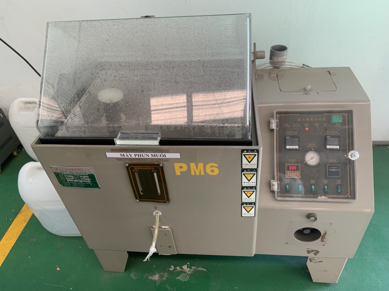
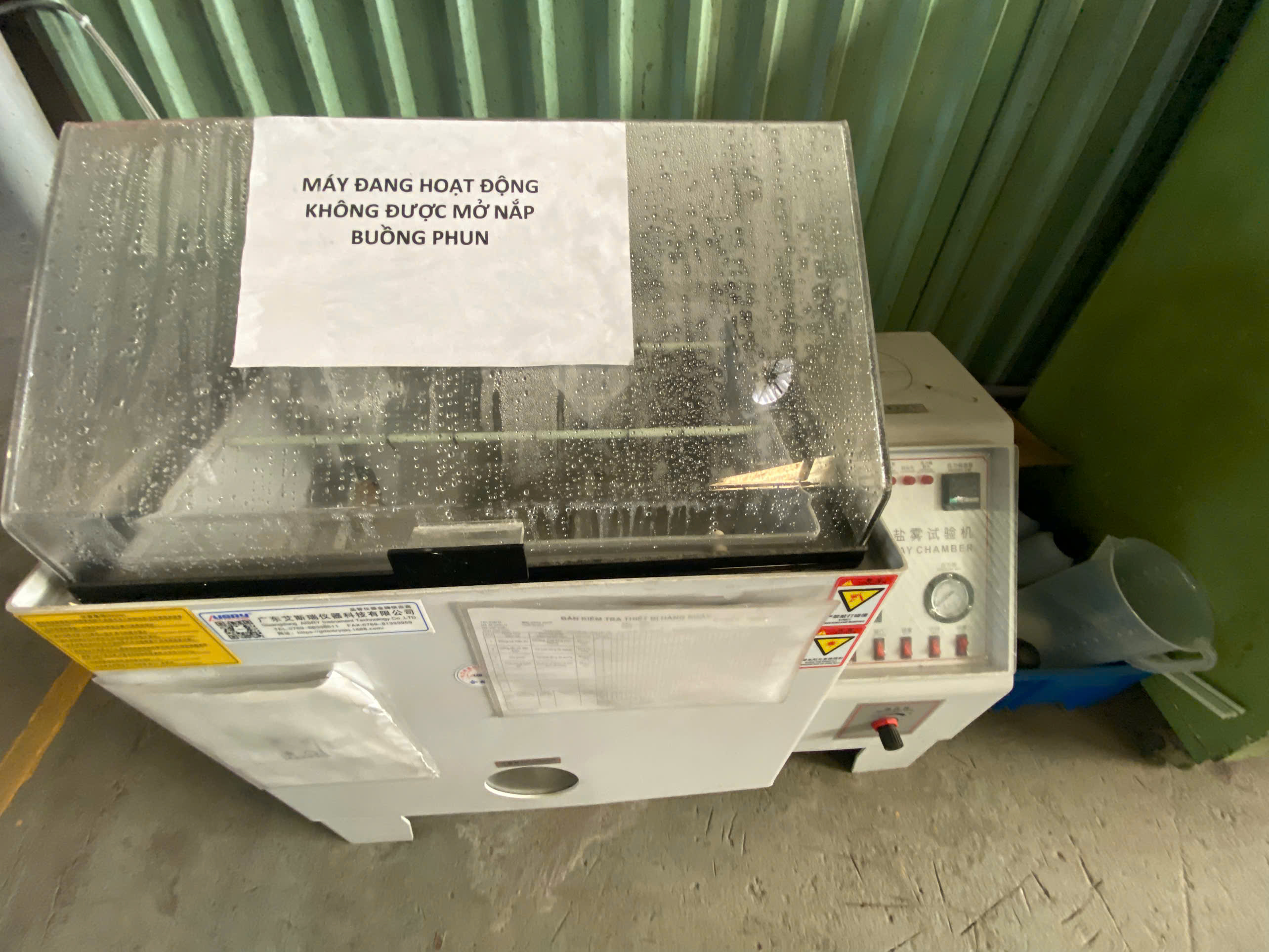
When a shipment of custom stamping parts fails salt spray corrosion resistance tests at the buyer’s facility, the fallout is brutal — rejected lots, costly rework, and damaged trust that takes months to rebuild.
Ensuring stamping parts pass salt spray corrosion resistance tests requires a system-level approach: specifying the correct base metal composition, applying properly thick coatings with edge protection, aligning on the exact test standard and acceptance criteria before production, and verifying supplier QC at every step from surface pre-treatment through final inspection.
This guide breaks down the entire process — from choosing coatings and materials to auditing suppliers and specifying test standards — so you can lock in corrosion performance before a single part ships.
How can I choose the right coating or plating to meet salt spray test requirements?
A buyer once asked our team to quote a steel mounting bracket that needed 500 hours of neutral salt spray performance, but the drawing said nothing about coating type, thickness, or whether cut edges were included in the acceptance criteria — a recipe for failure.
To meet salt spray test requirements, choose a coating system matched to your target hours and environment: zinc plating with chromate conversion coating for 96–200 hours, zinc-nickel alloy for 500–1,000 hours, or powder coating over phosphate pre-treatment for 1,000+ hours, always specifying minimum thickness on critical surfaces.
Matching Coating Systems to Hour Targets
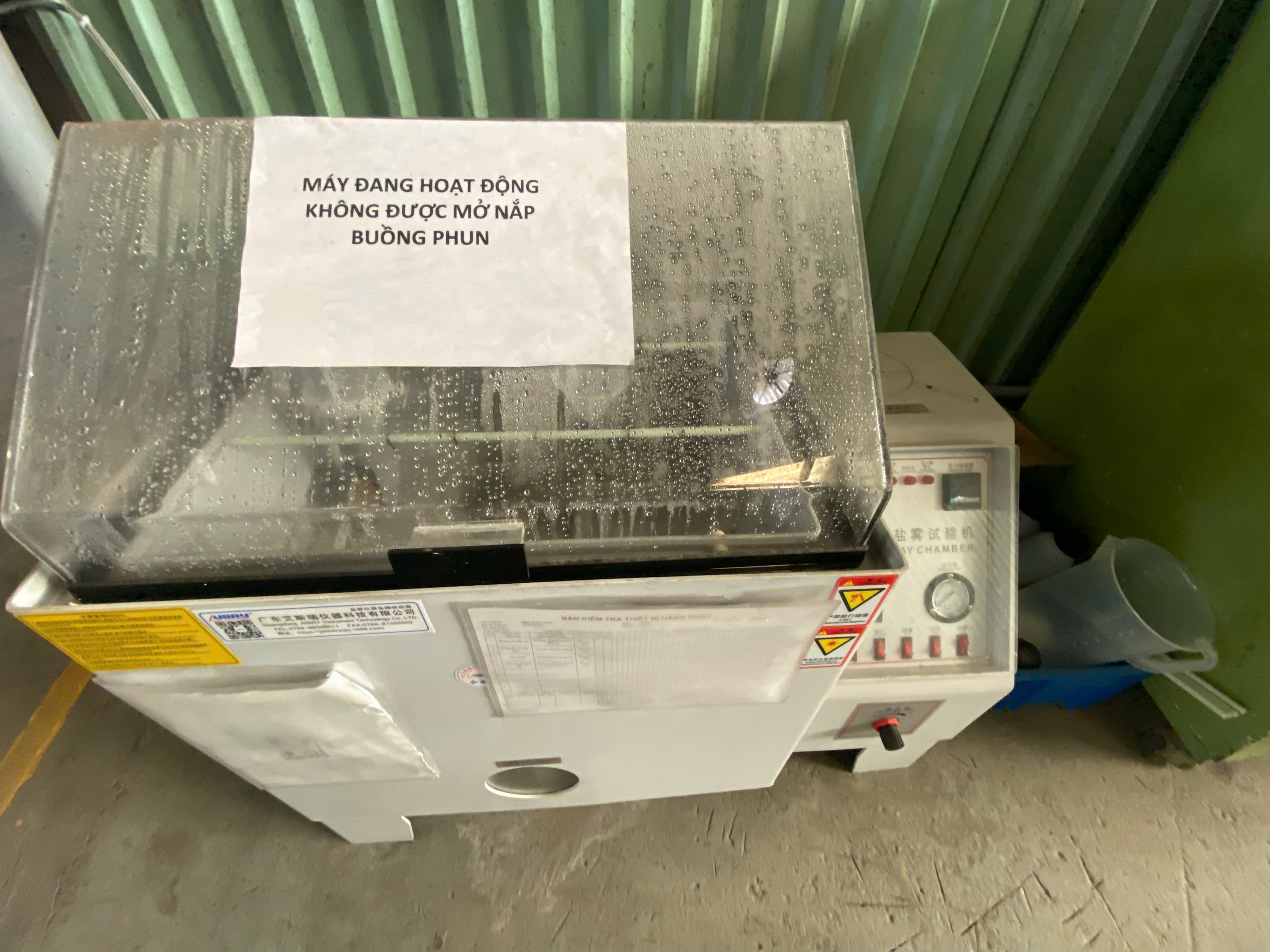
The first step is understanding what "hours" actually mean. Salt spray hours under the ASTM B117 standard 1 measure comparative resistance, not real-world lifespan. But they remain the universal language between buyers and suppliers. Here is a practical reference we share with clients during co-development:
| Coating System | Typical Salt Spray Hours (to Red Rust) | Best For | Key Consideration |
|---|---|---|---|
| Zinc plating (clear chromate) | 72–120 hours | Indoor hardware, low-cost brackets | Zinc plating thickness must be ≥8 µm minimum |
| Zinc plating (trivalent chromate) | 120–240 hours | General industrial brackets | Chromate conversion coating quality is critical |
| Zinc-Nickel alloy (12–15% Ni) | 500–1,000 hours | Automotive, outdoor structural | Higher cost, requires specialized plating lines |
| Hot-dip galvanizing | 300–600 hours | Large structural parts, post bases | Thick coating; may affect hole tolerances |
| Powder coating over phosphate | 500–1,500+ hours | Exterior brackets, furniture hardware | Powder coating durability depends on pre-treatment |
| E-coat + powder topcoat | 1,000+ hours | Automotive underbody, trailer hitches | Multi-layer system; highest cost and performance |
Why Thickness Matters More Than Coating Type
I have seen zinc-plated parts from two different suppliers — same chemistry, same standard — and one passes 200 hours while the other fails at 80. The difference? Zinc plating thickness. On flat surfaces, the plating may reach 12 µm, but in recessed areas or near stamped holes, it can drop to 3–4 µm. This is the "low-current density" problem in electroplating 2. When we audit plating suppliers, we check thickness at the worst-case locations, not just the flat faces.
The Edge Sealing Decision
Stamped parts have cut edges where bare base metal is exposed. No electroplating process can build adequate thickness on a sharp sheared edge. You have three options: deburr the edges to a radius so the coating wraps better, apply a secondary sealant or wax after plating, or accept that edges will show earlier corrosion and exclude them from acceptance criteria. Our recommendation is to specify this upfront in the RFQ. Ambiguity here is the number-one cause of disputes after testing.
Nanotechnology Sealers and Advanced Options
For high-performance applications, nano-sealers can fill sub-microscopic pores in the primary plating layer. We have evaluated these on zinc-nickel parts 3 destined for U.S. automotive aftermarket customers. The results showed a measurable improvement — parts that previously reached 720 hours to white rust extended past 900 hours. The trade-off is cost and process complexity; not every plating house can apply them consistently.
What design and material factors should I consider to improve corrosion resistance in stamping parts?
During a recent project for a U.S. distributor, we discovered that a trailer-hitch mounting bracket kept failing salt spray at the bend radius — not the flat surface, not the edge, but the exact point where residual stress from stamping met thin coating coverage.
To improve corrosion resistance, select a base metal with inherent corrosion tolerance, minimize sharp edges and deep draws that thin coatings, deburr all cut edges, relieve residual stamping stresses through thermal treatment, and eliminate pooling zones in the part geometry where salt solution can accumulate during testing or service.

Base Metal Selection
The base metal composition sets the floor for corrosion performance. Not all carbon steels are equal. A steel with higher copper or chromium content resists red rust formation longer than a plain low-carbon grade, even before coating. For stainless steel stampings, the grade matters enormously — 304 stainless 4 handles most environments, but 316 is essential for coastal or chemical exposure. If you are stamping from pre-coated material like galvanized steel, the zinc layer thickness on the incoming coil directly affects the final part's performance.
| Design / Material Factor | Impact on Salt Spray Performance | Recommended Action |
|---|---|---|
| Sharp stamped edges | Coating thins at edges; first corrosion site | Deburr to ≥0.3 mm radius |
| Deep draws / tight bends | Coating stretches and cracks | Design bend radii ≥2× material thickness |
| Residual stress from forming | Accelerates stress-corrosion cracking 5 | Thermal stress relief at 200–300°C |
| Weld seams | Heat-affected zone alters microstructure | Post-weld passivation treatment |
| Pooling zones (cups, channels) | Salt solution accumulates, intensifying attack | Add drain holes or orient part to shed liquid |
| Iron contamination on stainless | Free iron particles initiate pitting | Chemical passivation with citric or nitric acid |
The Cut Edge Problem — In Detail
When a stamping die shears through coated sheet metal, it exposes raw steel along the entire cut perimeter. On a bracket with 20 mounting holes, that is a significant length of unprotected edge. Our engineering team flags this during DFM review. We mark every cut edge on the drawing and ask the buyer: "Do you need red rust protection here, or is this edge hidden in the assembly?"
If protection is required, the options include post-plating the stamped part (which adds the full coating system to the edges), applying edge sealant or wax, or switching to a post-coat stamping sequence where the part is coated after all cutting operations are complete.
Simulation-Driven Design
For complex stamped assemblies — like the L-brackets and post bases in our product range — we use simulation to identify where salt solution will pool during a test. A flat base plate with a welded vertical channel can trap moisture in the inside corner. That trapped solution accelerates corrosion far beyond what flat coupons experience. Adding a small drain notch or repositioning a mounting hole can eliminate the problem at zero cost.
Stress Relief for High-Strength Parts
High-strength stamped parts carry significant residual internal stresses from the forming process. These stresses can cause stress-corrosion cracking, where the part fails not just from surface corrosion but from cracks propagating inward. Thermal stress relief — typically a low-temperature bake at 200–300°C for one to two hours — reduces this risk significantly. We include this step in the process control plan for any part with a hardness above HRC 35.
How do I verify a supplier's QC process ensures consistent salt spray test results?
One lesson we learned early in our supply chain management 6 work: a supplier can send you a beautiful salt spray test report showing 720 hours to red rust — but the tested coupon was a flat panel, not your actual stamped part with all its holes, bends, and welds.
To verify consistent salt spray results, require that test specimens are actual production parts (not flat coupons), demand process control records for coating thickness, surface pre-treatment, and cure parameters, conduct periodic third-party lab testing, and audit the supplier's chamber calibration and sample preparation procedures on-site.

The "Sample Match" Problem
This is the single biggest gap we encounter. A supplier's in-house test report may be legitimate — but it tests a flat coupon processed alongside your parts, not the parts themselves. A flat coupon has no edges, no bends, no recessed areas. It will always outperform the real part. When we manage supplier quality for our U.S. clients, we require that the tested sample is the actual part, identified by part number, production date, and batch.
Five Documents You Should Request
Rather than relying on a single pass/fail report, build a documentation package that traces the entire process:
- Coating thickness inspection report — with measurements at multiple locations on the actual part, including edges and recesses, using a calibrated gauge.
- Surface pre-treatment records — chemical concentrations, bath temperatures, and dwell times for cleaning, acid activation, and phosphating or passivation.
- Cure/bake records — oven temperature profiles and duration for powder coating or post-plating bakes.
- Salt spray test report — specifying the standard used, duration, number of samples, and photographs at defined intervals.
- Chamber calibration certificate — proving the test chamber meets ASTM B117 or ISO 9227 requirements for temperature, fog collection rate, and solution concentration.
Red Flags in Supplier Data
Through years of auditing plating and coating suppliers across Asia, our team has developed a checklist of warning signs:
- Test report shows only "pass" with no photographs or hourly observations.
- Tested specimen description is vague (e.g., "steel panel" instead of your part number).
- No coating thickness data at edge or low-current locations.
- Chamber calibration certificate is expired or from an unaccredited lab.
- Supplier cannot explain their electroplating quality control parameters when asked.
Building Ongoing Consistency
A single passing test proves the supplier can meet the requirement. It does not prove they will meet it on every batch. Our approach is to include salt spray testing in the PPAP (Production Part Approval Process) 7 and then require periodic re-testing — typically every 10th or 20th production batch, or whenever the supplier changes a chemical bath, a pre-treatment step, or a raw material source. You can learn more about how to request batch salt spray testing from sheet metal fabrication suppliers to formalize this process.
We also recommend that buyers conduct independent verification through a third-party lab at least once per year. Ship production samples directly from the warehouse to an accredited lab. Do not rely solely on supplier-submitted samples.
What salt spray test standards and hour ratings should I specify for my custom stamping parts?
When our team helps U.S. clients draft specifications for custom brackets and mounting hardware, the question of "how many hours" always comes up early — but it is actually the wrong first question. The right first question is: which standard, which test variant, and what counts as failure?
Specify ASTM B117 for neutral salt spray (NSS) as the baseline standard, define the test variant (NSS, AASS, or CASS), set hour targets based on your end-use environment (96–240 hours for indoor, 500–1,000+ hours for automotive or outdoor), and clearly state whether failure means white rust, red rust, blistering, or scribe creep.
Understanding the Three Test Variants
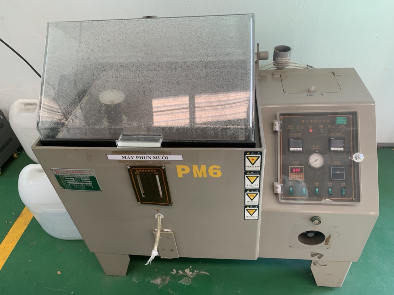
The ISO 9227 standard 8 defines three distinct test types. Each uses different chemistry and targets different coating systems. Choosing the wrong variant gives meaningless data.
| Test Variant | Solution Chemistry | Temperature | Primary Application |
|---|---|---|---|
| NSS (Neutral Salt Spray) | 5% NaCl, pH 6.5–7.2 | 35°C ± 2°C | General corrosion testing for zinc, cadmium, and organic coatings |
| AASS (Acetic Acid Salt Spray) | 5% NaCl + acetic acid, pH 3.1–3.3 | 35°C ± 2°C | Anodized aluminum, decorative copper-nickel-chromium |
| CASS (Copper-Accelerated Acetic Acid) | 5% NaCl + acetic acid + CuCl₂, pH 3.1–3.3 | 50°C ± 2°C | Decorative chrome plating, high-performance automotive finishes |
For most stamped steel brackets and hardware, NSS per ASTM B117 is the correct choice. CASS is reserved for decorative chrome finishes on parts like automotive trim. Using CASS on a zinc-plated bracket would be unnecessarily aggressive and lead to misleading failures.
Setting Hour Targets by Application
Hour ratings should reflect the end-use environment, not arbitrary round numbers. Here is a guide we use internally:
| Application | Recommended NSS Hours (to Red Rust) | Notes |
|---|---|---|
| Indoor furniture hardware | 48–96 hours | Minimal moisture exposure |
| General industrial brackets | 96–240 hours | Warehouse, factory environments |
| Outdoor structural mounts | 240–500 hours | Rain, humidity, but not salt-heavy |
| Automotive underbody / coastal | 500–1,000 hours | Road salt, sea spray |
| Marine or defense | 1,000+ hours | Continuous salt exposure |
Defining What "Failure" Means
This is where most specifications fall short. "Pass 500 hours" is incomplete. You need to state: 500 hours to what? White corrosion (zinc oxide) is cosmetically unappealing but functionally harmless — the zinc layer is sacrificially protecting the steel underneath. Red rust means the steel base is corroding. Blistering means the coating has lost adhesion. Scribe creep (measured per ASTM D1654 9) evaluates how far corrosion migrates from a deliberate scratch.
Our standard recommendation is to specify both: "No red rust formation on primary surfaces after X hours NSS per ASTM B117. White corrosion on cut edges is acceptable / not acceptable."
The Shift Toward Cyclic Testing
The industry is moving beyond salt spray hours as a standalone metric. Cyclic corrosion testing 10 (CCT) alternates between salt spray, humidity, and dry phases to simulate real-world conditions more accurately. While ASTM B117 remains the standard for supplier qualification and incoming inspection, forward-thinking buyers are supplementing it with cyclic tests for critical applications. For a deeper understanding of how salt spray testing evaluates corrosion resistance in sheet metal fabrication, it helps to review the mechanics of the test itself. We advise clients to start with ASTM B117 for baseline qualification and add CCT requirements when the application demands higher confidence.
Proper Chamber Setup for Accurate Results
Even a perfect coating will fail if the test is run incorrectly. Key parameters: specimens must be oriented at 15 to 30 degrees from vertical so fog settles evenly without pooling. The saline solution uses 5% NaCl with salt purity above 95%, mixed in deionized water with conductivity below 20 µS/cm. The chamber holds at 35°C ± 2°C. Solution in the reservoir must be refreshed every 48 hours. Samples must be handled with gloves — a single fingerprint can create a localized corrosion site that skews results.
After removal, parts should be rinsed with running water, dried with compressed air at about 40 psi, and inspected immediately. Delays allow salt deposits to dry and obscure the actual corrosion state.
Conclusion
Passing salt spray corrosion resistance tests on stamping parts demands a system-level approach — from RFQ precision through coating selection, design optimization, supplier verification, and standard alignment — not a single last-minute fix. Beyond testing, understanding rust prevention and storage for stamping parts is equally important to maintain corrosion performance after production.
Frequently Asked Questions
How can I choose the right coating or plating to meet salt spray test requirements?
A buyer once asked our team to quote a steel mounting bracket that needed 500 hours of neutral salt spray performance, but the drawing said nothing about coating type, thickness, or whether cut edges were included in the acceptance criteria — a recipe for failure.
What design and material factors should I consider to improve corrosion resistance in stamping parts?
During a recent project for a U.S. distributor, we discovered that a trailer-hitch mounting bracket kept failing salt spray at the bend radius — not the flat surface, not the edge, but the exact point where residual stress from stamping met thin coating coverage.
How do I verify a supplier's QC process ensures consistent salt spray test results?
One lesson we learned early in our supply chain management 6 work: a supplier can send you a beautiful salt spray test report showing 720 hours to red rust — but the tested coupon was a flat panel, not your actual stamped part with all its holes, bends, and welds.
Footnotes
1. Official standard defining neutral salt spray test methodology referenced throughout article. ↩︎
2. Surface finishing industry authority relevant to electroplating thickness issues described. ↩︎
3. Authoritative Wikipedia section explaining zinc-nickel plating properties and corrosion resistance. ↩︎
4. Background on the common stainless steel grade mentioned for corrosion resistance. ↩︎
5. Explains the failure mechanism caused by residual stamping stresses discussed in article. ↩︎
6. Background concept for the broader supplier verification practices described in article. ↩︎
7. AIAG governs the PPAP standard referenced for supplier qualification process. ↩︎
8. International standard defining the three salt spray test variants discussed in article. ↩︎
9. Official standard for evaluating scribe creep corrosion migration mentioned in article. ↩︎
10. Corrosion industry association provides authority on advanced cyclic testing methods. ↩︎