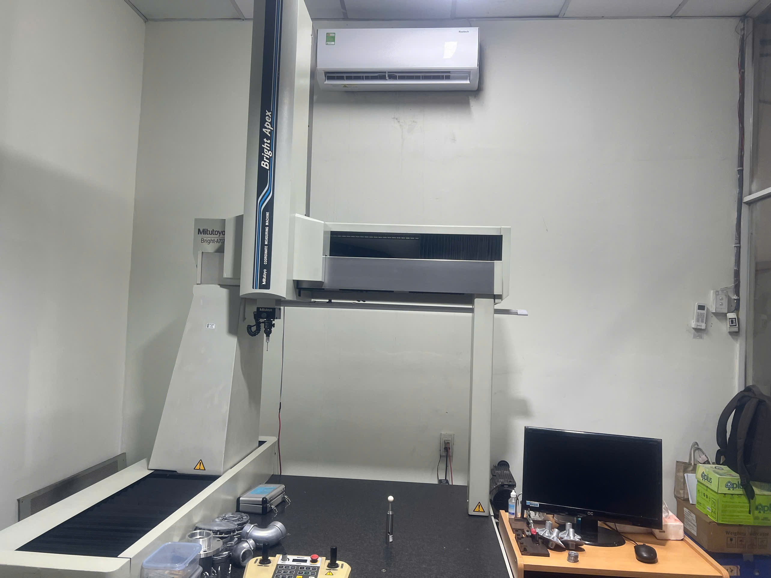

Evaluating quality inspection equipment and CMMs 1 can determine whether your sheet metal project succeeds or fails on the first run.
To evaluate quality inspection equipment and CMMs when sourcing sheet metal fabrication, verify dimensional accuracy capabilities, calibration records, equipment range, operator expertise, and integration with your quality control plan. Prioritize suppliers whose inspection systems match your tightest tolerances and most complex geometries.
I have spent years helping U.S. purchasing managers source custom sheet metal parts from factories across Asia. One lesson keeps repeating itself: a supplier can own the best laser cutters 2 and press brakes in the world, but if their inspection equipment cannot catch a 0.05mm deviation, you will receive parts that do not fit. This article walks through exactly what to look for, how to verify it, and why it matters for your bottom line.
What specific inspection equipment should I look for to ensure my sheet metal parts meet tight tolerances?
A client once sent back an entire shipment of mounting brackets because hole positions drifted by 0.3mm. The supplier had checked parts with a tape measure. That experience taught our team to audit inspection equipment before approving any factory for precision work.
Look for Coordinate Measuring Machines (CMMs) with 5-micron accuracy, laser scanners for full-field dimensional comparison, optical profilometers for surface finish inspection, hardness testers, and non-destructive testing (NDT) tools like ultrasonic and eddy current systems to cover all critical quality dimensions.

Core Inspection Equipment Categories
Not every piece of inspection equipment serves the same purpose. Sheet metal parts require checks across multiple quality dimensions: dimensional accuracy, surface integrity, mechanical strength, and internal soundness. Here is a breakdown of the equipment categories you should look for when evaluating a supplier's quality control capabilities.
| Equipment Type | What It Measures | Typical Accuracy | Best For |
|---|---|---|---|
| CMM (Contact Probe) | 3D geometry, hole positions, angles | ±0.005mm (5 microns) | Complex formed parts with tight GD&T |
| Laser Scanner | Full-surface deviation from CAD | ±0.01–0.05mm | Flatness, warpage, overall shape |
| Optical Profilometer | Surface roughness (Ra, Rz) | Sub-micron | Surface finish inspection after coating |
| Ultrasonic Tester (NDT) | Internal laminations, wall thickness | ±0.01mm thickness | Thick plate, welded assemblies |
| Universal Testing Machine (UTM) | Tensile strength, elongation | ±0.5% of reading | Verifying material properties |
| Hardness Tester | Rockwell, Vickers, Brinell hardness | ±1 HRC | Heat-treated or hardened parts |
| Height Gauge / Calipers | Linear dimensions | ±0.01–0.02mm | Quick in-process checks |
Why Basic Tools Are Not Enough
Calipers and micrometers are essential for quick checks on the shop floor. But they cannot measure the geometric dimensioning and tolerancing 3 (GD&T) callouts that appear on most engineering drawings for precision brackets and housings. When our Vietnam office audits a factory, we check whether they rely solely on hand tools or also maintain programmable CMMs and optical metrology systems. A factory that only owns calipers is not equipped for parts with positional tolerances of ±0.1mm or tighter. For a deeper look at which tools serve which purpose, see our guide on what measuring tools are used for sheet metal dimensional inspection.
Matching Equipment to Your Part Complexity
Simple flat parts with a few holes may only need a height gauge and a go/no-go pin gauge. But the moment your part has multiple bends, welded tabs, and critical mounting holes—like the mirrored mounting brackets shown in our product range—you need a CMM or a laser scanner to verify the full 3D geometry against CAD. The key is to match the inspection capability to your part's complexity. Over-investing in inspection for simple parts wastes money. Under-investing for complex parts causes field failures.
How can I verify that a supplier's CMM is properly calibrated for my custom project?
During a recent factory audit in Vietnam, I asked to see the CMM calibration certificate. The factory manager pointed to a sticker on the machine dated three years ago. That single observation saved our client from committing to a supplier whose measurement data could not be trusted.
Verify CMM calibration by requesting the most recent calibration certificate from an accredited lab, confirming annual calibration intervals, checking measurement uncertainty values, running a test measurement on a known artifact, and ensuring the environment meets temperature and vibration requirements for accurate readings.
What a Valid Calibration Certificate Should Show
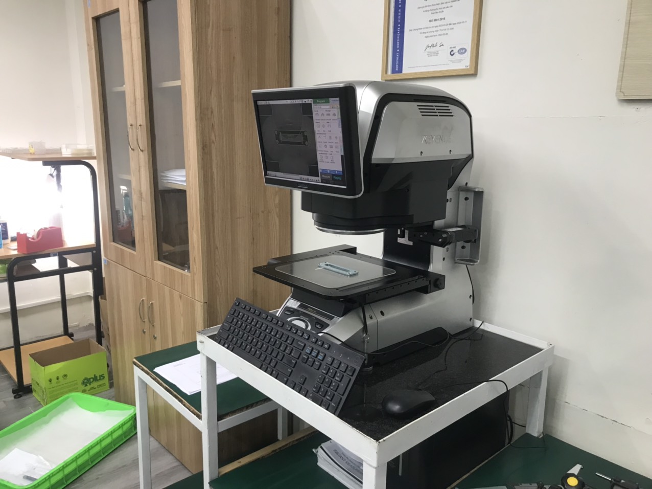
A proper calibration certificate is more than a sticker on the machine. It should come from an ISO 17025 accredited laboratory 4. It should list the date of calibration, the measurement uncertainty 5 at each axis, the reference standards used, and the next due date. When our team reviews these documents, we look for specific details that confirm the CMM can still perform within its stated accuracy range.
| Calibration Document Element | What to Look For | Red Flag |
|---|---|---|
| Issuing lab accreditation | ISO 17025 accredited | No accreditation listed |
| Calibration date | Within the last 12 months | Older than 12 months |
| Measurement uncertainty | Stated in microns per axis | Uncertainty not declared |
| Reference standards | Traceable to national standard | No traceability info |
| Environmental conditions | Temperature 20°C ±1°C recorded | No environment data |
| Next calibration due date | Clearly stated | Missing or overdue |
Environmental Factors That Affect CMM Accuracy
A CMM sitting in a temperature-controlled quality lab will perform very differently from one placed next to a welding station on the factory floor. Temperature fluctuations cause thermal expansion in both the CMM structure and the parts being measured. Floor vibrations from nearby presses or forklifts can introduce measurement errors. When we conduct supplier audits, we check the physical location of the CMM. If the room lacks climate control or sits on a shared production floor, we flag it. Measurement uncertainty increases significantly in uncontrolled environments.
Running a Test Measurement
The most practical way to verify calibration is to bring a known artifact—a gauge block or a calibrated ring gauge—and ask the operator to measure it on the CMM. Compare the reported value to the certified value of the artifact. If the difference exceeds the CMM's stated accuracy, the machine needs recalibration. This takes about 15 minutes during an audit and gives you real confidence in the equipment calibration status. We have found this step catches issues that paper certificates sometimes miss, especially if a CMM has been bumped or relocated since its last formal calibration.
D.C.C. Programming and Repeatability
Modern CMMs with Direct Computer Control 6 allow operators to program measurement routines that run automatically. This means every part is measured the same way, eliminating operator-dependent variation. When evaluating a supplier, ask whether they use programmed routines or manual probing. Programmed routines produce repeatable results and can be tied directly to your CAD model for automated comparison. Manual probing is slower, less repeatable, and more prone to human error. For custom projects with ongoing production, D.C.C. capability is a must.
Why is a CMM essential for the quality control of my complex sheet metal assemblies?
One trade-off we frequently discuss with clients involves cost versus risk. Skipping CMM verification on a $2 bracket seems reasonable. But when that bracket holds a sensor inside a $50,000 machine, a 0.2mm positional error becomes a $50,000 problem.
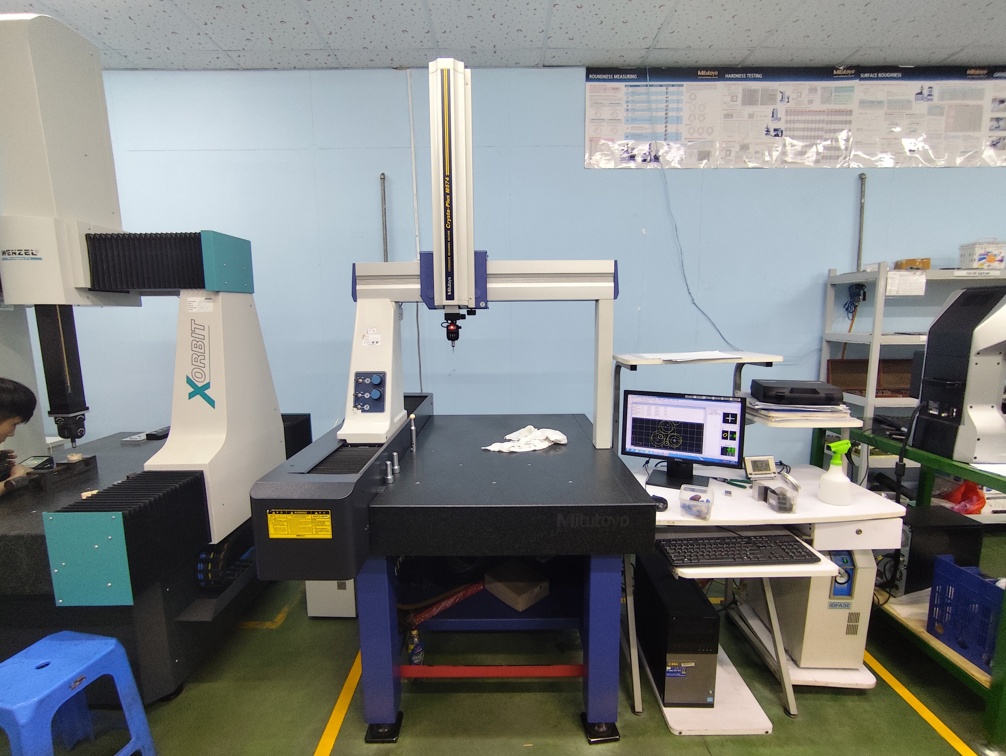
A CMM is essential for complex sheet metal assemblies because it provides high-precision 3D measurement of formed geometries, verifies true position of mounting holes, confirms angular relationships between bends, and generates digital inspection reports that document conformance to geometric dimensioning and tolerancing (GD&T) requirements.
What Makes Sheet Metal Assemblies Complex
Complexity in sheet metal assemblies comes from multiple sources: compound bends that create 3D shapes, welded joints between sub-components, tight positional tolerances on mounting holes, and critical interfacing surfaces. The mirrored mounting brackets we produce, for example, feature angular folds, irregular cutouts, multiple drilled holes across different planes, and weld joints. Verifying that all these features are within tolerance requires measuring in three dimensions simultaneously. No hand tool can do this efficiently.
CMM vs. Laser Scanning for Assembly Verification
Both CMMs and laser scanners serve the goal of 3D measurement, but they work differently and have distinct advantages. Here is a comparison relevant to sheet metal assemblies:
| Criteria | CMM (Contact Probe) | Laser Scanner (Non-Contact) |
|---|---|---|
| Accuracy on holes and positions | Excellent (±0.005mm) | Good (±0.01–0.05mm) |
| Speed | Slow (point-by-point) | Fast (thousands of points per second) |
| Surface coverage | Discrete points only | Full-surface scan |
| Edge feature accuracy | Limited—struggles with kerf edges | Better for overall profiles |
| Flatness and warpage | Good with enough points | Excellent with full-field data |
| Operator skill required | High (programming needed) | Medium (newer systems are single-click) |
| Environmental sensitivity | High (needs controlled room) | Lower (portable systems available) |
| Cost | High | Medium to high |
For our projects, we often recommend a combined approach. The CMM verifies critical hole positions and GD&T callouts. A laser scanner checks overall shape, flatness, and warpage across the full surface. This dual strategy catches both localized and global dimensional issues.
How CMM Data Supports Your Quality Control Plan
Every custom project should have a documented quality control plan. The CMM plays a central role in this plan by providing traceable measurement data for first article inspection 7 (FAI), ongoing production checks, and final inspection. When we manage production for U.S. clients, we use CMM reports as part of our PPAP documentation 8. These reports show exactly which dimensions were measured, the actual values, and whether they fall within tolerance. This data becomes evidence that the supplier delivered conforming parts—and it protects both the buyer and the supplier if a dispute arises. For a detailed look at key quality inspection steps for finished sheet metal products, we have a separate guide covering the full process.
The Limitations You Should Know
CMMs are not perfect. They are slow compared to automated inspection systems. They struggle with edge-defined features because the probe stylus can slip off sharp edges, sometimes producing measurements less accurate than a simple caliper. They are sensitive to floor vibrations and temperature changes. And they require skilled operators to program and run effectively. Understanding these limitations helps you set realistic expectations. For some features—like a laser-cut edge profile—optical metrology or a laser scanner may actually give you better data than a CMM.
How do I evaluate if a factory's QC team has the expertise to interpret my technical drawings correctly?
Last year, a supplier missed a critical flatness callout on a housing base. The symbol was right there on the drawing. The QC inspector simply did not know what it meant. That single oversight caused three weeks of delay and a full batch of rework. It reminded our team that equipment means nothing without the people who operate it.
Evaluate a factory's QC team by reviewing their understanding of GD&T symbols, asking them to walk through your drawing and identify critical dimensions, checking their inspection planning process, verifying their experience with similar parts, and confirming they have formal training or certifications in metrology and quality systems.
The Drawing Walkthrough Test
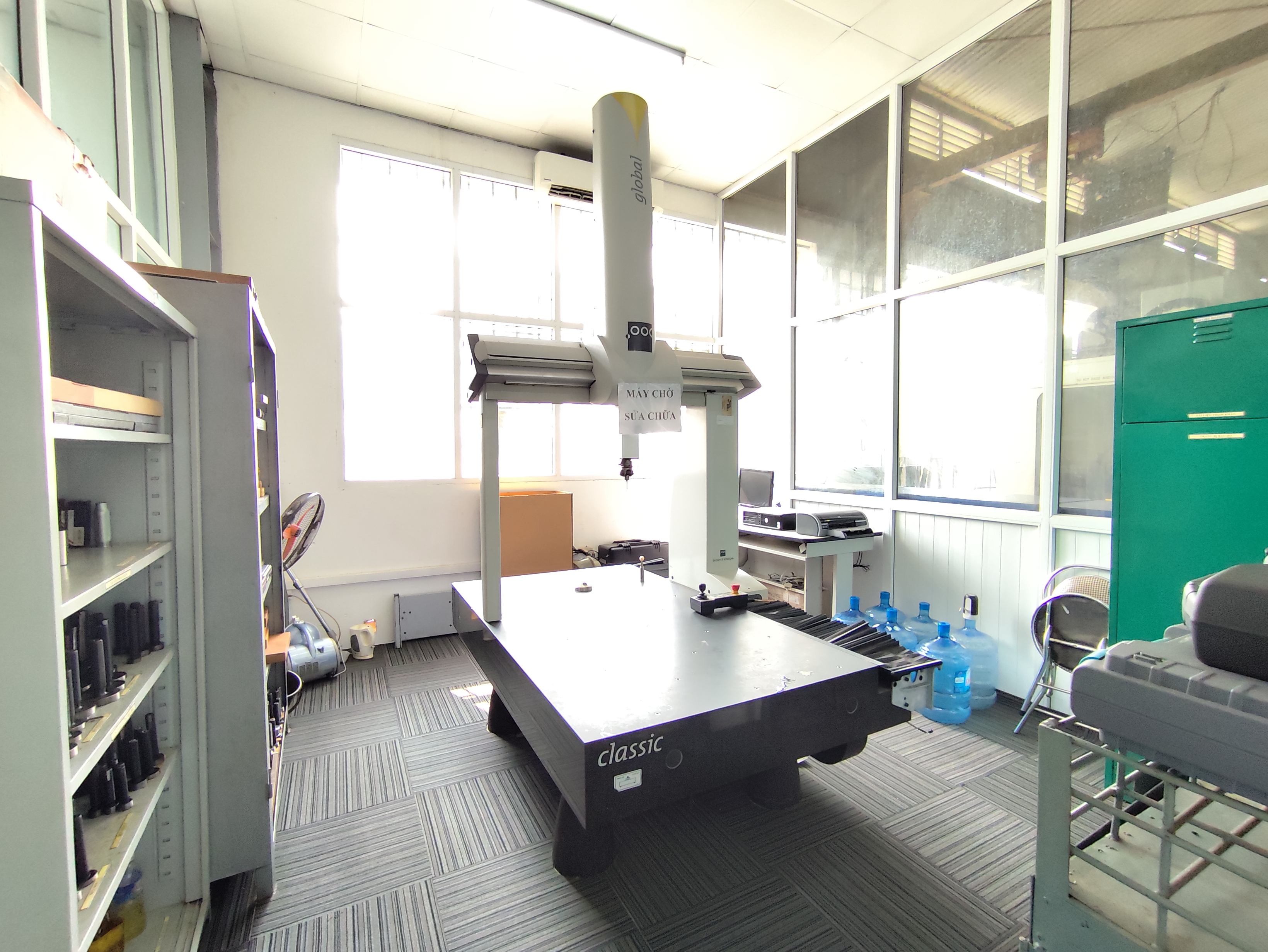
The simplest and most effective way to evaluate a QC team is to hand them your drawing and ask them to explain it back to you. Can they identify the datum references? Do they understand the difference between a bilateral tolerance and a unilateral tolerance? Can they read geometric dimensioning and tolerancing symbols like true position, flatness, and perpendicularity? During our supplier audits, we conduct this test live with the QC manager and at least one inspector. Their responses tell us immediately whether the team can handle the technical demands of the project.
Key Competencies to Assess
Here are the core skills and knowledge areas we evaluate:
- GD&T literacy: Can inspectors read and apply ASME Y14.5 9 or ISO 1101 symbology?
- Inspection planning: Does the team create a formal inspection plan that maps each critical dimension to a measurement method and piece of equipment?
- Equipment operation: Can inspectors operate the CMM, laser scanner, and other automated inspection systems without external assistance?
- Data interpretation: Can the team analyze measurement reports, identify trends, and make data-driven decisions about process adjustments?
- Problem escalation: Does the team know when to stop production and escalate a quality issue rather than shipping borderline parts?
Why This Matters for First-Time-Right Results
Our clients in the U.S. expect parts to be right the first time. Rework is expensive. Returns are worse. A QC team that misreads a drawing or uses the wrong measurement method will produce false passes—parts that appear to meet spec but actually do not. This creates downstream failures during assembly. When we onboard a new factory for a custom project, we invest time in training and aligning the QC team with our client's specific requirements. We review the drawing together, agree on the inspection plan, define pass/fail criteria, and run a trial inspection before production begins. You can learn more about how to create a sample testing plan to verify sheet metal fabrication capabilities in our dedicated guide. This upfront effort pays off in fewer rejections and faster delivery.
Evaluating Training and Certifications
Formal training matters. Ask whether QC inspectors have completed courses in metrology, blueprint reading, or quality management (such as ASQ certifications or internal training programs). Check if the factory maintains a training log. A well-run quality department documents who is trained on which equipment and which standards. Portable measuring arms and optical systems require specific training to use correctly. Without it, even expensive equipment produces unreliable data.
Conclusion
Evaluating quality inspection equipment and CMMs is not optional when sourcing precision sheet metal fabrication. Match inspection capability to part complexity, verify calibration, and always assess the people behind the machines.
Frequently Asked Questions
What specific inspection equipment should I look for to ensure my sheet metal parts meet tight tolerances?
A client once sent back an entire shipment of mounting brackets because hole positions drifted by 0.3mm. The supplier had checked parts with a tape measure. That experience taught our team to audit inspection equipment before approving any factory for precision work.
How can I verify that a supplier's CMM is properly calibrated for my custom project?
During a recent factory audit in Vietnam, I asked to see the CMM calibration certificate. The factory manager pointed to a sticker on the machine dated three years ago. That single observation saved our client from committing to a supplier whose measurement data could not be trusted.
Why is a CMM essential for the quality control of my complex sheet metal assemblies?
One trade-off we frequently discuss with clients involves cost versus risk. Skipping CMM verification on a $2 bracket seems reasonable. But when that bracket holds a sensor inside a $50,000 machine, a 0.2mm positional error becomes a $50,000 problem.
Footnotes
1. Wikipedia provides a comprehensive and authoritative definition of Coordinate Measuring Machines. ↩︎
2. Provides information on how laser cutters work in manufacturing. ↩︎
3. Explains the principles and importance of GD&T in engineering. ↩︎
4. Explains the requirements and importance of ISO 17025 accreditation for testing and calibration labs. ↩︎
5. Defines measurement uncertainty and its significance in metrology. ↩︎
6. Wikipedia explains Direct Computer Control (DCC) within the context of CMMs. ↩︎
7. Explains the process and importance of First Article Inspection in manufacturing. ↩︎
8. Explains the purpose and requirements of Production Part Approval Process (PPAP) documentation. ↩︎
9. Provides information on the ASME Y14.5 standard for dimensioning and tolerancing. ↩︎