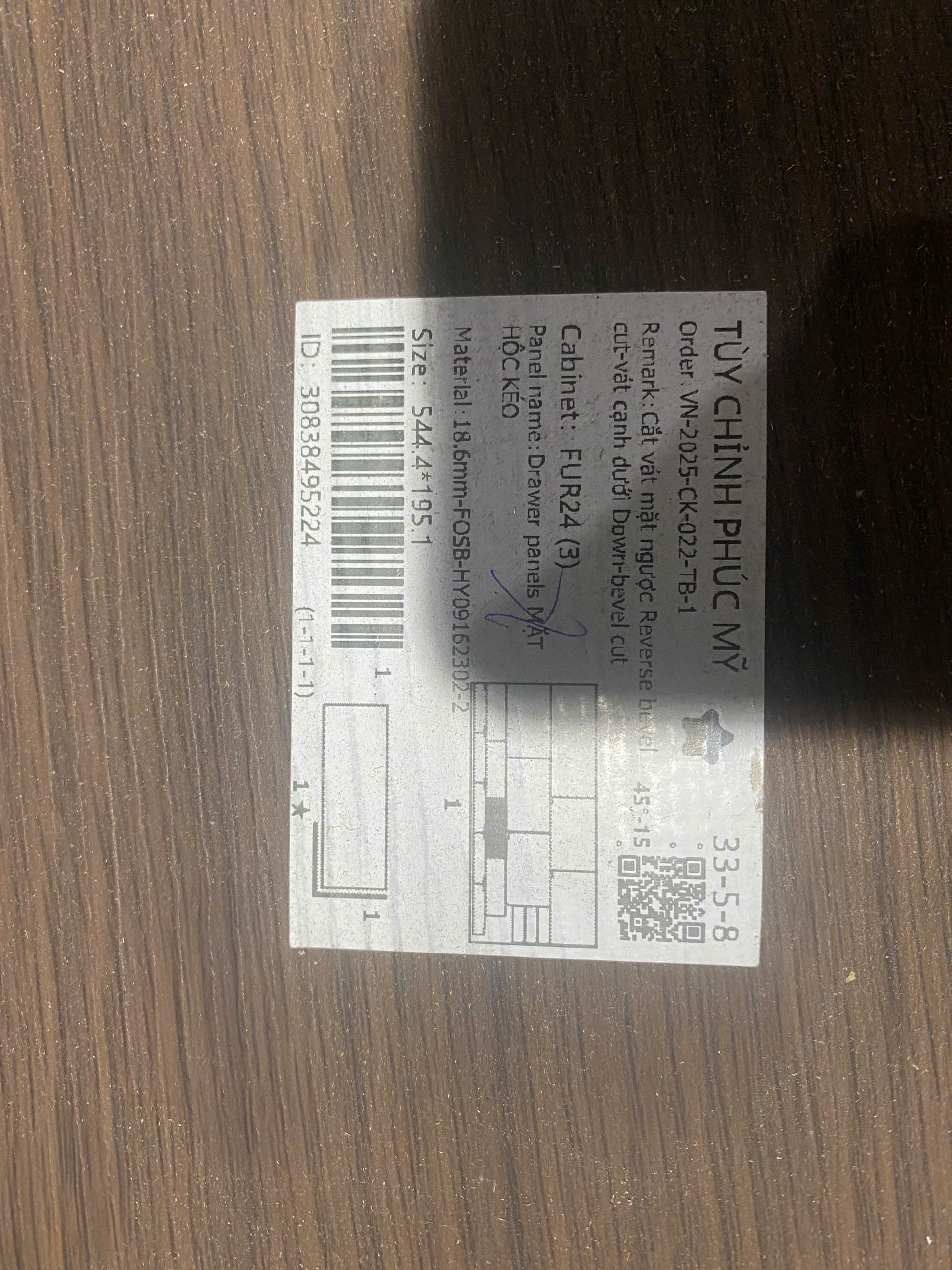

Production errors from unclear drawings cost our clients thousands in rework and delays every year. One ambiguous tolerance note on a stamping bracket drawing can cascade into a full batch of non-conforming parts 1 sitting in a Vietnamese warehouse.
To handle production errors from unclear drawings when sourcing stamping parts from Vietnam, you must freeze production immediately, perform a structured root cause analysis to separate drawing ambiguity from process failure, build a revision-controlled technical file package, and implement preventive DFM practices before re-launching the order.
This article walks through the exact steps we use at DEWIN to help U.S. buyers resolve and prevent these costly errors. Each section covers a specific stage — from diagnosis to prevention to supplier selection.
What Causes Drawing Misinterpretation When I Source Stamping Parts from Vietnamese Suppliers?
A lesson we learned early in our Vietnam office was that drawing misinterpretation rarely comes from a single cause. It usually grows from a chain of small gaps — a missing GD&T callout 2 here, a verbal clarification there — that compound until the stamped part no longer matches the buyer's intent.
Drawing misinterpretation happens when technical drawing specifications lack explicit GD&T standards, when tolerances are ambiguous, when material grades are undefined, and when Vietnamese shop-floor teams rely on informal verbal clarifications instead of controlled, revision-tracked documents.

The "Informal Clarification" Trap
In our experience coordinating between U.S. engineering teams and Vietnamese stamping shops, the single biggest cause of misinterpretation is what we call the "informal clarification" trap. Here is how it works: a buyer sends a drawing with an unclear bend radius note. The supplier calls or sends a WeChat message asking for clarification. The buyer replies verbally or in a chat. The supplier adjusts on the shop floor. The part passes inspection that time.
But nobody updates the drawing. Six months later, the same order restarts — maybe with a different shift supervisor or even a different supplier. The "truth" about that bend radius lives in someone's memory or a scribbled note on the shop floor, not in the controlled drawing file. The next batch fails.
This is not unique to Vietnam, but it is more common here because of language barriers and the tendency to prioritize speed over documentation. Many Vietnamese suppliers operate with strong technical skill but lean documentation habits.
Common Sources of Ambiguity
| Ambiguity Source | What Happens on the Shop Floor | How It Causes Defects |
|---|---|---|
| Missing GD&T symbols | Operators interpret flatness, perpendicularity, or positional tolerances by gut feeling | Holes misaligned, flanges out of spec |
| Undefined material grade | Supplier substitutes a "close enough" alloy | Springback differs, part dimensions shift |
| No burr direction callout | Burr side placed arbitrarily | Assembly interference, safety hazard |
| Tolerance applied uniformly | All dimensions held to the tightest tolerance | Cost spikes, unnecessary rejections |
| 2D drawing without 3D model | Complex multi-planar bends interpreted differently | Wrong bend sequence, cracking at corners |
Language and Translation Gaps
Technical translation is another friction point. The Vietnamese word for "tolerance" and "allowance" can overlap in casual use. A note saying "surface finish Ra 1.6 3" may be interpreted differently if the operator reads it as a target rather than a maximum. We always recommend bilingual documentation — English and Vietnamese — reviewed by a bridge engineer who understands both Western engineering standards and Vietnamese manufacturing vernacular.
When we onboard a new stamping supplier in Vietnam, our local team in Ho Chi Minh City walks the shop floor with the drawing and asks operators to explain what they see. If their interpretation does not match the buyer's intent, we flag it before a single die is cut. This simple step has saved multiple projects from first-article failure.
How Can I Prevent Production Errors Before My Stamping Parts Order Goes Into Manufacturing?
One of the trade-offs we constantly weigh is speed versus documentation rigor. Buyers want parts fast. But every week we invest in pre-production validation saves two or three weeks of rework downstream. Prevention is not a luxury — it is the cheapest form of quality control.
You can prevent production errors by creating a controlled file package with revision-tracked drawings, requiring CAE simulation before tooling, mandating First Article Inspection with CMM verification, and stratifying tolerances into critical, important, and non-critical groups to eliminate ambiguity.

The Controlled File Package
Before any RFQ leaves our office for a Vietnamese stamping supplier, we build what we call a "Controlled File Package." This is not just a drawing. It is a complete technical dossier that leaves no room for guessing. Here is what it includes:
| Package Component | Purpose | Format |
|---|---|---|
| Current drawing revision with revision history | Single source of truth for dimensions | PDF + native CAD file |
| 3D CAD model (STEP or IGES) | Eliminates 2D interpretation errors | STEP/IGES for CAD file conversion |
| Tolerance exception list | Flags which dimensions are critical vs. relaxed | Excel or embedded drawing notes |
| Material grade and finish specification | Prevents unauthorized substitution | Written spec block on drawing |
| Inspection plan | Defines what to measure, how, and when | Separate QC document |
| Limit samples and photos | Shows acceptable vs. rejectable parts | Physical samples + images |
| Gage correlation notes | Ensures supplier and buyer measure the same way | Gage R&R report |
This package travels with every order. When we transition a program from one supplier to another, this file is the bridge. It converts informal shop-floor knowledge into controlled data.
Tolerance Stratification
Not every dimension on a stamping bracket needs ±0.02mm precision. Experienced engineers group dimensions into three levels:
- Critical: Fit, sealing, and safety zones — hold tight tolerances, inspect 100%.
- Important: Moderate limits — sample inspect per AQL.
- Non-critical: Relaxed — visual check only.
This approach reduces cost and confusion. When a Vietnamese operator sees a drawing where every dimension carries the same tight tolerance, they either over-inspect (driving up cost) or give up and eyeball everything (driving up defects). Clear tolerances and material specs reduce guessing and protect both quality and cost.
CAE Simulation Before Tooling
The industry is shifting toward digital validation over physical guessing. We now require suppliers to run CAE software 4 — such as AutoForm — to simulate material flow, springback, and stress distribution before any tooling is cut. For stamping parts with multi-planar bends like the mounting brackets we source, springback compensation often requires an R-angle of 3x material thickness to avoid sharp corners that cause cracking. Catching this in simulation is far cheaper than discovering it after 10,000 parts are stamped.
First Article Inspection Protocol
We mandate a full First Article Inspection using a three-stage verification system: part check fixture to confirm the tolerance envelope, vision machine for feature location, and CMM 5 for precise dimensioning. This prototype validation step catches errors before mass production begins. No mass production starts until the first piece passes all three checks and the buyer signs off.
What Should I Do When I Receive Non-Conforming Stamping Parts Due to Unclear Drawings?
Last quarter, a U.S. client called us about a shipment of stamping clips that arrived with slotted holes 0.3mm off-center. The parts looked fine visually, but they would not align with the mating assembly. The root cause was not a machine error — it was a missing positional GD&T callout on the drawing. Here is the process we followed to resolve it.
When you receive non-conforming stamping parts, you must immediately freeze production, conduct a structured manufacturing defect analysis to isolate drawing ambiguity from process failure, document findings with a root cause corrective action report, and update the controlled file package before re-launching production.

The 4-Step "Stop-Launch" Protocol
Never guess. Even when remedial action based on a guess corrects the problem, nothing really has been learned that could be used for future reference. We follow a strict four-step protocol:
Step 1: Freeze the process. Stop production immediately. Do not allow the supplier to "fix it on the fly." Compounding errors by continuing production turns a recoverable situation into a catastrophe.
Step 2: Symptom study. Document exactly what changed and where the defect appears. Is it wrinkling? Cracking? Dimensional drift? Take photos, measurements, and compare against the approved first article. Our QC team in Vietnam uses standardized defect reporting forms that capture the part number, revision, cavity, defect type, and measurement data.
Step 3: Isolate variables. Before blaming the drawing, check process variables. Was the punch speed changed? Was the material lot different? Was the die recently ground? Die maintenance intervals should be standardized — grinding every 50,000 punchings is the industry norm for preventing progressive defects. If all process variables are stable, the root cause likely traces back to drawing ambiguity.
Step 4: First piece re-inspection. Run a new first piece and inspect it with a 3D scanner against the digital model. If it matches the drawing but not the buyer's intent, the drawing is the problem — not the supplier.
Distinguishing Drawing Error from Process Error
| Indicator | Drawing Ambiguity | Process Failure |
|---|---|---|
| Defect consistent across all parts | Yes — every part has the same issue | No — defect is random or progressive |
| First article also had the issue | Often yes, but was overlooked | No — first article was conforming |
| Process variables changed | No | Yes — material, speed, or tooling shifted |
| Supplier's interpretation matches the drawing | Yes — they read it as written | No — they deviated from the drawing |
| Fix requires drawing update | Yes | No — fix requires process adjustment |
This distinction matters because the corrective action is completely different. If the drawing is the problem, re-working the current batch is only a temporary fix. The next batch will fail again unless you update the drawing and re-freeze the technical package.
Managing Customs and Logistics for Reworked Parts
One risk many buyers overlook is the customs impact. If parts are reworked in Vietnam, the country of origin documentation must be consistent. Mismatches between the commercial invoice, packing list, and certificate of origin can trigger shipment holds at U.S. customs. We always verify HTS codes 7 and origin statements before shipping reworked or replacement parts. This is especially important when parts move between facilities within Vietnam for rework, as it can create documentation gaps.
The CAPA Loop
After resolving the immediate defect, we close the loop with a formal Corrective and Preventive Action 8 process. The drawing gets updated with a new revision number. The tolerance exception list gets revised. The inspection plan gets tightened for the affected dimension. And most importantly, the supplier's quality team reviews the updated package and signs off before the next production run begins. This is supplier quality management in practice — not just a certificate on the wall.
How Do I Choose a Vietnam Stamping Supplier That Won't Misread My Technical Drawings?
During a recent supplier audit in Binh Duong province, we visited a stamping shop that had brand-new progressive dies 9, clean floors, and impressive equipment. But when we handed them a drawing with GD&T callouts, the engineering manager admitted his team had never worked with geometric tolerancing — they only used linear dimensions. Equipment alone does not make a capable supplier.
Choose a Vietnam stamping supplier by evaluating their technical drawing literacy, GD&T competency, quality control protocols, revision management systems, CAE simulation capability, and willingness to conduct formal First Article Inspections with CMM and documented PPAP submissions.

What to Evaluate Beyond the Factory Tour
Most buyers evaluate suppliers based on equipment lists and ISO 9001 certification. Those matter, but they do not tell you whether the supplier can correctly interpret your technical drawing specifications. Here is what we look for during our supplier audits:
Drawing literacy test. We bring a sample drawing with intentional complexity — a multi-planar bracket with GD&T callouts, material grade verification requirements, and a specific burr direction note. We ask the supplier's engineering team to walk us through what they see. If they miss the positional tolerance or cannot explain the material spec, they are not ready for the project.
Revision control system. We check whether the supplier has a formal system for tracking drawing revisions. Do they use a centralized document control system, or do drawings float around on USB drives and personal email? A supplier who cannot tell you which revision they are working from will eventually produce parts to an outdated drawing.
Inspection capability. We verify their metrology equipment — CMM, optical comparators, surface roughness testers — and check calibration records. A three-stage verification system (check fixture, vision machine, CMM) is the gold standard for metal stamping tolerances.
Supplier Selection Scorecard
| Evaluation Criteria | Weight | What to Look For |
|---|---|---|
| GD&T literacy | 20% | Can the engineering team read and apply geometric tolerancing? |
| Revision control system | 15% | Is there a formal document control process with revision tracking? |
| Metrology equipment | 15% | CMM, vision system, check fixtures — calibrated and in use? |
| CAE simulation capability | 10% | Do they use AutoForm 10 or equivalent for springback and material flow? |
| PPAP / FAI process | 15% | Can they produce a formal First Article Inspection report? |
| Communication responsiveness | 10% | Do they respond to technical queries within 24 hours with written answers? |
| Bridge engineer availability | 10% | Is there a bilingual technical liaison who can mediate drawing disputes? |
| Tooling ownership clarity | 5% | Is die, fixture, and gage ownership explicitly defined in the contract? |
The Bridge Engineer Advantage
One of the most effective investments a buyer can make is embedding a local technical liaison — what we call a "bridge engineer" — who understands both Western engineering standards and Vietnamese manufacturing vernacular. Our team in Vietnam fills this role for our clients. When a drawing note says "break all sharp edges," the bridge engineer translates that into a specific deburring instruction with a measurable radius. When the buyer says "hold this flat to 0.1mm," the bridge engineer confirms whether the supplier's check fixture can verify that.
The Golden Sample System
For ongoing production, we implement a "Golden Sample" system. A signed physical master part is kept on the factory floor as the primary reference point for quality control. This supersedes the drawing in cases of minor ambiguity. The Golden Sample is measured, photographed, and documented in the controlled file package. When a new shift starts, operators compare their output against the Golden Sample — not just the drawing. This is especially useful for stamping parts with complex bends where the 2D drawing cannot fully capture the three-dimensional intent.
Tooling Ownership — Settle It Upfront
Buyers should not wait until the relationship ends to confirm who owns the die, which files are current, and what evidence must move with the program. In Vietnam, tooling transfer can be legally ambiguous. We photograph all tooling before any movement and mark ownership clearly. If you ever need to transition to a new supplier, having documented tooling ownership saves weeks of negotiation and potential legal disputes. We also maintain a bridge inventory — enough parts to cover the qualification gap while the new supplier ramps up.
Conclusion
Handling production errors from unclear drawings starts with recognizing that the drawing itself is often the root cause — not the supplier's skill. Freeze production, isolate the real problem, build a controlled file package, and choose suppliers who can truly read your technical intent. Prevention always costs less than correction. For further guidance, learn how to avoid drawing communication errors when sourcing sheet metal fabrication and how to establish effective incoming inspection standards for stamping parts.
Frequently Asked Questions
What Causes Drawing Misinterpretation When I Source Stamping Parts from Vietnamese Suppliers?
A lesson we learned early in our Vietnam office was that drawing misinterpretation rarely comes from a single cause. It usually grows from a chain of small gaps — a missing GD&T callout 2 here, a verbal clarification there — that compound until the stamped part no longer matches the buyer's intent.
How Can I Prevent Production Errors Before My Stamping Parts Order Goes Into Manufacturing?
One of the trade-offs we constantly weigh is speed versus documentation rigor. Buyers want parts fast. But every week we invest in pre-production validation saves two or three weeks of rework downstream. Prevention is not a luxury — it is the cheapest form of quality control.
What Should I Do When I Receive Non-Conforming Stamping Parts Due to Unclear Drawings?
Last quarter, a U.S. client called us about a shipment of stamping clips that arrived with slotted holes 0.3mm off-center. The parts looked fine visually, but they would not align with the mating assembly. The root cause was not a machine error — it was a missing positional GD&T callout on the drawing. Here is the process we followed to resolve it.
Footnotes
1. Authoritative Wikipedia article defining nonconformity within quality management systems. ↩︎
2. Authoritative guide on Geometric Dimensioning and Tolerancing symbols and callouts used in engineering drawings. ↩︎
3. ISO standard for surface texture and roughness parameters like Ra, essential for technical drawing accuracy. ↩︎
4. Overview of Computer-Aided Engineering software used for digital validation and simulation in manufacturing. ↩︎
5. Comprehensive Wikipedia entry for Coordinate Measuring Machines (CMM) used in precision metrology. ↩︎
6. Official ISO page explaining the requirements and benefits of the ISO 9001 quality management standard. ↩︎
7. Official U.S. International Trade Commission portal for Harmonized Tariff Schedule codes required for customs documentation. ↩︎
8. FDA guidance on CAPA, a fundamental quality management process for resolving production errors. ↩︎
9. Wikipedia explanation of progressive stamping and the use of progressive dies in metal part production. ↩︎
10. Official site of the industry-leading software for sheet metal forming simulation and process validation. ↩︎