
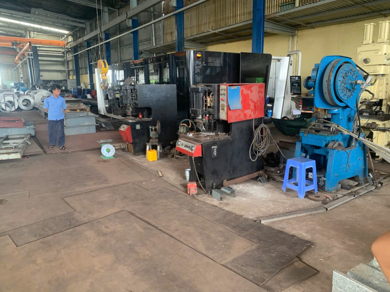
The hardness index of stamped parts nearly derailed one of our bracket projects. The parts looked perfect. Then they cracked at assembly, and our team traced it back to hardness.
The hardness index of stamped parts is measured by indentation testing, most commonly the Rockwell method. A standardized indenter is pressed into the part under controlled loads, and the penetration depth or indentation size is converted into a hardness number such as HRB, HRC, HBW, or HV.
That is the short answer. But the method your supplier picks, the way they prepare the surface, and the numbers on your drawing all change the result. Let me walk you through each part.
What Testing Methods Do Suppliers Use to Measure Hardness on My Stamped Parts?
During a supplier audit in Vietnam last year, I watched a technician test a thin mounting clip on a standard Rockwell machine. The reading was wrong. The part was simply too thin for that scale, and it taught our client a useful lesson.
Suppliers measure hardness on stamped parts using three main indentation methods: Rockwell for fast production checks, Brinell for thicker parts needing an averaged reading, and Vickers for thin gauges, coatings, and small features. Portable Leeb testers handle large or oddly shaped stampings that cannot fit benchtop machines.
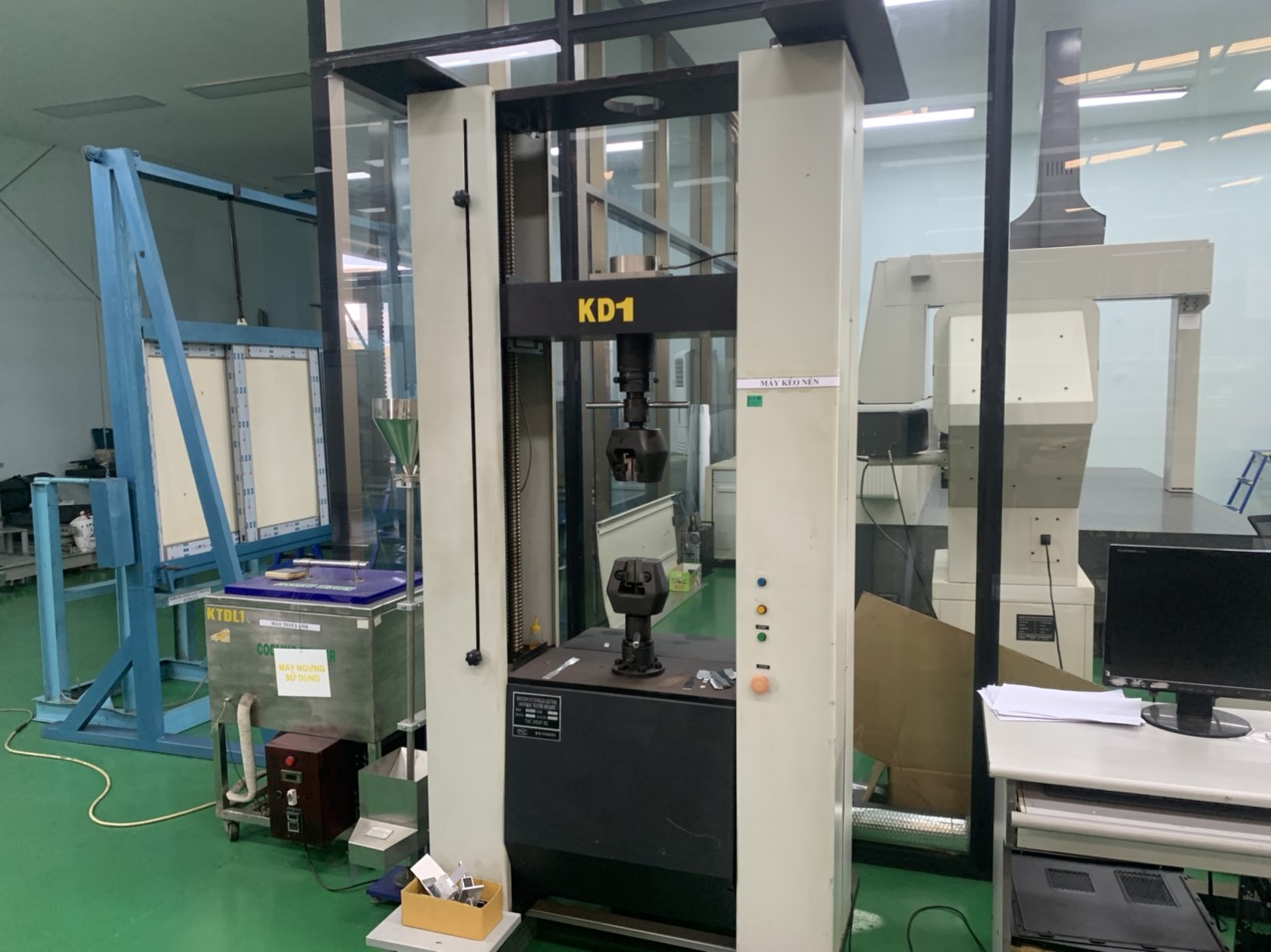
Each method presses an indenter into the metal and turns the result into a number. But they differ in speed, precision, and the parts they suit. Here is how I explain it to purchasing managers who source stamped brackets and clips through us.
The Three Core Methods Compared
| Method | Indenter | What Is Measured | Best For Stamped Parts | Standard |
|---|---|---|---|---|
| Rockwell (HRB/HRC) | Diamond cone or steel ball | Depth difference between minor and major load | Routine production QC on most steel stampings | ASTM E18 1 / ISO 6508 |
| Brinell (HBW) | Hardened steel or carbide ball | Diameter of the indentation | Thicker, larger parts needing an averaged value | ASTM E10 |
| Vickers (HV) | 136° diamond pyramid | Diagonal lengths of the imprint, read optically | Thin gauges, small tabs, coatings, bend zones | ASTM E92 |
How Rockwell Works Step by Step
Rockwell is the workhorse for stamped parts. The tester first applies a minor preload to seat the indenter. Then it adds the major load for a set dwell time. Finally, it drops back to the minor load and reads the depth difference. The machine converts that depth into a hardness number instantly. No optical reading is needed. That is why it dominates production lines.
When Vickers Wins
Vickers uses very low loads and a tiny diamond pyramid. So it can test thin sheet, plated surfaces, and small stamped features without punching through or distorting the reading. When we validate galvanized clips like the ones we ship to the US, Vickers microhardness 2 is often the only honest option. Knoop microhardness goes one step further. It can map hardness gradients across a bend radius, where stamping itself has work-hardened the metal.
Why Does Hardness Consistency Matter for the Quality of My Custom Stamped Parts?
A US client once asked me why two batches of identical brackets behaved differently at installation. One batch bent cleanly. The other cracked. The drawings were identical. The hardness was not.
Hardness consistency matters because it confirms uniform material condition and heat treatment across a batch. Inconsistent hardness produces parts that are too soft to hold load or too brittle to form, causing cracked flanges, worn holes, field failures, and costly rework at assembly.
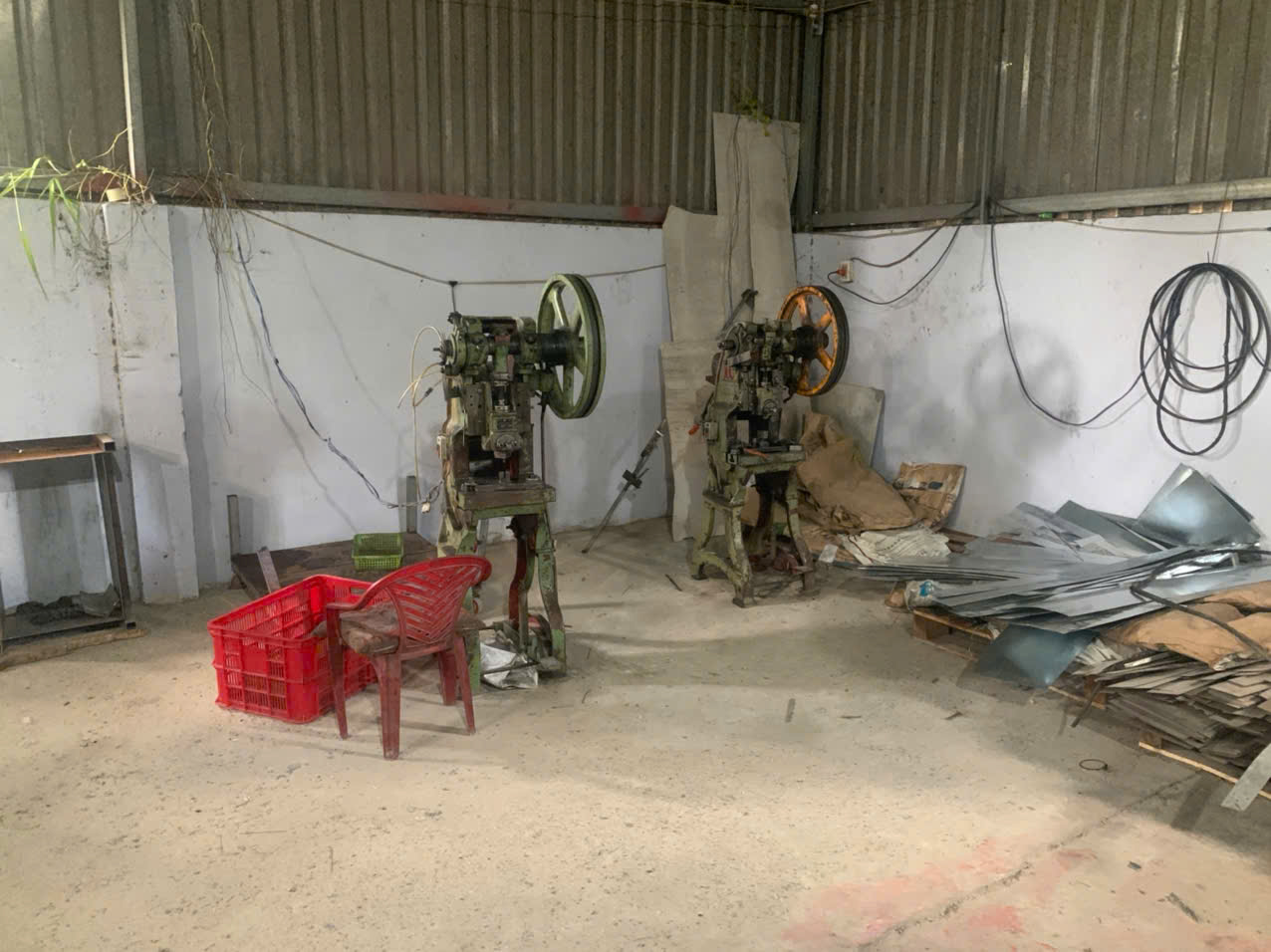
Hardness is a proxy. It does not measure stamping quality directly. Instead, it measures resistance to permanent deformation, which correlates with tensile strength, wear resistance, and formability. So when hardness drifts, something upstream has changed. That is the real value of tracking it.
What Hardness Drift Actually Tells You
In my experience running process control for custom parts, hardness variation usually points to one of four root causes:
- Raw material lot change. A new coil with different chemistry or temper.
- Heat treatment drift. Furnace temperature or quench timing has shifted heat treatment 4.
- Tool and die wear. Worn dies change how much the metal work-hardens during forming.
- Process shortcuts. A supplier skipping stress relief or annealing to save time.
Any of these can pass a visual inspection. None of them can hide from a proper hardness check.
Work Hardening Makes Stampings Special
Here is a point many buyers miss. Stamping itself changes hardness. Bending, drawing, and punching all work-harden the metal locally. So a flat flange and a tight bend radius on the same bracket can read quite differently. That is normal. What matters is that the pattern stays consistent from batch to batch. A single reading in the center of a part tells you very little. We ask our audited suppliers to test multiple points and to feed those readings into statistical process control charts. That way, tool wear or a bad material lot shows up in the data before dimensional defects appear on the line. For clients like Greg, who cannot afford rework after import, this early warning is worth far more than the cost of the testing.
How Can I Verify That My Supplier's Hardness Test Reports Are Accurate?
Trust, then verify. That is the rule our sourcing team follows on every custom parts project, because we have seen reports that were copied batch after batch without a single new measurement being taken.
Verify hardness reports by checking tester calibration certificates against ASTM or ISO standards, confirming the correct scale for the part thickness, requiring multiple test locations per part, cross-checking with independent third-party lab tests, and auditing whether raw data matches the report values.

A report is only as good as the process behind it. When our engineers audit stamping suppliers in Vietnam and across Asia, we run through a specific verification checklist. You can use the same one, even from a distance.
The Verification Checklist
| Check | What to Ask For | Red Flag |
|---|---|---|
| Calibration | Current calibration certificate for the tester, plus daily checks with certified test blocks 6 | Certificate expired or missing test-block records |
| Standard compliance | Confirmation of ASTM E18, E10, E92, or ISO 6508 procedure | No standard referenced on the report |
| Scale suitability | Justification of the scale (e.g., HRB vs. HR15T) for your part thickness | Standard Rockwell scale used on thin-gauge sheet |
| Sampling | Number of parts tested per lot and locations per part | Single reading per batch, always identical values |
| Surface prep | Description of cleaning and preparation before testing | Testing over coating, scale, or burrs without noting it |
| Traceability | Raw data logs linked to lot numbers | Report values with no underlying data |
Practical Steps From a Buyer's Chair
First, ask for photos or video of the actual test during production. Honest suppliers share this freely. Second, order a third-party lab test on a small sample from your first shipment. Compare the lab values against the supplier report. Small differences are normal. Large gaps are not. Third, watch the numbers over time. Real measurement data has natural scatter. If every report shows the exact same value, someone is copying and pasting. Finally, build hardness verification into your PPAP requirements 7. We do this on every co-development project, and it forces the measurement discipline in place before mass production ever starts.
What Hardness Specifications Should I Include in My Drawings When Sourcing Stamped Parts?
Vague drawings cause most of the hardness disputes I have mediated between US buyers and Asian factories. A note that just says "hardened" leaves every critical decision to the supplier, and that rarely ends well.
Your drawings should specify the hardness scale and range (e.g., HRC 40–45), the test method and standard (e.g., ASTM E18), test locations on the part, the number of readings required, the material condition or heat treatment state, and acceptance criteria for out-of-range readings.

A complete hardness callout removes ambiguity. It also protects you commercially, because a clear spec makes non-conformance easy to prove and easy to reject. Here is what I recommend putting on every stamped part drawing.
The Six Elements of a Complete Hardness Callout
| Element | Example | Why It Matters |
|---|---|---|
| Scale and range | HRC 40–45, or HV 180–220 | A number without a scale is meaningless; a range beats a single target |
| Test method and standard | Rockwell per ASTM E18 | Locks in procedure and calibration requirements |
| Test location | On flat flange, min 3 mm from edge or bend | Avoids readings distorted by work hardening or edge effects |
| Number of readings | 3 readings per part, 5 parts per lot | Controls variability and defines the sampling plan |
| Material condition | Quenched and tempered; or as-stamped, no anneal | Ties hardness to the process that produces it |
| Acceptance rule | All readings within range; retest protocol defined | Prevents arguments over a single outlier |
Match the Range to the Job
Do not copy a hardness range from another project. Match it to function. A spring clip needs enough hardness to hold grip force over thousands of cycles. A structural bracket needs a balance of strength and ductility so it will not crack at the bend. A galvanized mounting part may need testing on the base metal, not the coating, and your drawing should say so explicitly. Also state the thickness-appropriate scale. For sheet under about 1 mm, call out a superficial Rockwell scale or Vickers rather than standard HRC. During our OEM co-development work, we review every hardness callout against the material datasheet and the forming process before the drawing is released. Ten minutes of review at that stage saves weeks of dispute later.
Conclusion
Wrong hardness means cracked flanges, failed assemblies, and returned shipments. The fix is simple: specify the scale, method, locations, and range clearly, then verify your supplier's reports. Feel free to reach out if you want help doing exactly that.
Frequently Asked Questions
What Testing Methods Do Suppliers Use to Measure Hardness on My Stamped Parts?
During a supplier audit in Vietnam last year, I watched a technician test a thin mounting clip on a standard Rockwell machine. The reading was wrong. The part was simply too thin for that scale, and it taught our client a useful lesson.
Why Does Hardness Consistency Matter for the Quality of My Custom Stamped Parts?
A US client once asked me why two batches of identical brackets behaved differently at installation. One batch bent cleanly. The other cracked. The drawings were identical. The hardness was not.
How Can I Verify That My Supplier's Hardness Test Reports Are Accurate?
Trust, then verify. That is the rule our sourcing team follows on every custom parts project, because we have seen reports that were copied batch after batch without a single new measurement being taken.
Footnotes
1. Provides background on the Rockwell hardness scale referenced throughout the article. ↩︎
2. Explains the Vickers hardness test method used for thin gauges and coatings. ↩︎
3. Background on the Brinell hardness test standard mentioned for thicker parts. ↩︎
4. ISO reference standard body relevant to heat treatment and hardness testing procedures. ↩︎
5. Explains the metallurgical phenomenon of work hardening central to the article’s discussion. ↩︎
6. NIST supplies certified reference materials used to verify hardness tester calibration accuracy. ↩︎
7. Defines the Production Part Approval Process referenced for supplier verification. ↩︎