

Material thickness quietly decides whether stamping parts succeed or fail. On our production line, I have watched a 0.2 mm gauge difference turn a perfect bracket run into a scrap bin problem.
Material thickness directly affects stamping parts performance by changing forming force, springback, thinning, and tool wear. Thinner stock forms faster and cheaper but risks wrinkling and warping, while thicker stock adds strength and stiffness but demands higher tonnage, wider tolerances, and stronger tooling.
That trade-off shapes every stamping decision. Below, I break down how thickness affects tolerances, defects, costs, and metal-specific guidelines so you can specify the right gauge with confidence.
How can I choose the right material thickness for my stamping tolerances?
A U.S. purchasing manager once sent our team a bracket drawing with ±0.05 mm bend tolerances on 3 mm steel. Our engineers flagged it immediately—thickness and tolerance must be matched, not chosen separately.
Choose material thickness by matching part function to achievable tolerances: thinner gauges (0.5–1.5 mm) hold tighter bend tolerances with less press force, while thicker gauges (2–6 mm) need wider tolerances to absorb springback. Always confirm your supplier's gauge tolerance, not just nominal thickness.

Thickness and tolerance work as a pair. If you pick one without the other, you invite trouble at the press. Stamping is generally most efficient between 0.127 mm and 6.35 mm for common sheet alloys. Inside that window, thinner material usually holds dimensions more predictably on simple bends. Thicker material stores more elastic energy, so it springs back harder after forming. That springback 1 must be compensated in the die, and compensation is never perfect across a full production run.
There is a second layer many buyers miss. The raw sheet itself arrives with a thickness tolerance from the mill. A "1.0 mm" coil may legally run from 0.95 mm to 1.05 mm. Punch-to-die clearance 2 is set around nominal thickness, so this variation changes edge quality, burr height, and bend angles from lot to lot. In our supplier audits across Vietnam and Taiwan, checking incoming gauge consistency is one of the first process controls we verify.
Practical selection steps
- Define the loads the part must carry, then set a minimum structural thickness.
- Check the tightest tolerance on your drawing against that gauge's springback behavior.
- Ask for the mill's thickness tolerance band, not just the nominal value.
- Confirm your stamper's press tonnage covers the chosen gauge with margin.
| Nominal Thickness | Typical Achievable Bend Tolerance | Springback Risk | Best For |
|---|---|---|---|
| 0.5–1.0 mm | ±0.1 mm | Moderate (warping) | Clips, shields, light brackets |
| 1.0–2.0 mm | ±0.15 mm | Moderate | General mounting hardware |
| 2.0–4.0 mm | ±0.25 mm | High | Structural brackets |
| 4.0–6.35 mm | ±0.4 mm or wider | Very high | Heavy load supports |
What thickness issues cause defects or failures in my stamped parts?
During a final inspection in our Vietnam office last year, we traced a batch of cracked mounting clips back to one root cause: bend radii specified below the material's thickness. The drawing looked fine. The physics did not agree.
The main thickness-related defects are cracking at bends tighter than 1x thickness, wrinkling and warping in thin gauges, excessive thinning during deep draws, oversized burrs from mismatched punch-die clearance, and cumulative dimensional drift when gauge varies across progressive stamping stations.

Each defect ties back to thickness in a specific way. Understanding the mechanism helps you prevent it at the design stage instead of discovering it at final QC.
Cracking and thinning
Bend radii smaller than 1.0T overstress the outer fiber of the bend. The material stretches past its limit and cracks. Deep drawing 3 adds another risk: the sheet thins as it flows into the die. Research shows thinning increases as blank thickness decreases in many operations. Interestingly, thicker blanks can extend the forming limit—in one hot-stamping study, a 1.2 mm sheet drew deeper without breaking than a 1.0 mm sheet under identical conditions. FEA forming simulation 4 now catches these failure zones before tooling is cut, flagging thinning that exceeds the 20–30% safety threshold.
Wrinkling, warping, and burrs
Thin stock lacks the stiffness to resist compressive stresses during forming. It wrinkles in flanges and warps after release. Burrs grow when punch-die clearance no longer matches actual sheet thickness. Since clearance is calculated as a percentage of thickness, a thicker-than-nominal coil effectively tightens the clearance and tears the edge.
Cumulative drift in progressive dies
Progressive tooling compounds small errors. Inconsistent gauge shifts strain at every station, and the drift often stays hidden until final inspection. That is why we insist on gauge checks at receiving, not just at the end of the line.
| Defect | Thickness-Related Cause | Prevention |
|---|---|---|
| Bend cracking | Radius below 1.0T | Specify radius at 1.0–1.5T |
| Wrinkling | Gauge too thin for flange depth | Increase gauge or add blank holder force |
| Excessive thinning | Thin blank in deep draw | Simulate; keep thinning under 20–30% |
| Heavy burrs | Clearance mismatched to actual gauge | Control incoming thickness tolerance |
| Dimensional drift | Gauge variation across stations | Lot-level gauge verification |
How does material thickness impact tooling costs and production time for my project?
One trade-off comes up in almost every quotation our team prepares: a client wants a thicker gauge "to be safe," and the tooling price jumps before a single part is stamped. Thickness is a cost multiplier, not just a material line item.
Thicker material raises tooling costs and slows production because it demands higher press tonnage, stronger die steels, wider clearances, and more frequent tool maintenance. Thinner material cuts force, speeds cycles, and extends die life—but only if it avoids wrinkling and scrap-driven rework.

The cost chain starts at the press. Forming force scales with thickness and material strength. Doubling the gauge can push a job from a small mechanical press to a much larger machine, and larger presses carry higher hourly rates. The die itself must also be built heavier. Cutting sections need tougher tool steel, thicker die plates, and more robust guiding to survive the higher shock loads. That adds engineering hours and material cost before production even starts.
Then comes wear. Every stroke through thick, hard stock abrades punches and dies faster. Sharpening intervals shorten. In high-volume programs, tool maintenance downtime becomes a real schedule risk. When we manage contract manufacturing for U.S. clients, we build regrind schedules into the production plan precisely because a missed maintenance window on thick-gauge tooling can stall an entire shipment—and delivery delays are the pain point our clients tolerate least.
Thin stock flips the equation. Lower tonnage, faster strokes, longer tool life, lighter shipping weight. But if the gauge drops below what the geometry can support, scrap rates climb, and scrap erases every saving. There is also a downstream factor: thinner parts warp more under thermal load during welding, plating, or powder coating, which can add straightening or fixturing costs later.
Where the money actually goes
- Press tonnage and machine rate rise with thickness.
- Die construction cost rises with the shock loads of thick stock.
- Maintenance frequency rises with abrasive wear per stroke.
- Scrap cost rises when thin stock wrinkles or fails tolerance.
- Raw material cost rises roughly in proportion to gauge and weight.
The right answer is rarely the thickest "safe" option or the thinnest "cheap" option. It is the lightest gauge that meets function with margin, verified by simulation before tooling is cut.
Which thickness guidelines should I follow for different metals in my custom stamping parts?
Reviewing drawings for custom stamping parts is a daily task for our engineering team, and one lesson repeats: guidelines that work for mild steel do not transfer directly to stainless, aluminum, or brass. Each metal forms, springs, and wears differently at the same thickness.
Follow metal-specific rules: keep bend radii at 0.5–1x thickness for aluminum and mild steel, 1–2x for stainless steel; space holes at least 2x thickness from bend radii; keep features 1.5x thickness apart; and stay within the 0.127–6.35 mm efficient stamping window.
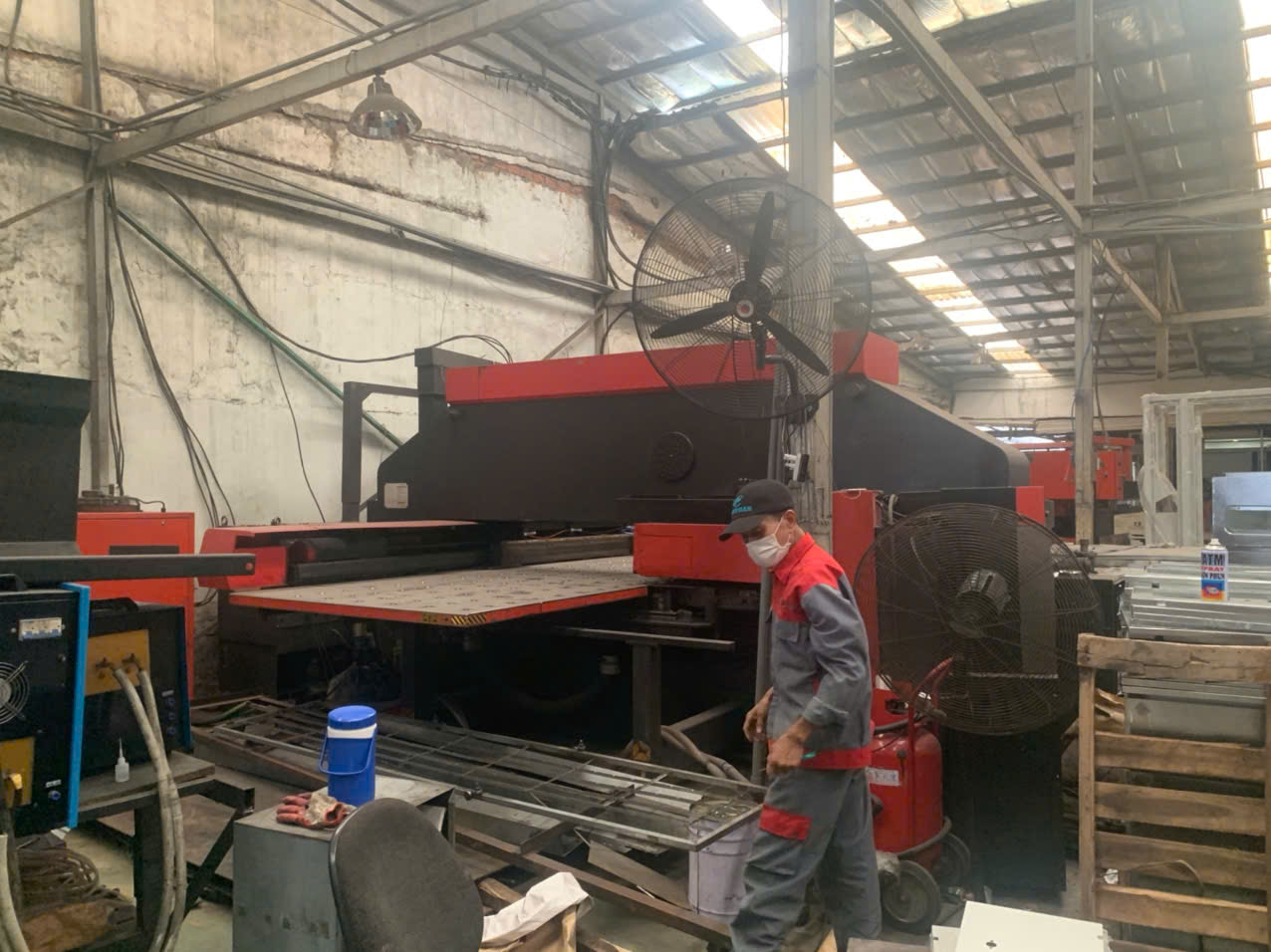
Design rules scale with thickness because strain scales with thickness. A hole placed too close to a bend distorts as the material stretches. A slot too close to an edge tears during blanking. The common rules of thumb are: keep trimmed or perforated features at least 1.5x material thickness apart, and keep holes at least 2x thickness away from a formed feature's radius. These rules protect you across all metals, but the bend radius rule shifts by alloy.
Metal-by-metal comparison
| Metal | Common Stamping Gauge Range | Minimum Bend Radius | Key Thickness Consideration |
|---|---|---|---|
| Mild / low-carbon steel | 0.5–6.0 mm | 0.5–1.0T | Forgiving; widest process window |
| Stainless steel | 0.4–3.0 mm | 1.0–2.0T | High springback; work-hardens 5 fast |
| Aluminum (5052 type) | 0.5–4.0 mm | 0.5–1.0T | Light but prone to cracking in hard tempers |
| Brass / copper | 0.3–2.5 mm | 0.5–1.0T | Excellent formability; watch electrical specs |
| Galvanized steel 6 | 0.5–3.0 mm | 1.0T | Coating cracks on tight bends |
Function-driven adjustments
Guidelines set the floor; function sets the final number. Load-bearing brackets need enough section to resist bending and hold threads—thin sheet strips fasteners easily. For electrical or EMI-shielding components 7, thickness variation changes current-carrying capacity and magnetic permeability, so consistency matters beyond mechanics. For lightweight consumer or automotive parts, push toward the thin end, but validate stiffness first. When our team co-develops parts with U.S. engineering firms, we run these checks during DFM review, because catching a thickness mismatch on paper costs nothing compared to catching it in PPAP.
Conclusion
Material thickness drives strength, tolerances, defects, and cost in stamping parts. Get the gauge wrong and you pay in scrap, tooling wear, and delays. Specify it with function, metal-specific rules, and simulation—and your parts arrive right the first time.
Frequently Asked Questions
How can I choose the right material thickness for my stamping tolerances?
A U.S. purchasing manager once sent our team a bracket drawing with ±0.05 mm bend tolerances on 3 mm steel. Our engineers flagged it immediately—thickness and tolerance must be matched, not chosen separately.
What thickness issues cause defects or failures in my stamped parts?
During a final inspection in our Vietnam office last year, we traced a batch of cracked mounting clips back to one root cause: bend radii specified below the material's thickness. The drawing looked fine. The physics did not agree.
How does material thickness impact tooling costs and production time for my project?
One trade-off comes up in almost every quotation our team prepares: a client wants a thicker gauge "to be safe," and the tooling price jumps before a single part is stamped. Thickness is a cost multiplier, not just a material line item.
Footnotes
1. Wikipedia explains the elastic recovery phenomenon central to thickness discussion. ↩︎
2. Background concept on stamping die clearance mechanics referenced in the article. ↩︎
3. Wikipedia background on the deep drawing forming process mentioned in defects section. ↩︎
4. ISO standards relate to simulation and quality control practices in manufacturing. ↩︎
5. Explains the metallurgical phenomenon affecting stainless steel forming behavior noted in table. ↩︎
6. Wikipedia background on galvanized coating referenced in the metal comparison table. ↩︎
<span id="footnote-