
Measuring hardness indicators of stamping parts sounds simple, until a batch fails at your customer’s dock. I have watched that happen, and our QC team rebuilt our whole testing process because of it.
Hardness indicators of stamping parts are measured with indentation tests—mainly Rockwell, Brinell, and Vickers. Choose the method by material, thickness, and geometry; clean and flatten the surface; apply the specified load; then take readings at several points and average the results.
That is the short answer. But the details decide whether your data is trustworthy. Below, I walk through the methods, standards, equipment, and supplier verification steps we use on real custom-part projects.
What Hardness Testing Methods Should I Use for Stamping Parts?
A few years back, our Vietnam office received a set of thin-gauge steel clips that kept failing Rockwell checks. The parts were fine. The test method was wrong. That project taught our team to match the method to the part first.
Use Rockwell for fast production checks on most stamped steel parts, Brinell for softer or coarser materials needing an averaged reading, and Vickers or Knoop micro-hardness for thin sheet, coatings, and localized zones. Part thickness, material, and precision needs drive the choice.
Here is a quick comparison before we go deeper:
| Method | Indenter | What It Measures | Best For | Watch Out For |
|---|---|---|---|---|
| Rockwell (HRB/HRC) | Ball or diamond cone | Indentation depth | Shop-floor checks, hardened steel | Thin sheet, curved surfaces |
| Brinell (HB) | Steel or carbide ball | Indentation diameter | Soft/coarse materials, averaged values | Large visible mark, small parts |
| Vickers (HV) | 136° diamond pyramid 1 | Diagonal of impression | Thin gauge, small zones, lab work | Slower, needs surface prep |
| Knoop (HK) | Elongated diamond | Long diagonal | Coatings, plated layers | Microscope required |
How Each Method Works in Practice
Rockwell applies a minor load first to seat the indenter. Then it applies a major load. The tester reads the remaining depth after unloading. It is fast, and it needs little sample prep. That is why most stamping shops, including the suppliers we audit, default to it.
Brinell presses a ball into the surface under a constant load. You measure the diameter of the round impression. The impression is large, so it averages out local variation. That helps with cast or coarse-grained material. But it also scars the part, so avoid it on cosmetic surfaces.
Vickers uses a diamond pyramid with a 136-degree angle. You measure the diagonals of the square impression under a microscope. It works at very low loads. That makes it the right tool for thin brackets, heat-affected zones, and plated clips like the Z-fold fasteners we ship.
The Thickness Rule You Cannot Ignore
The indentation must not "feel" the anvil below the part. A common rule: the test-piece thickness should be at least ten times the indentation depth. On thin stamped sheet, standard Rockwell often breaks this rule. Switch to a superficial Rockwell scale or Vickers micro-hardness instead.
How Do I Choose the Right Hardness Standard for My Custom Stamped Components?
One trade-off comes up constantly in our co-development projects: buyers want a single hardness number on the drawing, but the right scale depends on the alloy and the process. Picking the wrong scale creates disputes later, so we settle it during the drawing review.
Choose the hardness standard by matching material and heat treatment to the correct scale: HRB for soft steel and aluminum, HRC for hardened steel above roughly 20 HRC, HV for thin or coated parts. Reference ASTM E18, E10, or E384, or the ISO equivalents, on the drawing.

The scale and the standard are two different decisions. The scale defines the indenter and load. The standard defines how the test must be run. Both belong on the drawing.
Matching Scales to Common Stamping Materials
| Material Condition | Typical Scale | Governing Standard | Notes |
|---|---|---|---|
| Low-carbon steel sheet, annealed | HRB or HB | ASTM E18 2 / E10, ISO 6508 / 6506 | Most brackets and clips fall here |
| Hardened or tempered steel | HRC | ASTM E18 3, ISO 6508 | Spring clips after heat treatment |
| Stainless steel, thin gauge | HR30T or HV | ASTM E18 / E384 | Superficial scales protect thin stock |
| Aluminum alloys | HRB, HB, or HV | ASTM E18 / E10 | Barcol appears on thicker plate specs |
| Plated or coated parts | HV or HK micro-hardness | ASTM E384, ISO 6507 4 | Low loads avoid punching through the layer |
Why Conversions Cause Trouble
Buyers often send drawings quoting HRC while the supplier's lab reports HV. Conversion charts between HRC, HRB, HB, and HV exist, and they are useful. But conversions are approximate. They vary by alloy and by condition. When we prepare a PPAP package 5, we ask the customer to approve one primary scale. Then we report converted values only as reference. That single agreement removes most hardness arguments before production starts.
One more point. Specify the test location on the drawing. Stamping work-hardens bend radii 6 and sheared edges. A reading taken on a flat web will differ from one taken near a fold. If the drawing is silent, two honest labs can report two different, correct numbers.
What Equipment Do I Need to Accurately Measure Hardness on Stamping Parts?
During a supplier audit in Vietnam last year, I saw a beautiful bench Rockwell tester with an expired calibration sticker and no test blocks in sight. The machine matters. The support system around it matters more.
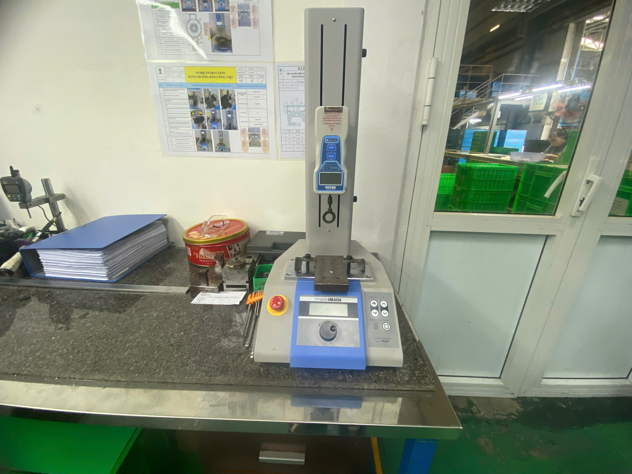
You need a calibrated bench Rockwell tester for routine checks, a Vickers micro-hardness tester for thin or coated parts, certified test blocks for daily verification, proper anvils and fixtures for odd geometries, and a portable tester for large parts that cannot reach the bench.

Think of the equipment list in three layers: the tester, the fixturing, and the verification tools. Miss any layer and your numbers drift.
The Core Equipment List
| Item | Purpose | Practical Tip |
|---|---|---|
| Bench Rockwell tester | Fast production and incoming checks | Keep multiple scales available (HRB, HRC, 30T) |
| Vickers/Knoop micro-hardness tester | Thin gauge, coatings, heat-affected zones | Budget time for mounting and polishing |
| Certified test blocks | Daily verification of the tester | Use blocks near your spec range, not just one |
| Flat and V-anvils | Stable, perpendicular support | Curved clips need matched fixturing |
| Portable Leeb/UCI tester | Large or awkward stamped assemblies | Treat readings as screening, not final data |
| Surface prep tools | Grinding, cleaning, deburring | Remove scale, oil, and zinc coating at the test spot |
Setup Details That Change Your Numbers
Fixturing is the silent error source. A Z-fold clip rocks on a flat anvil. The part flexes under load, and the tester reads the flex as extra depth. The result comes out soft even when the steel is fine. We ask suppliers to build simple nests for parts like our stepped brackets so the test point sits flat and perpendicular.
Surface condition is the second trap. Zinc plating, oxide scale, oil, and decarburized layers 7 all distort readings. Lightly grind the test spot on plated parts, or use micro-hardness through a cross-section when the coating itself is the feature under test.
Finally, verify daily. Run a certified test block at the start of each shift. Log the value. If the block reading drifts, stop and recalibrate before testing production parts. This five-minute habit protects every number that follows.
How Can I Verify My Supplier's Hardness Test Results Meet My Drawing Specifications?
A purchasing manager in the US once told me his biggest fear was not bad parts. It was good-looking reports on bad parts. Our answer to that fear is a layered verification approach, and it works because no single check carries all the weight.
Verify supplier hardness results by requiring raw data with test method, scale, load, and locations stated; cross-checking samples with independent or in-house testing; auditing calibration records and test blocks; and tracking hardness data on SPC charts across batches to catch drift early.

Here is the verification workflow we run on custom-part programs before anything ships to the US:
- Lock the spec at the drawing stage. Confirm the scale, standard, acceptance range, and test locations in writing. Ambiguity is where disputes are born.
- Demand complete reports, not summaries. A single "Pass" line means nothing. Ask for the tester model, calibration date, scale, load, number of readings, individual values, and locations. Five readings with the average and range tell you far more than one number.
- Witness or spot-check the test. During PPAP and pre-shipment inspection, our engineers watch the operator run parts and a certified block. We compare the block reading to its certificate on the spot.
- Retain and retest samples. Pull random parts from the shipped lot. Test them at a second location, whether an independent lab or your own bench. Compare against the supplier's data using the same scale.
- Chart the trend. Plot hardness values batch by batch on an SPC chart. Gradual drift often signals die wear, a coil change, or a heat-treatment furnace problem, long before parts fall out of spec.
What a Trustworthy Report Looks Like
A credible hardness report references the drawing revision. It names the standard, such as ASTM E18. It lists each reading and its location, ideally on a marked sketch of the part. It carries the tester's serial number and calibration due date. When any of those items are missing from a supplier's report, we send it back. In our experience, suppliers who resist providing raw data are the same ones who create rework and returns later. Insisting on transparent data upfront is cheaper than any claim process.
Conclusion
Wrong hardness data turns good stampings into rejected shipments. Match the method to the part, fix the standard on the drawing, maintain the equipment, and verify supplier data. We apply this workflow on every custom stamping project we manage.
Frequently Asked Questions
What Hardness Testing Methods Should I Use for Stamping Parts?
A few years back, our Vietnam office received a set of thin-gauge steel clips that kept failing Rockwell checks. The parts were fine. The test method was wrong. That project taught our team to match the method to the part first.
How Do I Choose the Right Hardness Standard for My Custom Stamped Components?
One trade-off comes up constantly in our co-development projects: buyers want a single hardness number on the drawing, but the right scale depends on the alloy and the process. Picking the wrong scale creates disputes later, so we settle it during the drawing review .
What Equipment Do I Need to Accurately Measure Hardness on Stamping Parts?
During a supplier audit in Vietnam last year, I saw a beautiful bench Rockwell tester with an expired calibration sticker and no test blocks in sight. The machine matters. The support system around it matters more.
Footnotes
1. Wikipedia details the Vickers hardness test and its diamond pyramid indenter geometry. ↩︎
2. ASTM E18 is the governing standard for Rockwell hardness testing referenced in credible reports. ↩︎
3. Cite the official standard defining Rockwell hardness test procedures. ↩︎
4. Reference the ISO standard governing Vickers hardness testing methods. ↩︎
5. AIAG defines the Production Part Approval Process used to lock hardness specs with customers. ↩︎
6. Background on bend radius explains why stamped parts work-harden unevenly at forming points. ↩︎
7. Background on decarburization explains why surface layers distort hardness readings on stamped parts. ↩︎