

We lost three weeks on a heavy equipment project last year because welded brackets arrived 1.8mm out of spec — and every downstream assembly step failed.
OEM procurement ensures welded part dimensional tolerances meet assembly requirements by defining functional tolerances through stack-up analysis, selecting appropriate ISO 13920 tolerance classes, mandating welding distortion control via fixtures and post-weld sizing, and validating compliance through multi-step inspection before shipment.
The gap between what a drawing says and what a weld shop delivers is where most assembly problems begin ISO 13920 tolerance classes 1. This article walks through how procurement teams can close that gap — from evaluating overseas suppliers to running on-site inspections — without blowing up the budget.
How can I evaluate if an overseas supplier has the technical capability to maintain my tight welding tolerances?
A client once asked us to audit a Vietnamese fabricator who claimed ±0.5mm capability on multi-joint weldments — but had no fixtures and only a tape measure on the shop floor.
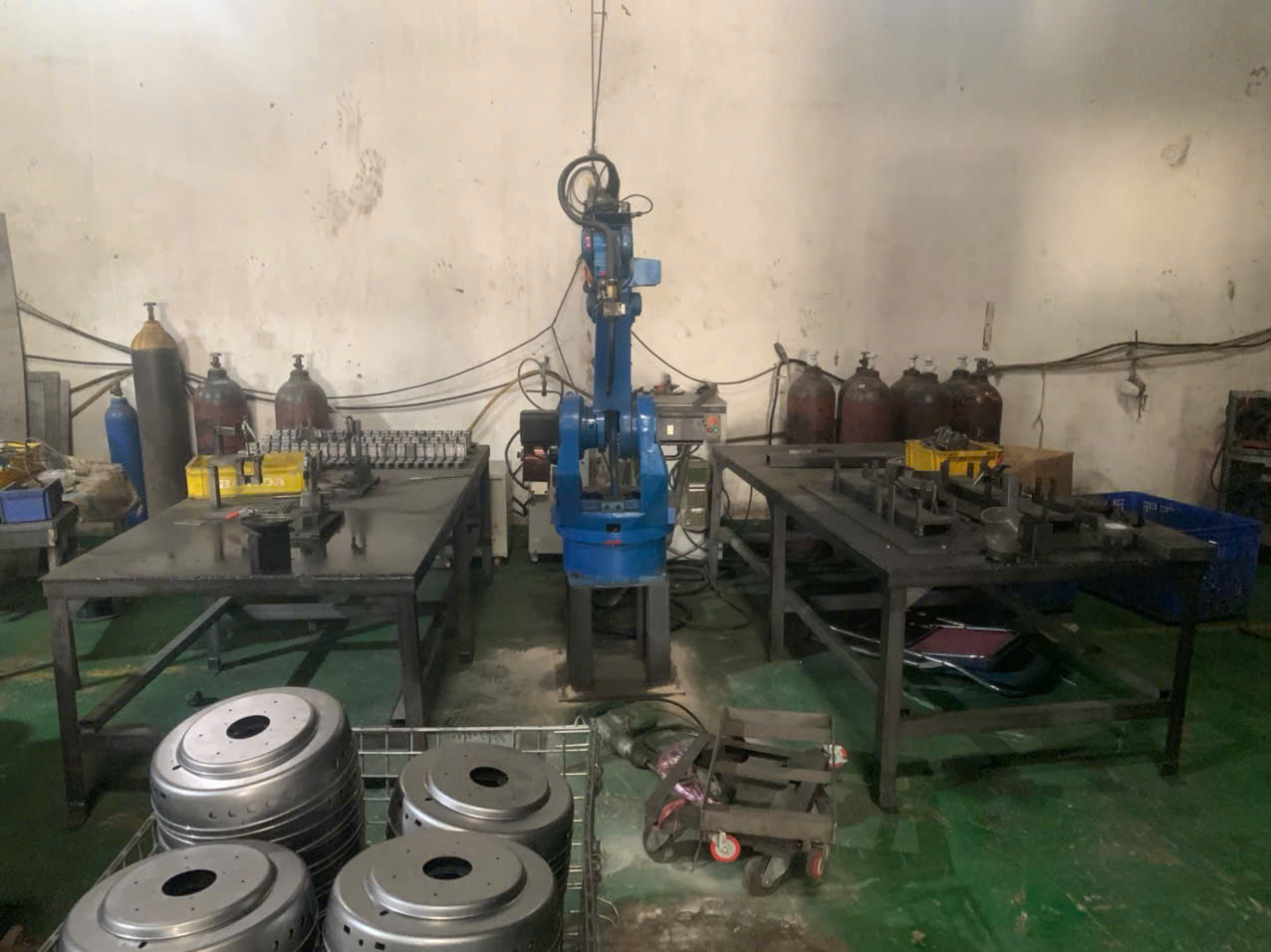
Evaluate an overseas welding supplier's tolerance capability by auditing their welding fixtures, metrology equipment, Welding Procedure Specifications (WPS), welder qualifications, and historical dimensional data — not just their verbal claims or sample parts.
Why Verbal Claims Are Not Enough
When our sourcing team visits a potential supplier in Vietnam or elsewhere in Asia, we follow a structured capability audit. A supplier can show you a perfect sample part. But that sample may have been hand-corrected, re-welded, or cherry-picked. What matters is whether their process can repeat that result across hundreds or thousands of parts.
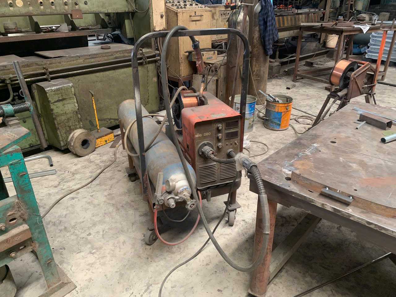
The first thing we look for is their welding fixture inventory. Welding Procedure Specifications (WPS) 2 Fixtures are the backbone of welding distortion control 3. Without dedicated fixtures, a welder relies on skill alone. Skill varies shift to shift, welder to welder. Fixtures do not.
The Capability Audit Checklist
Here is the framework our team uses during supplier qualification visits:
| Audit Area | What to Look For | Red Flag |
|---|---|---|
| Welding Fixtures | Dedicated fixtures for each part number, clamped and located from assembly datums | Universal or no fixtures; parts tack-welded freehand |
| Metrology Equipment | Vernier calipers (ISO 13385 4), dial gauges (ISO 463), CMM access | Only tape measures and steel rulers |
| WPS Documentation | Written Welding Procedure Specifications for each joint type and material | No WPS or generic documents not tied to specific parts |
| Welder Qualifications 5 | Certified welders with records tied to specific WPS | No certification records; welders assigned randomly |
| Historical Data | Dimensional inspection records from past production runs with Cpk data | No historical records; "we always pass inspection" |
| Post-Weld Capability | Sizing jigs, post-weld machining, or straightening equipment | No post-weld correction process |
Understanding Material-Specific Challenges
Not all metals behave the same under welding heat. Stainless steel, for example, has higher thermal expansion and lower thermal conductivity than mild steel. This means more distortion per weld. If your parts are stainless, the supplier needs to demonstrate specific experience managing that distortion. We always ask for material-specific examples during audits.
Metrology in Manufacturing Matters
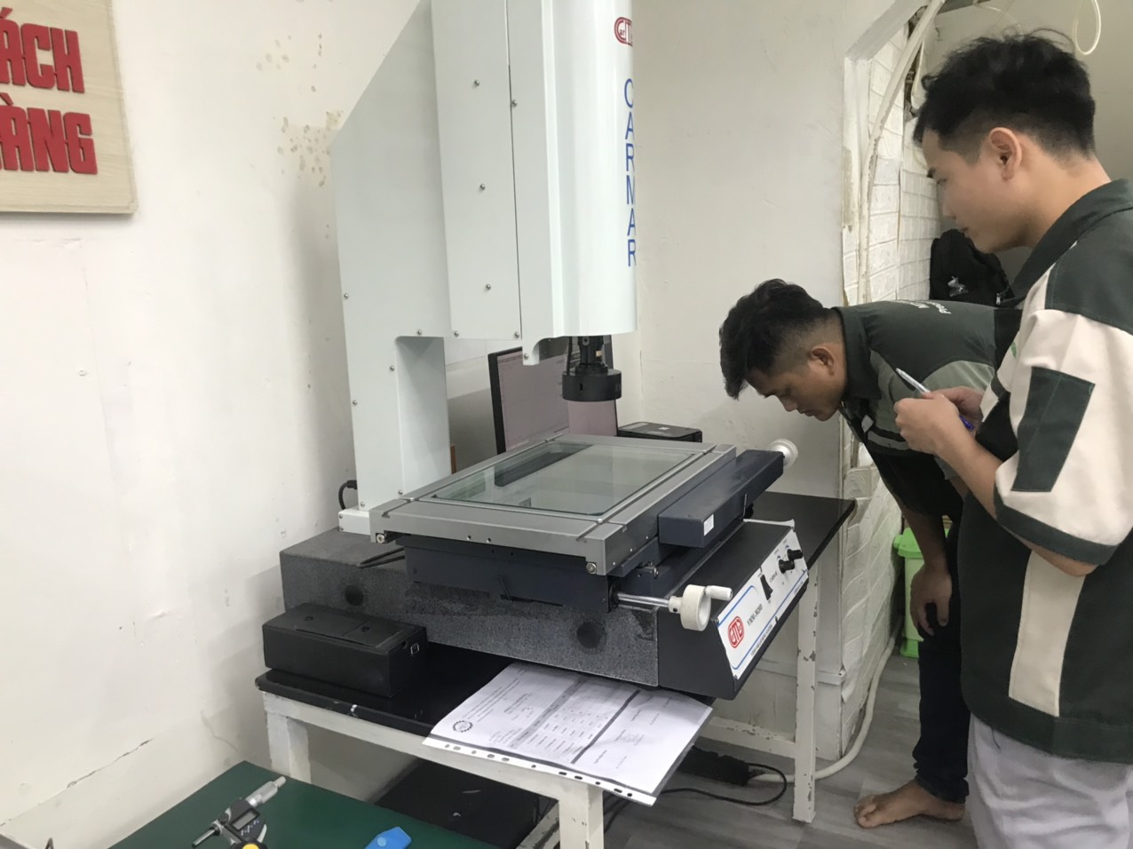
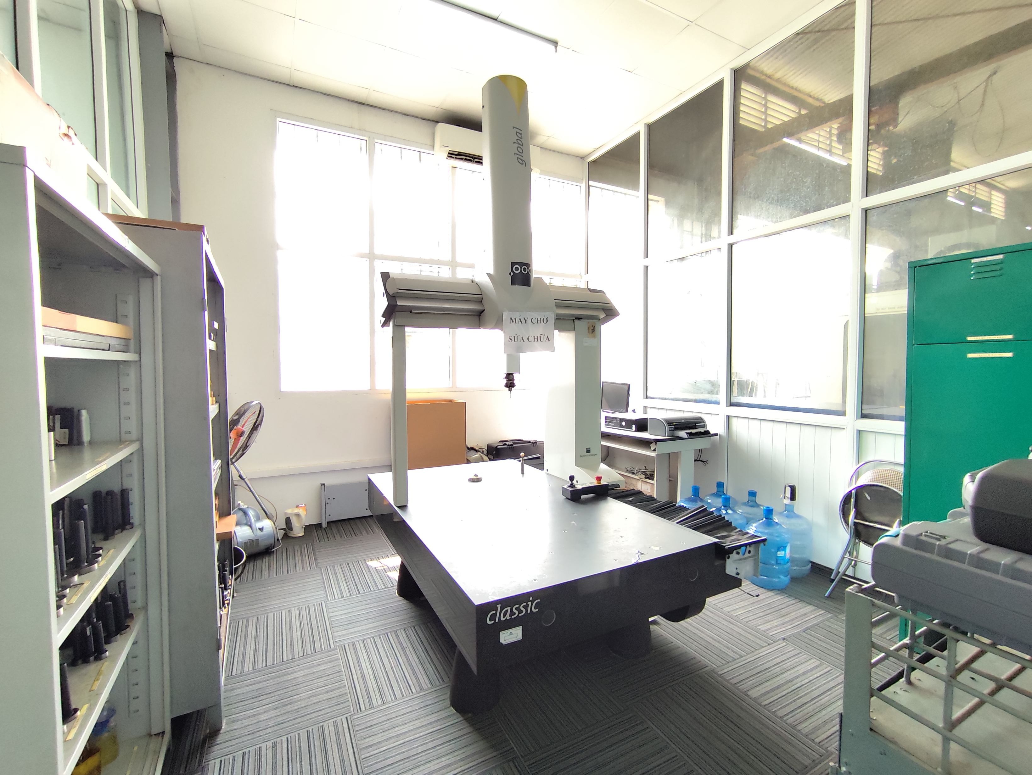
A supplier cannot hold tolerances they cannot measure. If a drawing calls for ±0.5mm on a 1200mm weldment, a tape measure is not sufficient. We require suppliers to have calibrated instruments appropriate to the tolerance class. For tighter work, we look for coordinate measuring machine (CMM) 6 access — either in-house or through a third-party lab. The measurement system must be suitable and accurate for the intended purpose, as ISO 13920:2023 requires.
We also check if they perform non-destructive testing (NDT) on critical welds. NDT validates weld integrity, but it also signals a quality-minded culture. A shop that invests in NDT typically invests in dimensional control too.
What steps should I include in my PPAP process to guarantee welded parts fit my final assembly?
One lesson we learned early in our PPAP work is that weldment submissions fail more often than machined parts — because teams underestimate how much tolerance stack-up grows with every welded joint.
Your PPAP process for welded parts should include tolerance stack-up analysis, fixture verification, multi-step dimensional reports at cutting/bending/welding stages, a measurement system analysis, and trial assembly verification to confirm parts fit the final assembly.
Tolerance Stack-Up Analysis Before PPAP Submission
Tolerance stack-up analysis 8 is the single most important pre-production step for welded assemblies. Every cut, bend, and weld adds variation. A part with four welded joints does not just carry the tolerance of the final weld — it carries the accumulated variation of every upstream step.
Consider a simple welded bracket assembly. If the base plate has a cutting tolerance of ±0.25mm, the bend adds ±0.25mm, and each weld joint adds ±0.5mm, the total worst-case stack-up can reach ±2.5mm or more. If your assembly only allows ±1.5mm at the mating interface, you have a problem — and you need to find it before PPAP, not after.
| PPAP Step | Purpose for Weldments | Deliverable |
|---|---|---|
| Design FMEA Review | Identify tolerance-sensitive features and distortion risk areas | Updated DFMEA with welding-specific failure modes |
| Tolerance Stack-Up Analysis | Calculate cumulative variation across all fabrication steps | Stack-up report showing worst-case and statistical results |
| Fixture Verification | Confirm welding fixtures locate from assembly datums | Photos, fixture drawings, and fixture qualification report |
| Multi-Step Dimensional Report | Verify dimensions after cutting, after bending, and after welding | Stage-gate inspection data for first articles |
| Measurement System Analysis | Confirm gauges and methods are adequate for required tolerances | GR&R study results |
| Trial Assembly | Physically fit parts into the assembly or mating fixture | Assembly fit report with photos and gap measurements |
Why Multi-Step Inspection Is Critical
In our experience managing supplier quality across Asia, we insist on checking critical features after each major fabrication step — not only at the end. If a laser-cut blank is already 0.3mm off on a hole location, no amount of careful welding will fix it. Catching errors early prevents compounding.
We define datums that survive each process step. For example, we locate holes from the formed face that will mate in the final assembly. This way, the datum is functionally meaningful, not just convenient for the fabricator.
Geometric Dimensioning and Tolerancing in PPAP
For complex weldments, we recommend using Geometric Dimensioning and Tolerancing (GD&T) 9 callouts on critical features. GD&T communicates not just size tolerances but also form, orientation, and position requirements. A flatness callout on a mounting surface, for instance, ensures the welded frame does not bow beyond acceptable limits — something a simple linear tolerance cannot capture.
The Trial Assembly Step
Many PPAP process 10es skip trial assembly for weldments. This is a mistake. We always recommend that the supplier build at least one complete assembly (or fit parts into a mating fixture) during PPAP. This reveals interference, gap, and alignment issues that dimensional reports alone may miss. Post-weld machining may be needed for critical mating surfaces, and the trial assembly confirms whether that step is adequate.
How do I ensure my critical drawing requirements for weldments are correctly interpreted by my manufacturing partner?
During a recent project involving heavy-duty mounting brackets, we discovered the supplier interpreted a symmetrical tolerance as a unilateral one — the result was 400 parts that mated on one side but interfered on the other.
Ensure correct drawing interpretation by using ISO 13920 tolerance class references, adding explicit GD&T callouts on critical features, holding a formal drawing review meeting before production, and maintaining a standards document that defines general tolerances and measurement methods.
The Drawing Is a Contract — Make It Unambiguous
A drawing is the legal definition of your part. But welded assemblies are harder to dimension clearly than machined parts. Heat-affected zones shift geometry. Weld beads add material. Surfaces warp. If the drawing does not account for these realities, the supplier will interpret gaps on their own — and their interpretation may not match yours.
ISO 13920:2023 as Your Baseline
ISO 13920:2023 specifies general tolerances for welded structures in four classes:
| Tolerance Class | Designation | Typical Application | Linear Tolerance (for 1000mm dimension) |
|---|---|---|---|
| Fine | A | Precision weldments, tight-fit assemblies | ±1mm |
| Mean | B | General structural assemblies | ±2mm |
| Approximate | C | Non-critical structures | ±3mm |
| Very Approximate | D | Rough fabrications | ±5mm |
By referencing a specific class (for example, ISO 13920-BE for good functional accuracy), you set a clear baseline. The supplier knows exactly what general tolerances apply to dimensions not individually toleranced on the drawing. This eliminates guesswork.
Calling Out Critical Features Separately
Where dimensions need tighter control than the general tolerance class allows, call them out directly on the drawing. For example, if a mounting hole pattern must be within ±0.3mm to align with a mating part, that tolerance appears right next to the dimension — not buried in a note block.
Non-symmetrical tolerances deserve special attention. If a slot must measure between 1000mm and 1004mm, dimension it as 1000 +0/+4. Do not rely on vague guidelines like "always design to upper limit." Specify the range clearly.
The Pre-Production Drawing Review
Before any metal is cut, we schedule a formal drawing review with the supplier's engineering team. This is not a courtesy call. It is a structured walkthrough of every critical dimension, datum, tolerance, weld symbol, and surface finish requirement. We ask the supplier to explain how they will achieve each callout. If they cannot articulate a plan, that is a signal to pause.
We also share a standards document. This document outlines our general tolerance expectations, references the applicable ISO standards, and lists the measurement tools and methods we expect. This document was developed by researching typical achievable tolerances and consulting with our supplier base — it reflects real-world capability, not theoretical perfection. For more detail on this topic, see our guide on how to communicate OEM tolerance requirements to sheet metal fabrication suppliers.
Welding Procedure Specifications Tie to Dimensions
Every welded joint on the drawing should have a corresponding Welding Procedure Specification. The WPS defines heat input, travel speed, filler material, and technique. These parameters directly affect distortion. If the drawing calls for a ±1mm tolerance on a frame dimension that spans four welded joints, the WPS must support that outcome. We verify this linkage during the drawing review.
What on-site inspection protocols can my sourcing team use to verify dimensional accuracy before shipment?
Last quarter, our Vietnam-based quality team caught a batch of welded frames where the vertical uprights were 1.2° out of plumb — within the supplier's internal "pass" criteria, but outside our customer's ±0.5° requirement. We caught it because we brought our own angle gauges.
Your sourcing team should use a multi-step inspection protocol: verify dimensions after each fabrication stage using calibrated instruments, check critical features against GD&T callouts, compare results to PPAP baseline data, and perform a final functional check against an assembly fixture or mating part.
Building the Inspection Protocol
An effective on-site inspection protocol for welded parts is more than a final check-the-box exercise. It is a staged verification process. Here is the protocol structure we use:
Stage 1: Incoming Material and Cutting
Verify raw material dimensions and certifications. Check cut blanks for length, width, and hole locations against drawing tolerances. Use vernier calipers (per ISO 13385) for hole diameters and tape measures for overall lengths. Record results.
Stage 2: Bending and Forming
After bending, check bend angles with calibrated protractors or angle gauges. Verify flange lengths and bend radii. Compare to drawing tolerances. If the part is already drifting, stop and correct before welding begins.
Stage 3: Post-Weld Dimensional Check
This is the most critical stage. After welding, measure all critical dimensions:
- Overall lengths, widths, and heights
- Hole-to-hole distances and patterns
- Flatness of mounting surfaces (use a straightedge and feeler gauges or a dial gauge per ISO 463)
- Angular alignment of uprights and brackets
- Weld bead locations and sizes
Compare every measurement to the PPAP baseline data. If a dimension has shifted beyond tolerance, the part must be reworked or rejected.
Stage 4: Post-Weld Correction Verification
If sizing jigs or post-weld machining are used, re-measure after correction. Confirm that the correction brought the part back within limits without introducing new problems (such as residual stress or surface damage).
Stage 5: Final Functional Check
Where possible, fit the part into an assembly fixture or mate it with a corresponding part. This is the ultimate test. Dimensional numbers on a report can look fine, but physical fit reveals issues that numbers sometimes hide — such as subtle twist or bow across a long weldment.
What Tools Should Your Team Carry?
| Instrument | Use Case | Applicable Standard |
|---|---|---|
| Vernier Caliper | Hole diameters, material thickness, small dimensions | ISO 13385-1 |
| Steel Tape Measure | Overall lengths and widths | ISO 13920:2023 reference |
| Dial Gauge | Flatness, runout, and surface deviation | ISO 463 |
| Protractor / Angle Gauge | Bend angles and angular alignment | ISO 13920:2023 reference |
| Feeler Gauges | Gap measurement for fit verification | General use |
| Straightedge (graduated steel) | Flatness and straightness checks | ISO 13920:2023 reference |
Documenting Everything
Every measurement must be recorded and tied to a specific part serial number, date, and inspector. We use standardized inspection reports that mirror the PPAP dimensional layout. This creates traceability. If a problem appears during assembly at the customer's facility, we can trace it back to the exact inspection data, the exact weld station, and the exact shift.
Our supplier quality management approach also includes requiring the supplier to maintain their own in-process inspection records. We audit those records during on-site visits. If the supplier's data and our data do not agree, that triggers a measurement system review.
When to Reject vs. When to Disposition
Not every out-of-tolerance dimension is a rejection. Some deviations are cosmetic. Others affect fit, form, or function. Our inspection protocol includes a classification system: critical, major, and minor. Critical dimensions that affect assembly fit or structural integrity get zero tolerance for deviation. Minor dimensions may be dispositioned on a case-by-case basis with customer approval.
This disciplined approach to quality control processes is what separates reliable supply chains from chaotic ones. It takes time to build. But once the protocol is in place, it prevents the rework, returns, and delays that cost far more than the inspection effort itself. If you are sourcing from Southeast Asia, understanding how to evaluate Vietnamese supplier capacity for OEM welding parts can further strengthen your supply chain.
Conclusion
Ensuring welded part dimensional tolerances meet assembly requirements demands active procurement management — from supplier audits and PPAP rigor to clear drawings and staged inspections. Get these right, and you eliminate the rework that kills schedules and budgets.
Frequently Asked Questions
How can I evaluate if an overseas supplier has the technical capability to maintain my tight welding tolerances?
A client once asked us to audit a Vietnamese fabricator who claimed ±0.5mm capability on multi-joint weldments — but had no fixtures and only a tape measure on the shop floor.
What steps should I include in my PPAP process to guarantee welded parts fit my final assembly?
One lesson we learned early in our PPAP work is that weldment submissions fail more often than machined parts — because teams underestimate how much tolerance stack-up grows with every welded joint.
How do I ensure my critical drawing requirements for weldments are correctly interpreted by my manufacturing partner?
During a recent project involving heavy-duty mounting brackets, we discovered the supplier interpreted a symmetrical tolerance as a unilateral one — the result was 400 parts that mated on one side but interfered on the other.
Footnotes
1. Details the ISO 13920 standard for general tolerances in welded constructions. ↩︎
2. Defines Welding Procedure Specifications as formal documents for welding procedures. ↩︎
3. Provides methods and techniques for controlling welding distortion in manufacturing. ↩︎
4. Specifies the design and metrological characteristics of calipers, including vernier calipers. ↩︎
5. Replaced with the American Welding Society (AWS) Certified Welder Program page, an authoritative source for welder qualifications. ↩︎
6. Describes CMMs as essential metrology equipment for accurate dimensional measurement. ↩︎
7. Introduces NDT methods for examining materials without causing damage. ↩︎
8. Explains the concept of tolerance stack-up analysis in mechanical engineering. ↩︎
9. Explains GD&T as a symbolic language for defining engineering tolerances on drawings. ↩︎
10. Outlines the Production Part Approval Process for ensuring consistent part quality. ↩︎