
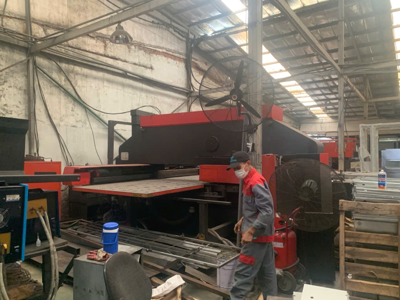
Key technical parameters on stamping parts drawings decide whether a project succeeds maximum material condition 1. I have watched a single misread callout on our production line scrap an entire tooling run.
To read key technical parameters on stamping parts drawings, check the title block first for part number, revision, units, and material. Then review dimensional tolerances, thickness callouts, surface finish symbols, GD&T controls, and datum references before quoting or approving any tooling.
That is the short answer. Now let me walk you through each parameter in the order I check them during a real drawing review.
What Are the Most Critical Dimensional Tolerances I Should Check on a Stamping Parts Drawing?
A few years back, our team in Vietnam caught a bracket drawing where a hole position tolerance was ten times tighter than the mating part needed. That one catch saved the client a costly progressive die rework.
The most critical tolerances on a stamping drawing are those tied to function: hole positions for fastener fit, bend angles affecting assembly, hole-to-edge distances, flatness callouts, and any dimension linked to a mating surface. Check these before general profile dimensions.

When I review a stamping drawing, I do not read every dimension with equal weight. That wastes time and misses risks. Instead, I sort dimensions into three groups: functional, cosmetic, and reference. Functional dimensions control fit and performance. Cosmetic dimensions affect appearance only. Reference dimensions are for information and carry no tolerance at all.
Start with the General Tolerance Block
Most stamping drawings only apply tight tolerances to a handful of features. Everything else falls under the general tolerance note, usually found near the title block. Confirm the standard being used. ISO 2768 2 and ASME-based general tolerances behave differently. If the drawing says nothing, stop and ask. We never quote a job with an ambiguous tolerance scheme, because ambiguity always turns into a dispute at final inspection.
Know Which Tolerances Drive Cost
Some tolerances are cheap to hold in stamping. Others are painful. Here is how I explain it to buyers:
| Tolerance Type | Typical Achievable Range | Cost Impact if Tightened |
|---|---|---|
| Punched hole diameter | ±0.05 to ±0.1 mm | Low to moderate |
| Hole-to-hole spacing (same station) | ±0.05 mm | Low |
| Hole-to-bend distance | ±0.2 to ±0.5 mm | High |
| Bend angle | ±1° | High below ±0.5° |
| Flatness on thin sheet | 0.1–0.5 mm typical | Very high if tighter |
Features formed in the same die station hold position well. Features that cross a bend line do not, because the material stretches and springs back. So when a client asks for ±0.05 mm across a 90-degree bend, I flag it immediately. Usually the design intent allows a looser value, and everyone saves money.
Watch for Tolerance Stack-Up
Chained dimensions accumulate error. If four dimensions in a row each carry ±0.1 mm, the end feature can drift ±0.4 mm. Good drawings dimension critical features from a single datum instead. If I see a long dimension chain feeding a critical hole, I raise it with the client before tooling design begins, not after.
How Do I Interpret Material Specifications and Thickness Callouts on a Stamping Drawing?
One trade-off we weigh constantly when sourcing custom parts across Vietnam and Taiwan is material equivalence. A U.S. drawing may call for an ASTM grade, while the local mill supplies a JIS equivalent. Reading that callout correctly matters.
Interpret material callouts by identifying three elements: the material standard and grade, the temper or hardness condition, and the nominal thickness with its tolerance. Also check for grain direction arrows, since bending tight radii along the grain increases cracking risk.

The material line in the title block looks simple, but it hides most of the manufacturability story. Almost every geometry rule in stamping is expressed as a multiple of thickness. Minimum bend radius, hole-to-edge distance, minimum web width — all of them scale with the letter T. So before I judge any feature, I lock down what T actually is.
Break the Callout into Parts
A typical callout might read: SPCC, t=1.2 mm, or 5052-H32, 0.062 in. Each piece tells you something different:
| Callout Element | What It Tells You | Why It Matters |
|---|---|---|
| Standard and grade | Chemistry and mechanical properties | Determines formability and strength |
| Temper (e.g., H32, 1/4 hard) | Work-hardening state | Affects springback and minimum bend radius |
| Thickness | Nominal stock gauge | Baseline for all T-multiple design rules |
| Thickness tolerance | Allowed sheet variation | Impacts flatness, fit, and forming force |
| Grain direction | Required coil orientation | Reduces cracking on tight bends |
Temper Changes Everything
The same alloy behaves very differently at different tempers. A fully annealed aluminum bends easily at a 1T radius. The same alloy in a hard temper may crack at 2T. On one project through our Vietnam office, a drawing specified a hard-temper stainless with a bend radius equal to the thickness. Our engineers flagged it, the client relaxed the radius to 1.5T, and the parts formed cleanly on the first tooling trial. Getting it right the first time started with reading that temper code.
Do Not Ignore Thickness Tolerance
Sheet stock varies from the mill. If the drawing demands 1.0 mm ±0.02 mm but the material standard allows ±0.05 mm, the drawing conflicts with reality. I always cross-check the thickness tolerance against what the specified standard actually permits. Also confirm units. A drawing mixing millimeters and gauge numbers invites errors, and gauge values differ between steel, stainless, and aluminum.
Grain Direction Arrows
Some drawings include an arrow showing rolling direction. This tells the stamper how to orient the coil. Bends made parallel to the grain crack more easily on tight radii. If a part has tight bends in two perpendicular directions, that arrow becomes a real engineering constraint, not decoration.
What Surface Finish and Coating Symbols Do I Need to Understand Before Approving a Stamping Design?
A buyer once emailed me late on a Friday asking why his zinc-plated brackets would not fit their mating slots. The answer sat on the drawing all along: the plating thickness was never subtracted from the stamped dimensions.
Before approving a stamping design, understand surface roughness symbols with Ra values, plating callouts with coating type and thickness, burr direction notes, and edge condition requirements. Confirm whether dimensions apply before or after coating, since plating adds measurable thickness.
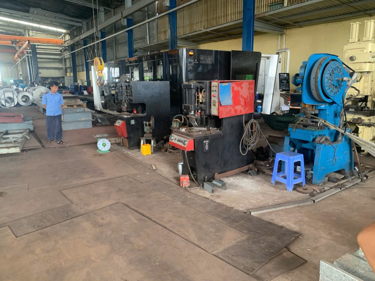
Surface requirements live in three places on a drawing: the finish symbols on specific surfaces, the notes block, and sometimes the title block. I check all three, because they must agree with each other.
Reading Roughness Symbols
The checkmark-style surface texture symbol carries an Ra value in micrometers or microinches. For stamped parts, roughness usually matters on sealing faces, electrical contact surfaces, or cosmetic panels. Most stamped surfaces simply inherit the mill finish of the sheet, so a roughness callout on a non-functional face is worth questioning. It may add polishing cost for no benefit.
Common Coating Callouts and What They Change
| Callout Example | Meaning | Practical Impact |
|---|---|---|
| Zinc plate, 5–8 µm, clear chromate | Electroplated zinc with passivation | Adds thickness; hydrogen embrittlement 3 risk on hard steels |
| Passivate per spec | Stainless steel passivation | No dimensional change; improves corrosion resistance |
| Powder coat, 60–100 µm | Thick organic coating | Significant thickness gain; may fill small holes |
| E-coat | Electrophoretic paint 4 | Uniform thin coverage, including recesses |
| Break all edges / deburr | Edge condition requirement | Adds a secondary operation and cost |
When we run PPAP submissions 5 for U.S. clients, coating thickness is measured and documented, so the drawing must state whether hole diameters and slot widths apply pre-plate or post-plate. A 6 µm zinc layer shrinks a hole by roughly 12 µm on diameter. On a precision fastener hole, that matters.
Burr Direction Is a Finish Requirement Too
Every punched edge has a burr side. Good drawings mark burr direction with a note or symbol, especially when the part touches wiring, gaskets, or human hands. Burr height is often limited to around 10% of material thickness as a working guideline. If the drawing says nothing about burrs, I ask the client which face mates with what. That five-minute question prevents assembly problems and safety complaints later. Masking requirements matter as well. If a ground contact must stay unplated, the drawing needs an explicit masking note, or the plater will coat everything.
How Can I Identify GD&T Symbols and Datum References to Avoid Miscommunication with My Stamping Supplier?
During a supplier audit near Ho Chi Minh City, I asked the QC lead how he fixtured a Z-shaped clip for inspection. His answer did not match the drawing's datum scheme, and that mismatch explained months of disputed measurement reports.
Identify GD&T by finding the datum reference frame first — datums A, B, and C marked on physical surfaces — then reading each feature control frame left to right: symbol, tolerance zone, modifiers, and datum sequence. The datums define exactly how the part is fixtured and measured.

GD&T 6 exists to remove argument. A coordinate dimension can be measured many ways. A feature control frame with datums can be measured only one way. For stamped parts, this matters even more than for machined parts, because formed sheet metal flexes. Without a defined datum scheme, two labs measuring the same bracket can honestly report different numbers.
The Symbols You Will Actually See on Stamping Drawings
You do not need the full GD&T standard memorized. On stamping drawings, a handful of symbols do most of the work:
- Flatness — controls warp on a surface without any datum. Common on mounting tabs. Be careful: very tight flatness on thin sheet is one of the most expensive requirements to hold.
- True position — locates holes relative to datums. This is the workhorse symbol for stamped brackets with fastener holes.
- Perpendicularity — controls a flange angle relative to a datum face. Springback makes this a genuine process challenge.
- Parallelism — often applied between opposing flanges or between a tab and the base.
- Profile of a surface — increasingly used to control complex trimmed edges with one callout.
Reading the Datum Scheme Like a Fixture Plan
Datum A is usually the largest mounting face. Datum B is often a primary hole. Datum C stops rotation. When I see the datum frame, I mentally build the inspection fixture: the part sits on A, a pin engages B, and a second pin or edge stop sets C. If the datums sit on surfaces that deform during forming, or on tiny tabs that cannot locate the part repeatably, I flag it. A datum scheme that cannot be fixtured is a drawing problem, not a supplier problem.
Modifiers Change the Money
The circled M, maximum material condition 7, gives bonus tolerance as a hole grows larger. On high-volume stamped parts, MMC callouts allow functional gauging with simple go/no-go fixtures instead of CMM time. That lowers inspection cost per piece. When our process control team sets up SPC for a client's critical-to-quality features statistical process control 8, the drawing’s GD&T tells us exactly which characteristics need monitoring and which can rely on tooling stability. If a drawing marks CTQ or key characteristic symbols, expect those features to need documented capability data, not just a passing first article.
Conclusion
Misread drawings cause scrap, delays, and disputes. Check the title block, tolerances, material, finish, and datums before release, and your stamping parts drawings become a shared contract, not a gamble.
Frequently Asked Questions
What Are the Most Critical Dimensional Tolerances I Should Check on a Stamping Parts Drawing?
A few years back, our team in Vietnam caught a bracket drawing where a hole position tolerance was ten times tighter than the mating part needed. That one catch saved the client a costly progressive die rework.
How Do I Interpret Material Specifications and Thickness Callouts on a Stamping Drawing?
One trade-off we weigh constantly when sourcing custom parts across Vietnam and Taiwan is material equivalence. A U.S. drawing may call for an ASTM grade, while the local mill supplies a JIS equivalent. Reading that callout correctly matters.
What Surface Finish and Coating Symbols Do I Need to Understand Before Approving a Stamping Design?
A buyer once emailed me late on a Friday asking why his zinc-plated brackets would not fit their mating slots. The answer sat on the drawing all along: the plating thickness was never subtracted from the stamped dimensions.
Footnotes
1. Maximum material condition is a core GD&T modifier defined under the ASME Y14.5 standard. ↩︎
2. ISO general tolerance standard directly referenced for stamping drawing tolerances ↩︎
3. Technical background on plating risk mentioned for hard steel coatings ↩︎
4. Background on E-coat process mentioned as a coating callout type ↩︎
5.