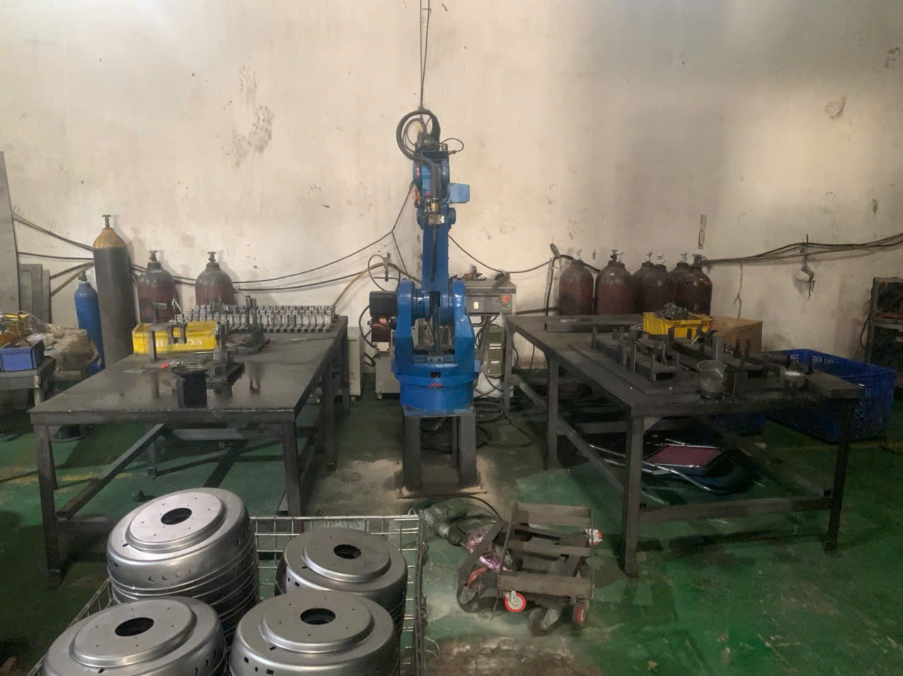

Testing the fatigue life of stamping parts saved one of our bracket projects from field failure. A part can pass every static check and still crack after thousands of load cycles.
To test the fatigue life of stamping parts, define the real service loads, apply controlled cyclic loading to coupons or full parts on servo-hydraulic or resonance machines, record cycles to failure, build an S-N curve, and validate results against standards like ASTM E466 or ISO 12106.
That is the short answer. But a fatigue test only predicts real life if it is designed well. Let me walk you through how we approach it, step by step.
What Methods Can I Use to Evaluate the Fatigue Life of My Stamping Parts?
A few years back, our engineers in Vietnam traced a cracked mounting clip to a shear edge, not the base material. That case taught us why test method selection matters so much.
You can evaluate the fatigue life of stamping parts using constant-amplitude testing to build S-N curves, load-step or block-program testing for variable service loads, strain-controlled testing for formed zones with local yielding, and full-component testing to capture real geometry and stress concentrations.
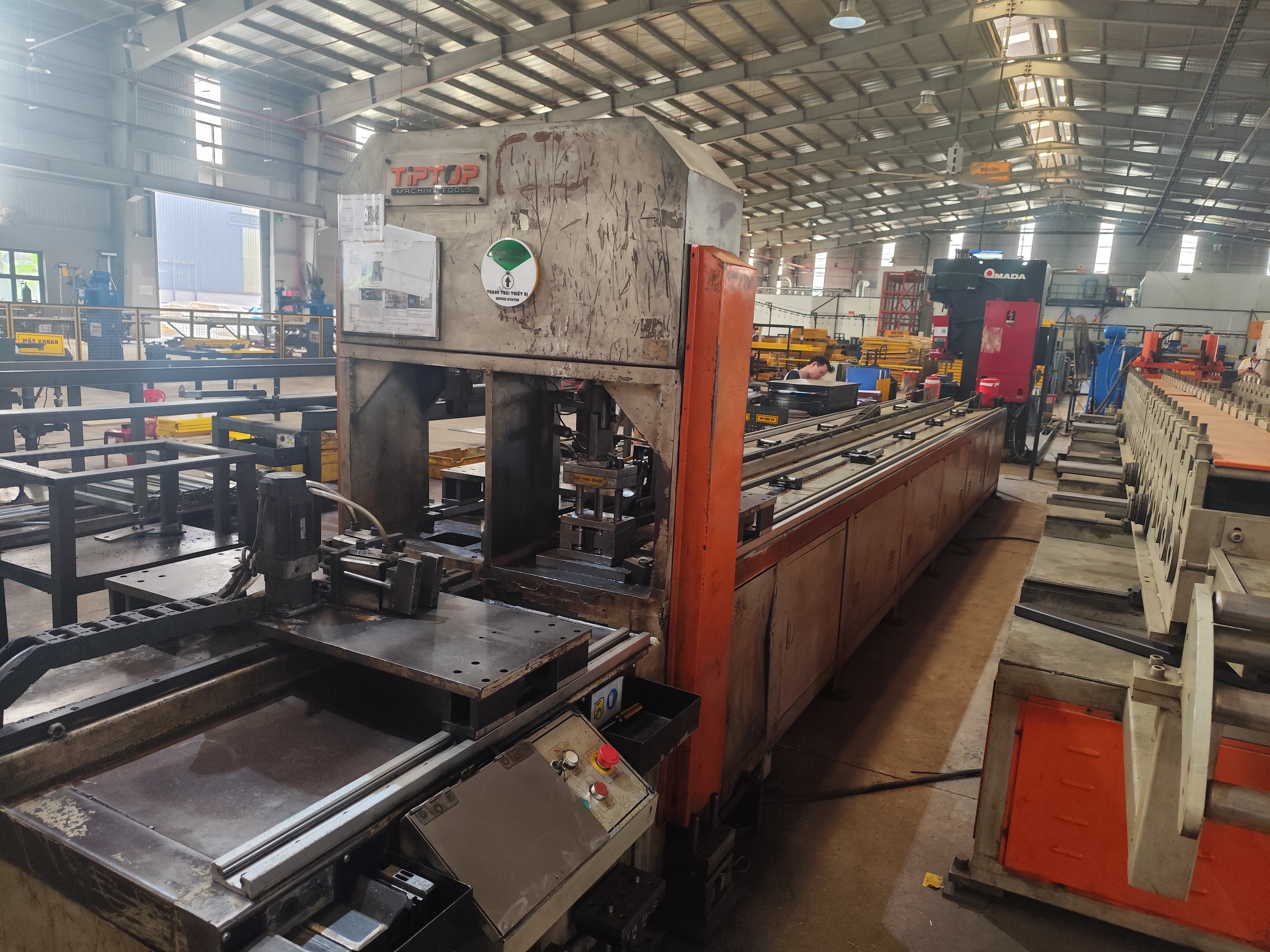
There are two levels of fatigue evaluation, and most solid programs use both. The first level is coupon testing 1. You cut standardized specimens from the stamped sheet or from formed blanks. This isolates the material behavior and the process effects, such as work hardening from forming. The second level is component testing 2. You cycle the actual stamped part under loads that mimic service. This captures bend radii, punched holes, and real boundary conditions that a flat coupon cannot show.
The Main Test Methods Compared
| Method | How It Works | Best For | Limitation |
|---|---|---|---|
| Constant-amplitude | Fixed stress amplitude until failure or runout | Building classic S-N (Wöhler) curves | Ignores variable real-world loads |
| Load-step / block-program | Applies blocks of different stress levels | Parts with varying service histories | More complex setup and analysis |
| Strain-controlled | Controls local strain, not load | Formed zones with plastic deformation | Slower; needs extensometry |
| Accelerated testing | Raises stress or frequency to shorten time | Fast comparisons between variants | Can change the failure mechanism |
| Full-component testing | Cycles the real stamped part | Final design validation | Costly; needs custom fixtures |
In my experience, the smartest sequence is this: run coupon tests early to compare materials and edge conditions cheaply, then confirm the final design with component tests. High-cycle fatigue work usually targets lives above ten thousand cycles, and many practical programs validate around one million cycles or more. If your part sees vibration, impacts, or mixed loading in service, add a variable-amplitude block program. It costs more, but it predicts field life far better than a single-amplitude test alone.
How Do I Choose the Right Fatigue Testing Standards for My Custom Stamped Components?
One of our U.S. purchasing clients once sent us three different fatigue specs for the same bracket family. Sorting that out pushed us to build a simple standard-selection logic we still use today.
Choose fatigue testing standards based on load type and market: use ASTM E466 for constant-amplitude axial force testing in North America, ISO 12106 for strain-controlled testing, and GB/T 3075 for Asian-sourced parts, then align stress ratio, specimen orientation, and runout criteria with your service conditions.

The standard you pick sets the rules of the game. It defines specimen geometry, loading control, frequency limits, and how you report runouts. Picking the wrong one creates data your customer cannot compare against their design allowables.
Match the Standard to the Question You Are Asking
Start with the failure mode you expect. If your stamped bracket sees mostly elastic, high-cycle loading, a force-controlled standard like ASTM E466 fits well. If the critical zone is a tight bend with local plastic strain, a strain-controlled standard like ISO 12106 is the better tool. For parts we source across Asia for U.S. buyers, we often run to the ASTM method but document equivalence to the local standard so both sides accept the data.
Key Parameters You Must Fix Before Testing
| Parameter | Why It Matters | Typical Practice for Stamped Sheet |
|---|---|---|
| Stress ratio (R) | Mean stress shifts fatigue life strongly | R = 0.1 is common to avoid buckling thin sheet in compression |
| Specimen orientation | Rolling direction creates anisotropy | Cut specimens matching the forming direction of the part |
| Runout definition | Sets when a test stops without failure | Often 10⁶ to 10⁷ cycles depending on application |
| Repetitions per level | Fatigue scatter is large | Multiple specimens per stress level to quantify variation |
| Surface condition | Polished data overstates real life | Test as-stamped surfaces, document roughness |
Also decide early between infinite-life and finite-life design. Some components must stay below an endurance-type threshold forever. Many stamped parts, though, are validated for a defined finite life because local damage and scatter make true infinite-life claims risky. Write that target life into the test plan before the first cycle runs. When service loads are not fully reversed, apply a mean-stress correction such as a Gerber-type model so the standard data maps onto your actual duty cycle.
What Equipment Do I Need to Accurately Test Fatigue Performance in Stamping Parts?
Fixture design is the trade-off I weigh most carefully when we set up component tests for clients. A perfect machine with a sloppy fixture still produces misleading numbers.
Accurate fatigue testing of stamping parts requires a servo-hydraulic or resonance testing machine, calibrated load cells, custom fixtures that replicate real mounting conditions, extensometers or strain gauges for local strain, and crack-detection tools such as microscopes or compliance monitoring.
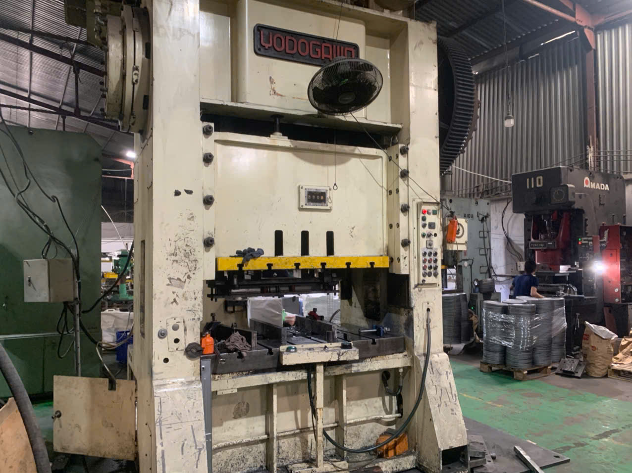
Let me break the equipment down by function, because each piece answers a different question in the test chain.
Load Application
Servo-hydraulic machines are the workhorse. They handle tension-compression, bending, and variable-amplitude spectra with precise control. Resonance machines cycle much faster, which cuts test time for long high-cycle programs, but they only run near a fixed frequency and simple waveforms. For small stamped clips and brackets like the ones we manage for cabinetry and machinery clients, electrodynamic shakers also work well for vibration-driven fatigue.
Measurement and Monitoring
You need a calibrated load cell in the load path and a way to see what the critical zone is doing. Strain gauges 3 bonded near a punched hole or bend radius confirm that your fixture creates the intended local stress. Without that check, your S-N data may describe the fixture, not the part.
The Equipment Stack at a Glance
| Equipment | Role in the Test | Notes for Stamped Parts |
|---|---|---|
| Servo-hydraulic frame | Applies controlled cyclic loads | Flexible waveforms; standard choice |
| Resonance machine | High-frequency cycling | Fast, but limited load spectra |
| Custom fixtures | Replicate real boundary conditions | Must match screw holes and mounting flanges |
| Strain gauges / extensometer | Verify local strain at critical zones | Place at bends, holes, shear edges |
| Optical microscope / dye penetrant | Detect crack initiation | Watch shear-affected edges first |
| Data acquisition system | Records cycles, load, displacement | Enables rainflow counting for variable loads |
One practical note from our supplier audits: the fixture must grip the part the way the application does. A zigzag-profile bracket loaded through its actual oval fastening holes behaves very differently than one clamped rigidly across its flanges. Before committing to a full program, run a short shakedown test and inspect where the crack starts. If it initiates somewhere the field parts never crack, fix the setup before generating data. Finally, pair the physical rig with FEA. Simulation locates the high-stress regions finite element analysis 4 so you instrument the right spots, and the test data then validates the model for future design iterations.
How Can I Ensure My Supplier's Fatigue Testing Data Meets My Quality Requirements?
A lesson we learned early in our sourcing work: a beautiful S-N curve 5 in a supplier report means little if the specimens were polished while production parts ship with raw sheared edges.
Verify supplier fatigue data by confirming the test standard and stress ratio used, checking that specimens match production surface finish, edge condition, and forming direction, requiring multiple repetitions per stress level with statistical treatment, and auditing equipment calibration records and raw cycle-count data.

Fatigue data is easy to make look good and hard to make honest. When we audit stamping suppliers across Vietnam, Taiwan, and India for our U.S. clients, we run through a fixed checklist before accepting any fatigue report into a PPAP package 6.
The Audit Checklist We Use
- Confirm the standard, control mode, stress ratio, and runout criterion are stated and match the agreed test plan.
- Check specimen sourcing. Were coupons cut from actual production sheet, in the correct orientation to the rolling direction?
- Verify surface and edge condition. As-stamped edges, coatings, and roughness must match production, because polished-specimen data overstates real part life.
- Look for repetitions. A single specimen per stress level tells you almost nothing; fatigue scatter demands multiple tests and, ideally, Weibull 7 or similar statistical treatment.
- Ask for raw data, not just the curve. Cycle counts, failure locations, and photos of fracture surfaces should back up every plotted point.
- Review calibration certificates for the load cell and frame, and confirm the test lab's accreditation where relevant.
Why Process Variables Belong in the Report
Stamping process settings shift fatigue life even when material and geometry are identical. Die clearance, punch speed, and blank-holder force change residual stresses and the depth of the shear fracture zone. Micro-cracks from hot stamping or coating deformation cut life further. So a credible report ties the tested parts to specific process parameters and a production date. If tooling wears or parameters drift later, the old data may no longer represent current parts. That is why we tie fatigue validation into ongoing process control, not just a one-time approval. It is also why we insist on retest triggers: a die refurbishment, a material lot change, or a coating change should each reopen the fatigue question.
Conclusion
Fatigue failures are silent until they are expensive. Test the fatigue life of stamping parts with realistic loads, matched specimens, proper standards, and audited data—then keep validating as production evolves.
Frequently Asked Questions
What Methods Can I Use to Evaluate the Fatigue Life of My Stamping Parts?
A few years back, our engineers in Vietnam traced a cracked mounting clip to a shear edge, not the base material. That case taught us why test method selection matters so much.
How Do I Choose the Right Fatigue Testing Standards for My Custom Stamped Components?
One of our U.S. purchasing clients once sent us three different fatigue specs for the same bracket family. Sorting that out pushed us to build a simple standard-selection logic we still use today.
What Equipment Do I Need to Accurately Test Fatigue Performance in Stamping Parts?
Fixture design is the trade-off I weigh most carefully when we set up component tests for clients. A perfect machine with a sloppy fixture still produces misleading numbers.
Footnotes
1. ASTM publishes standardized procedures for coupon-based fatigue testing referenced throughout the article. ↩︎
2. Background reference on fatigue mechanisms relevant to full-component validation testing. ↩︎
3. Explains the measurement device used for local strain verification. ↩︎
4. Background on FEA simulation paired with physical fatigue testing. ↩︎
5. Background concept explaining fatigue life and S-N curves used throughout. ↩︎
6. Links to ISO body relevant to production part approval quality standards. ↩︎
7. Statistical distribution referenced for treating fatigue scatter data. ↩︎