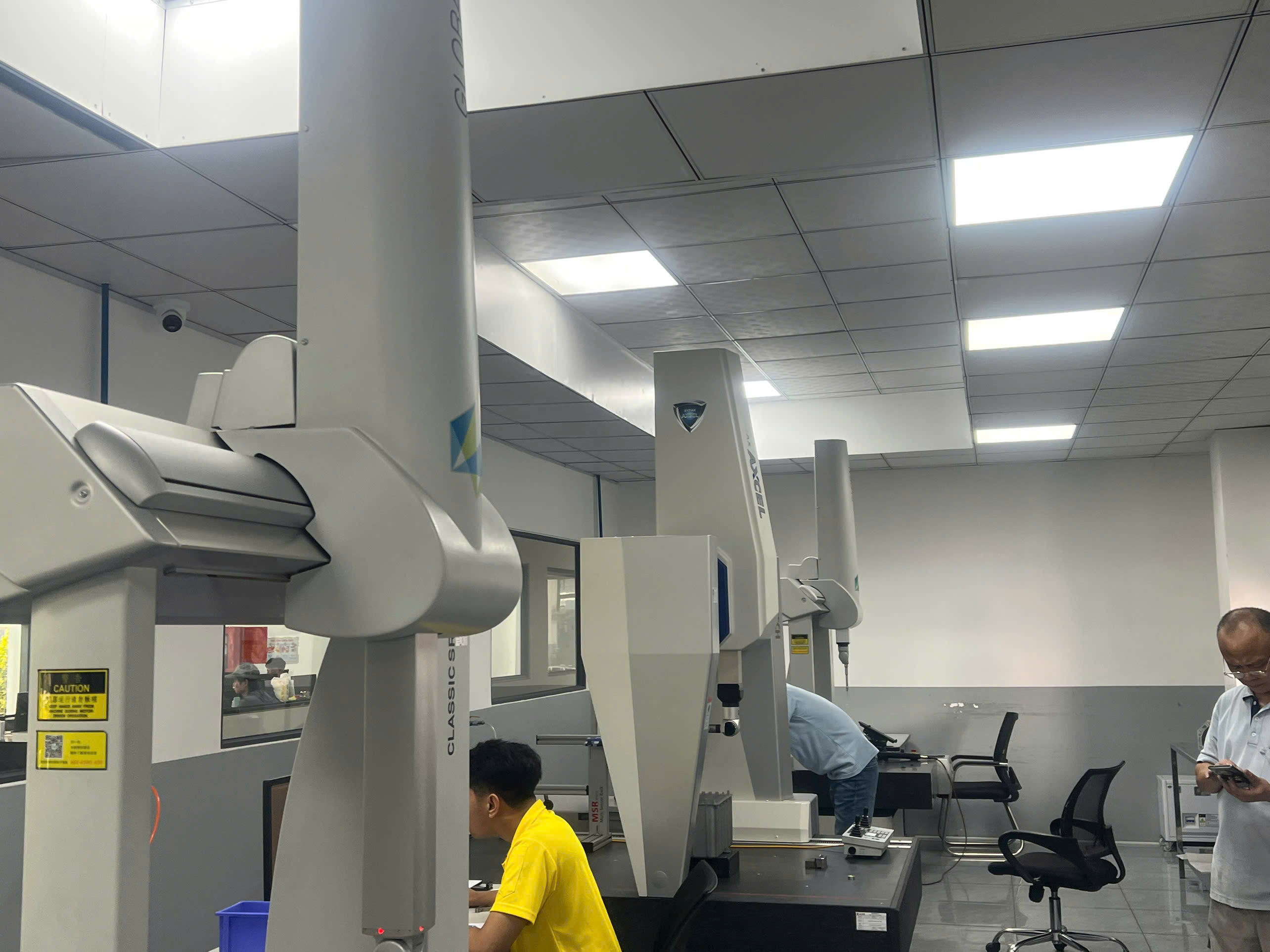
How Do You Set Up CMM Dimensional Inspection for Stamped Parts?
Setting up a CMM for part inspection requires confirming the latest drawing revision, verifying machine calibration, and stabilizing temperature to 20 ±1 °C. Parts are cleaned, mounted without distortion on datum locating points, aligned to the datum reference frame, and dry-run for collision simulation before final coordinate measurement and raw data archiving.
Key Takeaways
- Mount stamped parts in distortion-free fixtures aligned to drawing datums before running CMM dimensional inspection.
- Select the shortest, stiffest stylus possible to minimize bending error when probing complex sheet metal features.
- Resolve CMM measurement discrepancies between labs by standardizing datum alignment, fixturing methods, and probe settings.
- Track CMM data trends with SPC charts to detect die wear early and feed point cloud maps into tooling springback compensation.
Skipping setup steps introduces corrupted inspection data on sheet metal components. Setup discipline ensures that software nominals match current engineering specifications.
Program choices dictate measurement quality. Selecting a machine measuring range roughly double the largest part size leaves room for fixtures and probe moves, while point density should be higher on profiles than on simple holes.
- Confirm drawing revision and sync tolerance tables with the CMM program.
- Verify machine repeatability daily using a reference artifact.
- Stabilize environment to 20 ±1 °C and allow stamped parts to acclimate.
- Clean and deburr parts to prevent contact point shifts.
- Fixture without forcing thin walls flat using engineered locating points.
- Align coordinate systems strictly to drawing datum reference frames.
- Program probe paths and run a dry-run collision simulation.
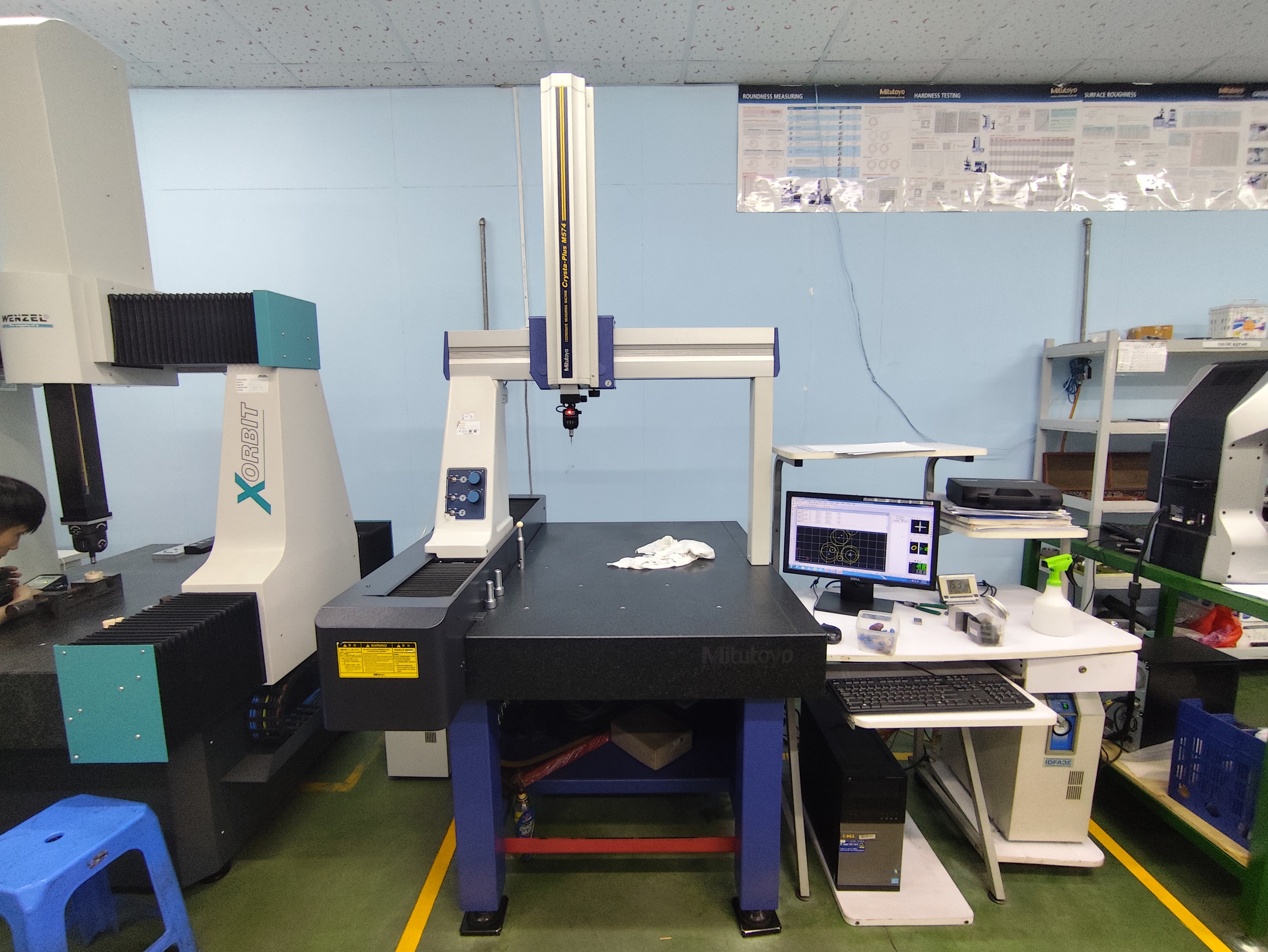
Which Probes and Fixtures Work Best for CMM Part Inspection?
Selecting probes for CMM dimensional inspection requires matching sensor types to feature geometries. Tactile touch probes work best for discrete holes, scanning probes measure flatness and profile springback, and non-contact optical sensors suit reflective finishes. Fixtures must support parts at 3-2-1 datum points without clamping thin metal flat.
Every probing plan balances reach against rigidity. Longer styli reach deep features but flex, introducing dynamic measurement error. Using the shortest, stiffest stylus with a carbide stem minimizes bending during inspection routines.
Over-clamping thin sheet metal deforms parts, causing the CMM to measure fixture distortion rather than true geometry. Dedicated checking nests provide repeatable loading without bending flexible walls out of their natural or specified assembly state.
- Touch-trigger probes: Ideal for hole positions, diameters, and edge points.
- Scanning probes: Best for surface flatness, bend radii, and springback contours.
- Optical sensors: Best for reflective finishes and delicate thin sections.
- Stylus selection: Use shortest possible length and select ball size per feature.
- Fixturing: Support parts at datum locations using light clamping forces.
Why Do Supplier and In-House CMM Inspection Results Differ?
Discrepancies in CMM dimensional inspection between labs usually stem from differing datum alignments, clamping force variations, thermal environment shifts, or stylus setups—not machine calibration failure. Flexible sheet metal allows small process differences to alter measurements. Conducting a structured correlation study resolves gaps by aligning both labs to one documented inspection method.
Calibration only controls machine accuracy; it cannot prevent measurement shifts caused by improper datum reference frame selection or free-state versus restrained fixturing conditions.
To resolve conflicting reports, labs should measure identical serialized parts, record thermal conditions and software parameters, compare results feature-by-feature, and document a unified inspection method inside the quality control plan.
- Datum alignment differences create large shifts across all position measurements.
- Clamping and fixturing variations alter thin, compliant sheet metal geometries.
- Evaluating free-state versus restrained requirements prevents drawing misinterpretations.
- Thermal drift alters dimensions if part acclimation time is omitted.
- Drawing revision mismatches completely invalidate comparative CMM reports.

How Can CMM Part Inspection Data Prevent Tooling Rework?
CMM dimensional inspection data prevents rework by serving as evidence for First Article Inspection and PPAP release gates. Plotting dimensional trends on SPC charts reveals punch wear and die clearance expansion before parts exceed tolerance. Additionally, scanned point clouds yield color-coded deviation maps used to adjust tooling for springback compensation.
Static pass/fail checks miss gradual dimensional drift across production lots. Monitoring key features with statistical process control charts enables proactive die maintenance before non-conforming parts are produced.
Feeding scanned CMM deviation maps back to tooling engineers allows precise die modification, reducing trial iterations needed to achieve nominal part dimensions.
- Gate production release using formal FAI and PPAP dimensional evidence.
- Track hole diameters, trim edges, and bend angles on SPC charts to detect die wear.
- Supply scanned point cloud deviation maps to tooling engineers for springback adjustments.
- Pair numeric measurement reports with visual color-coded maps for press operators.
Engineering & Production Specification Matrix
| Process Parameter | Prototype / Short-Run Standard | Production Progressive / Hard-Tool Standard | Verification Method |
|---|---|---|---|
| Linear Dimensional Tolerance | ±0.10 mm to ±0.15 mm (ISO 2768-m) | ±0.03 mm to ±0.08 mm (ISO 2768-f) | Optical 2D/3D CMM & Go/No-Go Check Fixtures |
| Edge Burr Height Limit | ≤ 10% of material thickness | ≤ 5%–8% of material thickness | Digital Micrometer & Cross-Section Audit |
| Material & Coating Traceability | Mill Test Certificate (EN 10204 3.1) | Heat-lot MTC + RoHS/REACH + ASTM B117 Salt-Spray | Spectrometer (OES) & XRF Screening |
| Standard Tooling & Lead Time | Laser + CNC Press Brake (5–10 days) | Progressive / Transfer Die (3–5 weeks T1) | First Article Inspection (FAI) & CPK ≥ 1.33 |
Frequently Asked Questions
What causes false dimensional errors during CMM inspection of thin sheet metal?
False errors occur when parts are over-clamped, measured before acclimating to 20 ±1 °C, measured with long flexing styli, or checked against outdated drawing revisions.
How does point density impact CMM part inspection accuracy?
Higher point density is necessary on complex profiles and flat surfaces to capture form errors, while simple hole positions and diameters require fewer measurement points.
What steps are involved in running a CMM measurement correlation study?
Both labs inspect 3 to 5 identical serialized parts, document alignment, fixturing, probing setups, and temperature, then compare feature results to unify the inspection routine.
Why should a CMM inspection program be locked after approval?
Locking the program prevents unauthorized edits to point counts, alignment strategy, or probing speed, which can silently change inspection results between reports.