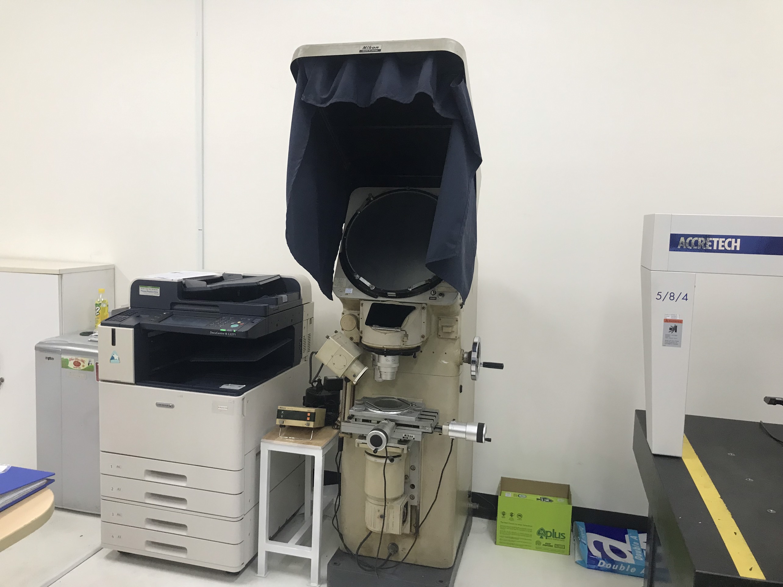

Using a CMM to inspect dimensional accuracy of stamping parts sounds simple until a thin bracket fails inspection at your dock. Last year, our Vietnam team caught a batch where clamping force alone shifted hole positions out of tolerance. The part was fine. The measurement was wrong. That gap between real accuracy and measured accuracy costs importers rework, returns, and lost trust. The fix is a disciplined CMM workflow built specifically for stamped sheet metal.
To inspect dimensional accuracy of stamping parts with a CMM, fixture the part without distorting it, align it to the drawing datums, calibrate and select the right probe, measure critical features like holes and flanges, then compare results against CAD nominals and GD&T tolerances in a deviation report.
That is the short answer. But stamped parts are thin, springy, and reflective, so each step hides traps. Let me walk you through the process the way we run it on real customer projects.
What CMM Inspection Steps Should I Follow for Stamping Parts?
During a supplier audit 1 in Vietnam, I once watched an inspector probe a stamped clip before it had acclimatized from a hot workshop. Every hole read undersize. Sequence matters more than most buyers realize.
Follow seven steps: acclimatize the part to a controlled temperature, calibrate the probe, fixture the stamping without distortion, align it to the datum reference frame, measure critical features, compare measured points to CAD or drawing nominals, and export a deviation report with pass/fail status.
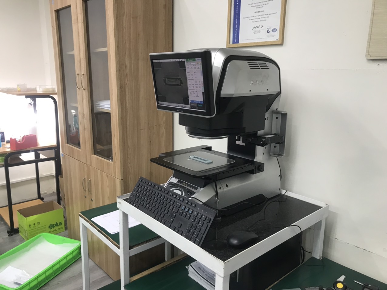
Each step exists to remove one source of error. Skip a step, and you no longer know whether a deviation comes from the part or from the setup. Here is how we structure the workflow when we run first-article or PPAP inspections 2 on stamped brackets and clips for our U.S. clients.
The Seven-Step Workflow in Detail
- Acclimatize the part. Sheet metal expands and contracts with heat. Let parts sit in the metrology room until they reach a stable temperature, ideally around 20 ± 1°C.
- Calibrate the probe. Qualify the stylus against a reference sphere before every session. A worn or dirty stylus tip corrupts every point that follows.
- Fixture the part. Support the stamping the way it sits in the final assembly. Use light clamping so thin sections do not bow.
- Align to datums. Build the coordinate system from the datum features called out on the drawing, in the correct order, before measuring anything else.
- Measure critical features. Probe hole centers, slot locations, flange planes, bend zones, and edge profiles per the control plan.
- Compare to nominals. Let the software calculate deviations against CAD or 2D drawing values and GD&T tolerances.
- Report and archive. Export the deviation report, save the raw point files, and record the timestamp for traceability.
Why Sequence Discipline Pays Off
We also run a dry-run simulation of the probe path before live measurement. This catches collisions and wasted moves. On repeat orders, we rerun a repeatability check 3 on one golden part to confirm the program is still stable. When a bracket for one of our American clients showed drift over three lots, that repeatability check told us the fixture had loosened — not the die. That saved a needless die correction and a week of delay.
Which Dimensional Tolerances Matter Most When Inspecting Stamping Parts with a CMM?
A purchasing manager once asked me why his supplier's report listed forty dimensions but missed the two hole positions that actually mated with his assembly. Not all tolerances carry equal weight.
The most critical tolerances for stamped parts are hole true position, flatness, profile of formed surfaces, bend angle, edge-to-edge dimensions, and datum-to-feature relationships. These control fit and function in assembly, so they should be prioritized on every CMM inspection plan under ASME Y14.5 GD&T.
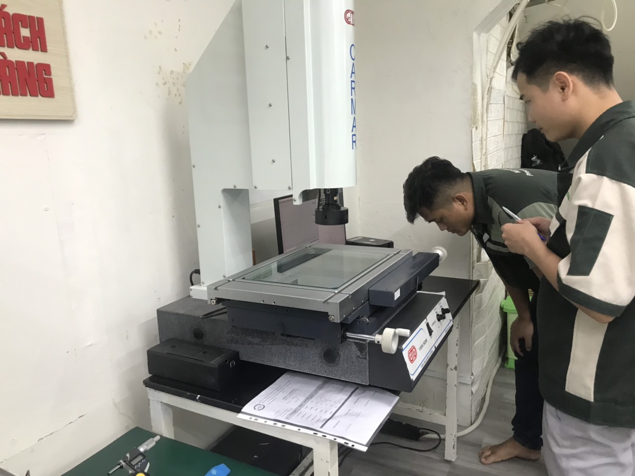
Stamped parts live or die on relationships, not raw sizes. A hole can be perfectly round yet sit in the wrong place. A flange can measure the right length yet bend two degrees off. On our projects, we build the inspection plan 4 around the features that touch mating parts first, then work outward. The table below shows how we rank tolerances on a typical stamped bracket with two mounting holes and folded flanges.
Tolerance Priority for Typical Stamped Parts
| Tolerance Type | What It Controls | Why It Matters for Stampings | Typical Risk if Missed |
|---|---|---|---|
| True position of holes | Hole location vs. datums | Fastener alignment in assembly | Parts will not bolt together |
| Flatness | Warp of mounting faces | Sealing, seating, stack-up | Rocking, gaps, vibration |
| Profile of a surface | Formed contours vs. CAD | Springback control on bends | Interference with mating parts |
| Bend angle | Flange orientation | Fit of Z-folds and channels | Clips lose spring tension |
| Edge-to-edge size | Trimmed blank dimensions | Clearance in enclosures | Parts jam or rattle |
| Slot width and location | Adjustment features | Sliding fit and tolerance absorption | Loss of adjustability |
Springback Changes Which Tolerances Are Fragile
Springback deserves special attention. When steel or aluminum sheet 5 is bent, it relaxes slightly after the punch retracts. So bend angle and profile tolerances drift far more than punched hole diameters. Hole size comes from the punch and stays stable. Hole position relative to a bend, however, moves whenever the bend moves. On the spring clips we source, we always probe the bend zone and the hole pattern together, in the same alignment, so the report shows the true functional relationship. We also confirm whether the drawing calls for free-state or restrained-state measurement 6. Thin parts can pass restrained and fail free — and that distinction must be settled with the customer before inspection, not argued afterward.
How Do I Choose Between Contact and Non-Contact CMM Methods for Stamping Parts?
The trade-off I weigh most often on stamped parts is probe force versus surface access. A stylus gives precision, but it also pushes on metal that may only be half a millimeter thick.
Use contact probing for hole positions, datums, and tight-tolerance features because it delivers the highest point accuracy. Use non-contact optical or blue-light scanning for thin flexible parts, reflective surfaces, and complex formed features like ribs and beads where stylus force or access is a problem.

Neither method wins everywhere. The right choice depends on part stiffness, surface finish, tolerance band, and how many points you need. Here is the comparison we use when planning inspection for a new stamped component.
Contact vs. Non-Contact at a Glance
| Factor | Contact (Touch-Trigger / Scanning Probe) | Non-Contact (Optical / Blue-Light) |
|---|---|---|
| Point accuracy | Highest, ideal for tight tolerances | Good, but slightly lower per point |
| Thin flexible parts | Risk of deflection from probe force | No force applied, no deflection |
| Reflective surfaces | Unaffected by shine | May need spray or exposure tuning |
| Data density | Low to medium, targeted points | Millions of points, full surface map |
| Formed ribs and beads | Stylus access can be blocked | Captures complex geometry easily |
| Speed on full-surface checks | Slow | Fast |
| Best use on stampings | Holes, slots, datums, key planes | Profile, springback, contour maps |
Our Hybrid Approach in Practice
On most stamped projects, we combine both. For a thin cover plate we sourced for a U.S. client, the flatness callout was the headache. A touch probe with standard force bowed the sheet at unsupported spots, and the readings jumped. We switched to a low-force scanning routine over supported zones and used optical scanning for the open field. The color deviation map showed real warp from the die, not fixture noise.
A few practical rules guide us. First, use the shortest, stiffest stylus that reaches the feature — long slender styli flex and add error. Second, when scanning shiny zinc-plated or brushed surfaces, verify the scanner settings on a sample before running the lot. Third, always tie both data sets to the same datum alignment 7 so contact and scan results can be compared in one report. Mixing coordinate systems creates confusion that no amount of data density can fix.
What CMM Inspection Reports Should I Request from My Stamping Parts Supplier?
Early in our export business, a client returned a lot because the supplier's report listed only "OK/NG" with no numbers. That taught us: a report without actual measured values is not evidence, it is an opinion.
Request a dimensional layout report showing each ballooned dimension, its nominal value, tolerance, actual measured value, deviation, and pass/fail status. For PPAP or critical parts, also request the datum alignment record, calibration status, environmental conditions, raw point data, and SPC trend data across lots.
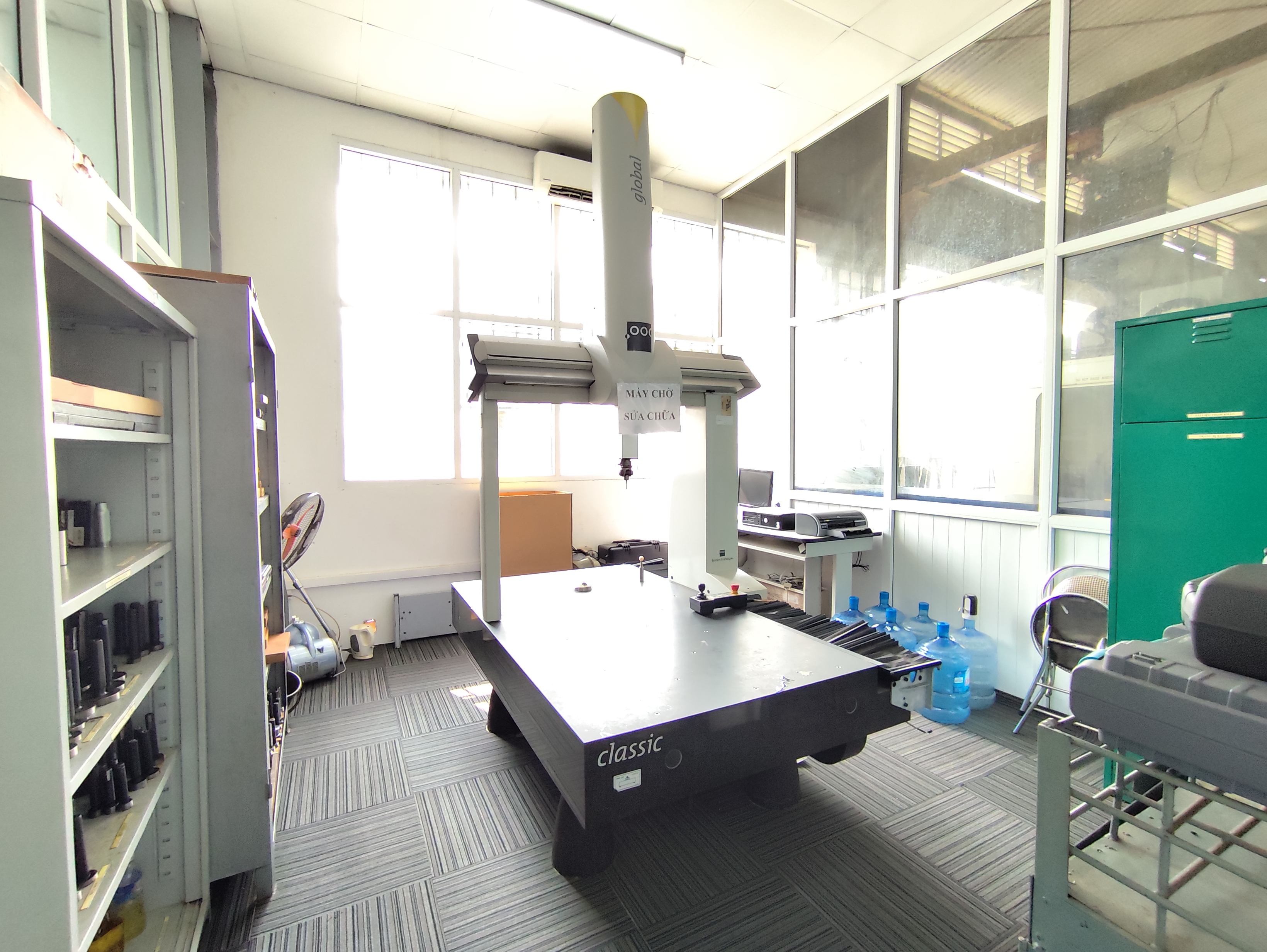
A strong report lets you verify the measurement, not just accept the verdict. When we prepare final inspection documentation for our clients in the United States and Europe, we structure it so their quality engineers can audit every number without flying to Asia. The checklist below covers what a complete package should contain.
Report Elements to Demand
| Report Element | What It Tells You | When to Require It |
|---|---|---|
| Ballooned drawing with numbered dimensions | Links each result to a drawing feature | Every report |
| Nominal, tolerance, actual, deviation columns | Actual values, not just pass/fail | Every report |
| Datum alignment method used | Whether the reference frame matches the print | Every report |
| Free-state vs. restrained-state note | How thin parts were held during measurement | Thin or flexible stampings |
| CMM calibration certificate reference | Machine traceability, e.g., ISO 10360 testing | PPAP, first article, audits |
| Temperature and humidity log | Environmental validity of the results | Tight-tolerance parts |
| Raw point files with timestamps | Auditability and re-analysis capability | PPAP and disputes |
| Color deviation map from scanning | Visual springback and warp behavior | Formed contours and profiles |
| SPC trend charts across lots | Lot-to-lot process stability | Ongoing production |
Reading the Report Critically
Do not stop at the pass/fail column. Look at where actual values sit inside the tolerance band. A dimension at 90% of tolerance on the first article will likely drift out during production. When we see that pattern, we push the deviation data back to the tooling side so the die can be corrected at the specific bend or trim station causing it. Also confirm the report references the correct drawing revision. A perfect inspection against an outdated print is worthless. Finally, ask how many parts were measured. One good part proves the die can make a good part. A sampled layout across the lot proves the process holds.
Conclusion
Bad measurements cost as much as bad parts. Control temperature, fixturing, datums, probe choice, and reporting, and your CMM results on stamping parts become evidence you can trust.
Frequently Asked Questions
What CMM Inspection Steps Should I Follow for Stamping Parts?
During a supplier audit 1 in Vietnam, I once watched an inspector probe a stamped clip before it had acclimatized from a hot workshop. Every hole read undersize. Sequence matters more than most buyers realize.
Which Dimensional Tolerances Matter Most When Inspecting Stamping Parts with a CMM?
A purchasing manager once asked me why his supplier's report listed forty dimensions but missed the two hole positions that actually mated with his assembly. Not all tolerances carry equal weight.
How Do I Choose Between Contact and Non-Contact CMM Methods for Stamping Parts?
The trade-off I weigh most often on stamped parts is probe force versus surface access. A stylus gives precision, but it also pushes on metal that may only be half a millimeter thick.
Footnotes
1. ISO provides global standards guiding supplier quality audits referenced in the text. ↩︎
2. PPAP is a formal automotive quality standard buyers should understand when reviewing supplier inspection reports. ↩︎
3. NIST is the authoritative U.S. body on measurement science and repeatability standards. ↩︎
4. ISO 9001 outlines quality management principles underlying structured inspection planning. ↩︎
5. Background on sheet metal material behavior relevant to springback discussion. ↩︎
6. GD&T concepts define free-state versus restrained-state measurement conditions for thin parts. ↩︎
7. ASME Y14.5 is the governing standard for datum alignment and GD&T practices. ↩︎