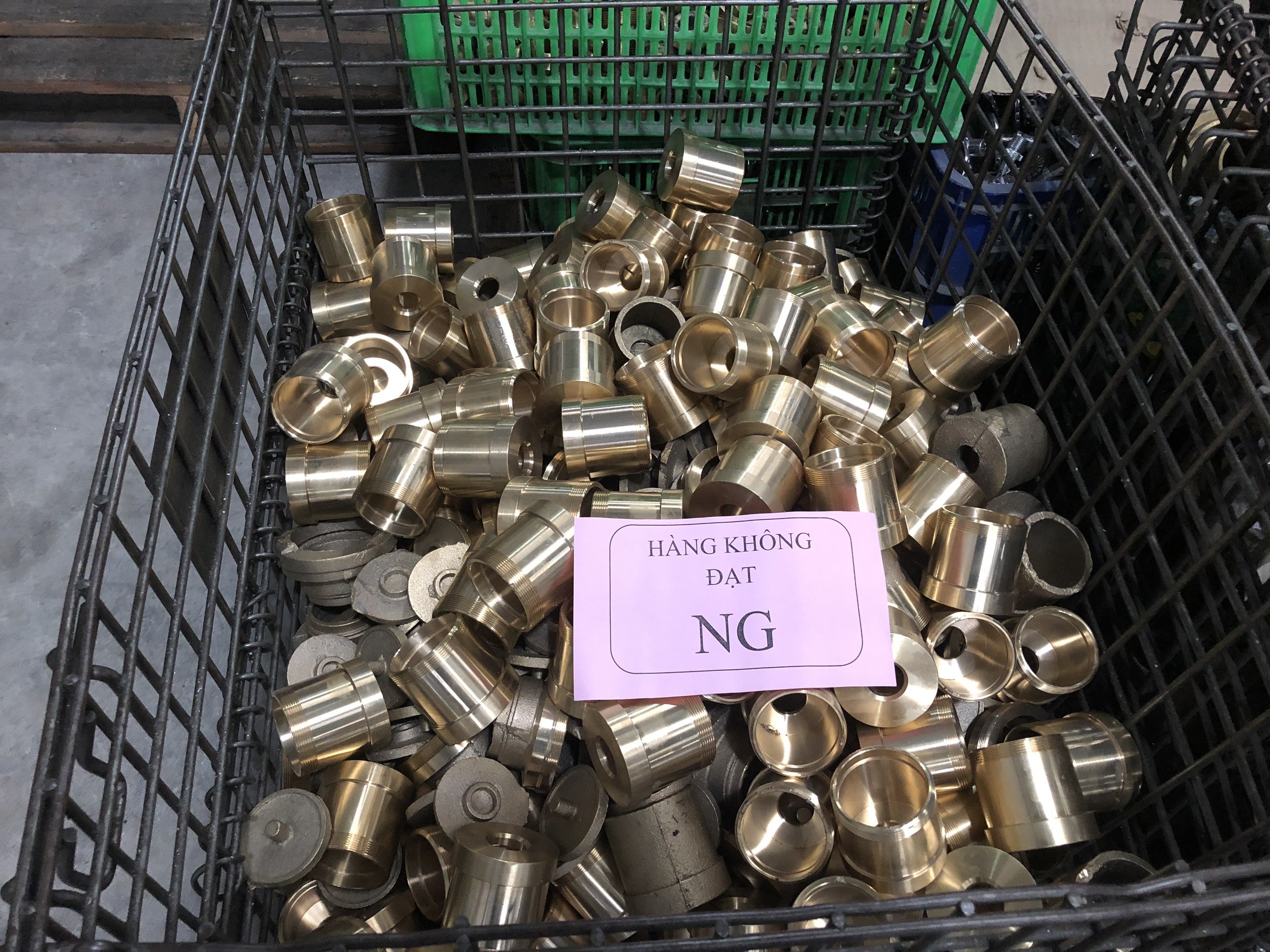

Sourcing sheet metal fabrication 1 from overseas suppliers can feel like a gamble — one wrong bend radius, one missed tolerance, and you receive parts that don’t fit. When our team in Vietnam and China manages custom part programs for U.S. clients, the most painful failures we see trace back to skipped verification steps during rapid prototyping 2 or reverse engineering.
To verify rapid prototyping and reverse engineering when sourcing sheet metal fabrication, request dimensional inspection reports, validate CAD models against original designs using 3D scanning services, confirm Design for Manufacturability compliance, and require first-article samples that match production-grade material specifications before approving full runs.
This guide breaks down the practical steps you need at each stage coordinate measuring machines 3. We will cover prototype quality assurance, reverse engineering 4 validation, tolerance verification, and the exact documentation to demand from your supplier.
How do I ensure my sheet metal prototype will accurately reflect the quality of the final production run?
A lesson we learned early in our supply chain work: a prototype that looks right but uses the wrong material or process will mislead every downstream decision. Our engineers now insist on matching production conditions from the very first sample.
Ensure your sheet metal prototype reflects final production quality by requiring the supplier to use identical materials, the same fabrication processes (laser cutting, bending, welding), and full dimensional inspection at each stage — design review, CAD modeling, production, and quality control process verification.

The Four-Step Prototyping Workflow
Every reliable sheet metal prototype follows four steps. Missing any one of them invites defects into your production run.
| Step | What Happens | What You Verify |
|---|---|---|
| 1. Design Review | Supplier reviews your drawings for feasibility | DFM feedback, bend radii, hole spacing |
| 2. Digital Modeling (CAD) | 3D CAD model is created or refined | Dimensional accuracy, flat pattern layout |
| 3. Production | Laser cutting, bending, punching, welding | Process matches final production method |
| 4. Quality Inspection | Parts measured against specifications | Tolerances, surface finish, assembly fit |
When we manage prototyping programs, we require our suppliers to submit a brief report after each step. This prevents surprises. If a bend radius needs to change for manufacturability, we want to know at Step 1 — not after parts are cut.
Why Material Selection Matters More Than You Think
Some suppliers will propose a cheaper or easier-to-form material for prototypes. That saves time, but it destroys your design validation. If your final part is 304 stainless steel 5, your prototype must be 304 stainless steel. The springback behavior, weld characteristics, and surface finish of mild steel or aluminum are completely different. A prototype in the wrong material tells you nothing about how the real part will perform.
We once had a client whose supplier prototyped a mounting bracket in mild steel instead of the specified 1.5 mm 304 stainless. The prototype fit perfectly. But in production, the stainless steel's higher springback opened the bend angles by two degrees, and every bracket failed assembly. That rework cost three weeks and thousands of dollars. Match the material. Match the process. No shortcuts.
Applying DFM Principles Early
Design for Manufacturability 6 is not just a buzzword. It is a concrete checklist that prevents prototype revisions and ensures production scalability. Here are the DFM principles we apply to every sheet metal project:
- Use consistent bend radii (ideally equal to or greater than material thickness)
- Keep holes and cutouts at least one material thickness away from bend lines
- Avoid tolerances tighter than ±0.1 mm unless functionally necessary
- Align features with standard tooling to avoid custom die costs
- Minimize the number of unique setups required
When DFM is applied at the prototype stage, the transition to full production is smooth. When it is skipped, you get a beautiful prototype that cannot be made at volume — or that requires expensive custom tooling.
What is the best way for me to verify the accuracy of a reverse-engineered part against my original design?
A client recently shipped us a worn-out mounting bracket — no drawings, no CAD files, just the physical part. They needed us to recreate it for a new production run. This is where reverse engineering meets real-world sourcing, and where errors multiply if you skip verification.
Verify reverse-engineered accuracy by comparing the reconstructed CAD model against the original part using 3D scanning services and coordinate measuring machines (CMMs). Overlay the scan data on the CAD model reconstruction, check all critical dimensions, and perform a fit test with mating components before approving production.

The Reverse Engineering Process for Sheet Metal
Reverse engineering a sheet metal part is not simply measuring it with calipers. Worn edges, deformed surfaces, and missing features mean you need a systematic approach. Here is how we handle legacy part recreation:
- 3D Scanning — We use laser or structured-light scanners to capture the part's full geometry as a point cloud.
- CAD Model Reconstruction — Our engineers convert the scan data into a parametric CAD model, adding design intent (true radii, symmetry, standard hole sizes).
- Comparison and Deviation Analysis — The CAD model is overlaid on the scan data. A color map shows deviations. We flag any area that exceeds the agreed tolerance.
- DFM Review — The reconstructed model is checked for manufacturability. Some features on old parts were made with processes no longer practical.
- Prototype and Fit Test — A first-article sample is made and tested against mating components.
What to Look for in a Deviation Report
When your supplier sends you a comparison report, focus on these metrics:
| Metric | Acceptable Range | Red Flag |
|---|---|---|
| Surface deviation (scan vs. CAD) | ±0.15 mm for general features | > ±0.3 mm on critical mating surfaces |
| Hole position accuracy | ±0.1 mm | > ±0.2 mm on mounting holes |
| Bend angle deviation | ±0.5° | > ±1.0° on structural bends |
| Overall profile tolerance | ±0.2 mm | > ±0.5 mm on assembled contours |
| Edge straightness | ±0.1 mm per 100 mm | Visible waviness or burrs |
If your supplier cannot produce this type of deviation report, that is a warning sign. Modern 3D scanning services 7 and CAD tools make this straightforward. Any shop doing serious reverse engineering should have these capabilities or partner with a metrology lab.
Fit Testing Is Non-Negotiable
Numbers on a report are helpful, but the ultimate test is physical assembly. We always request that the supplier assemble the reverse-engineered part with its mating components. If the bracket mounts to a housing, bolt it on. If the enclosure mates with a PCB, check clearances. This step catches issues that dimensional reports miss — things like interference from weld beads, slight warping from heat input, or fastener alignment under load.
For one project involving a pair of mirrored industrial mounting brackets with complex angular folds and multiple pre-drilled holes, the scan-to-CAD comparison looked perfect. But during assembly, we discovered that the weld marks at the joints created a 0.3 mm protrusion that prevented flush mounting. The supplier adjusted the weld sequence, and the second sample fit correctly. Without that physical test, the issue would have reached production.
How can I evaluate if a supplier's rapid prototyping process will meet my strict tolerance requirements?
Before we onboard any new fabrication supplier in Vietnam or China, we run a capability assessment. We send a test part — not the actual production part — and measure what comes back. The results tell us more than any factory tour or sales presentation ever could.
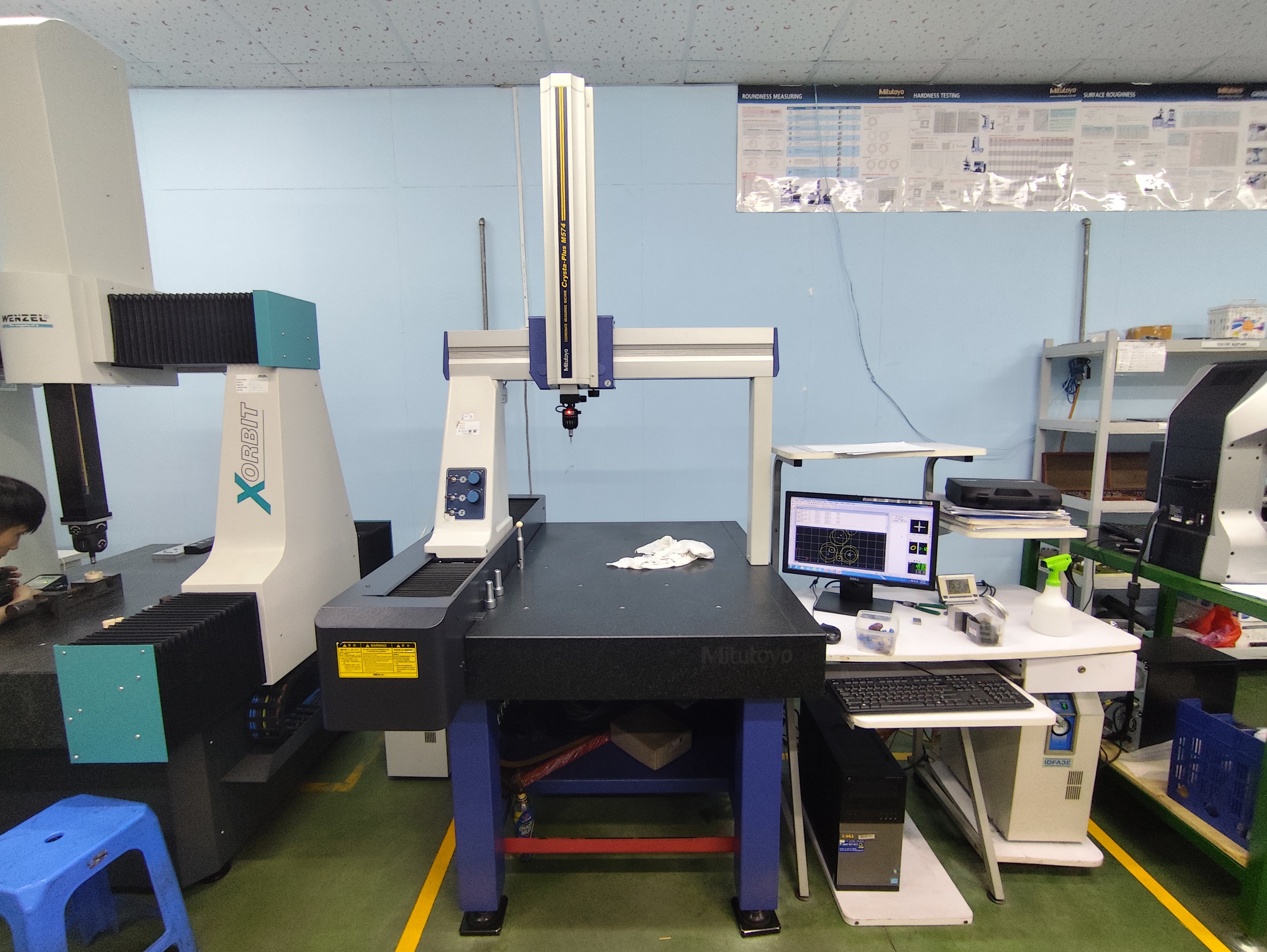
Evaluate a supplier's tolerance capability by requesting a first-article inspection report with CMM data, reviewing their equipment list (laser cutter accuracy, press brake repeatability), and comparing measured dimensions against your drawing tolerances. Ask for a Cpk analysis on critical dimensions if volumes justify it.
Equipment and Process Capability
Not all rapid prototyping setups are equal. The machines a supplier uses directly determine the dimensional accuracy they can achieve. Here is a comparison of common sheet metal fabrication methods and their typical tolerances:
| Process | Typical Tolerance | Best For | Limitation |
|---|---|---|---|
| Fiber Laser Cutting | ±0.05 mm | Complex profiles, thin to medium gauge | Edge quality depends on power settings |
| CNC Turret Punching | ±0.1 mm | High-volume hole patterns | Limited to standard tool shapes |
| CNC Press Brake Bending | ±0.1° – ±0.5° | Precise bends on long parts | Springback varies by material |
| Robotic Welding | ±0.3 mm | Consistent weld placement | Fixturing cost for small batches |
| Manual TIG Welding | ±0.5 mm | Prototypes, complex joints | Operator-dependent quality |
When I review a supplier's equipment list, I look for CNC-controlled machines with regular calibration records. A shop using a manual brake with no angle measurement system will not hold ±0.5° on a multi-bend bracket. Period.
How to Structure a Tolerance Verification Test
Here is the process we follow:
- Select a test geometry — Pick a part with features similar to your production part: multiple bends, hole patterns, and at least one tight tolerance callout.
- Send the drawing with GD&T — Include clear tolerance callouts. If the supplier asks for clarification, that is actually a good sign.
- Request a first-article inspection report (FAIR) — This should include measured values for every dimensioned feature, ideally from a CMM.
- Compare results — Check how close the measured values are to nominal. Look at the spread. If three samples all show the same 0.08 mm deviation on a hole position, the machine has a consistent offset that can be corrected. If the spread is random, the process is not capable.
- Ask about lead time reduction strategies — A supplier confident in their process will offer fast turnaround for prototypes because they know their machines and do not need excessive trial-and-error.
Sheet Metal Prototyping vs. Other Methods
Some buyers wonder whether 3D printing or CNC machining might be better for verifying tolerances. For functional metal parts, sheet metal prototyping is almost always the right choice. 3D-printed metal parts have different grain structures, surface finishes, and mechanical properties. CNC-machined parts are solid, not formed — so they cannot replicate bend behavior. Only a sheet metal prototype made with the same processes as production will give you a true tolerance verification.
That said, 3D printing can be useful for checking fit and clearance on non-critical plastic components in an assembly. Use the right tool for the right job.
What documentation should I request to confirm my supplier has successfully reverse-engineered my custom sheet metal part?
During a recent project, we asked a supplier for "proof" that their reverse-engineered part matched the original. They sent us a photo. Just a photo. That is not documentation — that is marketing. Real verification requires structured records that you can audit and archive.
Request a complete documentation package including the original 3D scan data, reconstructed CAD model with flat pattern, a scan-to-CAD deviation report, a first-article inspection report with CMM measurements, material certificates, and a process sheet detailing all fabrication steps used to produce the reverse-engineered part.
The Complete Documentation Checklist
Here is the documentation package we require from every supplier on reverse engineering projects. We share this checklist with the supplier before work begins so expectations are clear.
| Document | Purpose | Format |
|---|---|---|
| 3D Scan Data | Raw point cloud or mesh of the original part | STL, OBJ, or proprietary scan format |
| Reconstructed CAD Model | Parametric model for manufacturing | STEP, IGES, or native CAD format |
| Flat Pattern Drawing | Verifies bend allowances and blank size | DXF or PDF |
| Scan-to-CAD Deviation Report | Shows dimensional accuracy of reconstruction | PDF with color map |
| First-Article Inspection Report 8 (FAIR) | Measured vs. nominal dimensions on the prototype | PDF or Excel with CMM data |
| Material Certificate (Mill Cert) | Confirms material grade, thickness, and properties | PDF from material supplier |
| Process Sheet | Lists all fabrication steps: cutting, bending, welding, finishing | PDF or supplier's internal form |
| Assembly Fit Test Report | Documents fit with mating components | Photos, measurements, pass/fail notes |
Why Each Document Matters
The 3D scan data is your baseline. If questions arise later about dimensional accuracy, you can re-analyze the scan. The reconstructed CAD model is what the supplier uses to create tooling paths and flat patterns. Without it, you cannot reproduce the part if you switch suppliers.
The deviation report is where you see the quality of the reconstruction. A good supplier highlights areas where they made design-intent decisions — for example, rounding a worn edge to a true radius or correcting an out-of-square bend on the original. These decisions should be documented, not hidden.
The first-article inspection report ties everything together. It proves the physical part matches the CAD model, which matches the original scanned part. If any link in that chain is broken, your production run is at risk.
Material certificates protect you from substitution. We have seen cases where a supplier specified 316 stainless on the drawing but used 304 in production. The mill certificate is the only way to verify the material specifications objectively.
Protecting Your Intellectual Property
When sourcing custom parts through reverse engineering, IP protection is a real concern. Our approach includes several practical steps:
- Use non-disclosure agreements 9 (NDAs) before sharing any part or drawing
- Describe parts generically in communications (e.g., "custom stainless sheet bracket" instead of the product name or application)
- Split complex assemblies across multiple suppliers so no single vendor sees the complete design
- Maintain ownership of all CAD files and scan data — the supplier produces them, but you own them
These steps do not guarantee absolute protection, but they raise the bar significantly. For our U.S. clients sourcing from Asia, this layered approach to IP management is standard practice on every project we manage.
Conclusion
Verifying rapid prototyping and reverse engineering when sourcing sheet metal fabrication requires structured steps: match production materials, apply DFM early, demand 3D scan verification, and insist on complete documentation before approving any production run.
Frequently Asked Questions
How do I ensure my sheet metal prototype will accurately reflect the quality of the final production run?
A lesson we learned early in our supply chain work: a prototype that looks right but uses the wrong material or process will mislead every downstream decision. Our engineers now insist on matching production conditions from the very first sample.
What is the best way for me to verify the accuracy of a reverse-engineered part against my original design?
A client recently shipped us a worn-out mounting bracket — no drawings, no CAD files, just the physical part. They needed us to recreate it for a new production run. This is where reverse engineering meets real-world sourcing, and where errors multiply if you skip verification.
How can I evaluate if a supplier's rapid prototyping process will meet my strict tolerance requirements?
Before we onboard any new fabrication supplier in Vietnam or China, we run a capability assessment. We send a test part — not the actual production part — and measure what comes back. The results tell us more than any factory tour or sales presentation ever could.
Footnotes
1. Provides a comprehensive guide to sheet metal fabrication processes and applications. ↩︎
2. Explains the concept and applications of rapid prototyping. ↩︎
3. Replaced unknown HTTP status with a comprehensive Wikipedia article on coordinate measuring machines, an authoritative overview. ↩︎
4. Defines the process of reverse engineering and its common uses. ↩︎
5. Replaced HTTP 404 with an authoritative article from IQS Directory detailing 304 stainless steel properties and uses. ↩︎
6. Explains DFM as an engineering method to optimize product design for easier, cheaper manufacturing. ↩︎
7. Describes the technology and applications of 3D scanning for digital models. ↩︎
8. Replaced HTTP 404 with an authoritative explanation of first-article inspection reports from OpenBOM. ↩︎
9. Explains NDAs as legal contracts to protect confidential information. ↩︎