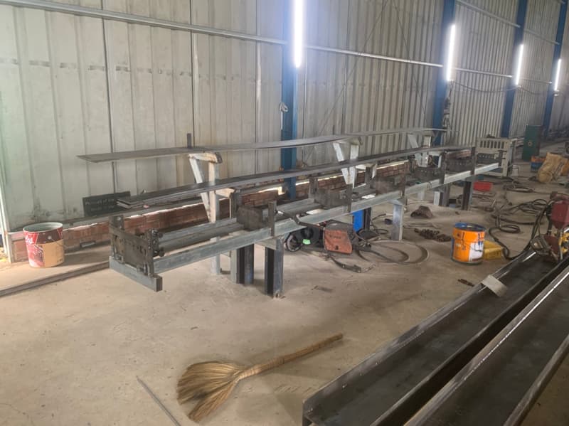
Weld distortion in complex sheet metal assemblies is driven primarily by localized, non-uniform thermal expansion and contraction during heating and cooling cycles. When joining thin-gauge sheet metal (typically 0.8 mm to 6.0 mm), thermal gradients create residual internal stresses that exceed the yield strength of the base alloy, causing buckling, angular warping, longitudinal shrinkage, and transverse distortion.
To control distortion effectively, Design for Manufacturability (DFM) must intervene at the CAD and joint-architecture stage—long before parts reach the welding bay. Key strategies include minimizing deposited weld volume, balancing weld locations around structural neutral axes, integrating tab-and-slot self-fixturing details, utilizing intermittent (stitch) welding where structural integrity permits, and enforcing strict tolerance standards such as ISO 13920.
1. Thermal Mechanics & Material Behavior in Weld Distortion
Understanding weld distortion requires analyzing four distinct deformation modes:
- Angular Distortion: Caused by non-uniform transverse shrinkage across the depth of a fillet or groove weld, pulling parts toward the wider side of the weld crown.
- Longitudinal Shrinkage: Contraction along the axis of the weld seam, leading to bowing along thin-walled fabrications.
- Transverse Shrinkage: Contraction perpendicular to the weld seam, pulling joined edges inward.
- Buckling & Oil-Canning: Instability caused by compressive residual stresses acting on high-aspect-ratio, thin-gauge sheet panels.
Material Selection Trade-Offs
Material thermal properties dictate susceptibility to warping. Austenitic stainless steels (e.g., AISI 304/316) exhibit a thermal expansion coefficient ~50% higher than carbon steels, combined with lower thermal conductivity, making them particularly prone to severe thermal distortion.
| Material Grade | Thermal Conductivity (W/m·K) | Coeff. of Thermal Expansion (µm/m·°C) | Distortion Susceptibility | Recommended DFM Focus |
|---|---|---|---|---|
| Carbon Steel (ASTM A1008 / A36) | ~50 | ~12.0 | Moderate | Standard clamp fixturing & staggered sequencing |
| Austenitic Stainless (AISI 304/316) | ~16 | ~16.0–18.0 | High | Minimal weld volume, stitch welding, heat sinks/chill bars |
| Aluminum Alloy (5052-H32 / 6061-T6) | ~130–167 | ~23.0 | High (due to expansion) | Low heat input (Pulsed TIG/Laser), rigid fixturing |
For precision structures, engineers rely on international standard ISO 13920 (Tolerances for welded structures), which defines functional tolerance classes for linear dimensions (Classes A through D) and angular dimensions (Classes A through D). Specifying Class A or B requires rigorous heat input control during production.
Suppliers such as Hdp Precision Mechanical Engineering—which lists Sheet Metal capabilities alongside equipment such as a Bending Machine, CNC Milling Machine, and a 2D Measuring Machine—utilize mechanical processing to ensure post-weld components align with tight dimensional standards. For full equipment specifications and plant profiles, review our Precision Sheet Metal & Laser Bending capability directory.
2. Joint Design & DFM Engineering Rules
Controlling distortion requires reducing net heat input and balancing structural reaction forces.
flowchart TD
    A[CAD Design Phase] --> B{Is Structural Weld Continuous?}
    B -- No --> C[Specify Intermittent / Stitch Welding]
    B -- Yes --> D{Panel Thickness < 3.0 mm?}
    D -- Yes --> E[Use Tab-and-Slot Alignment & Laser / Micro-TIG]
    D -- No --> F[Design Symmetrical Double-V or Intermittent Opposing Fillets]
    C --> G[Apply Presetting / Pre-Bending along Neutral Axis]
    E --> G
    F --> G
    G --> H[Final Assembly Fixturing & Sequenced Tacking]
Practical DFM Rules for Weld Joint Design
- Minimize Weld Deposit Size: Fillet weld strength scales linearly with throat size, while volume (and heat) scales quadratically. Oversizing a fillet weld from 3 mm to 6 mm quadruples deposited metal and heat input without proportional benefit.
- Symmetrical Joint Placement: Place welds symmetrically about the neutral axis of the assembly to cancel opposing shrinkage vectors.
- Tab-and-Slot Self-Fixturing: Incorporate laser-cut tabs and mating slots into folded panels. This fixes spatial orientation prior to welding, eliminating reliance on heavy external clamping that can induce high residual stress.
- Intermittent (Stitch) Welding: Where continuous liquid/gas seal is not required, specify staggered intermittent welds (e.g., 25 mm weld per 100 mm pitch) to drastically cut thermal exposure.
- Use Cold-Formed Bends Over Welded Corners: Replace two-piece welded corner joints with press-brake bends wherever component envelope geometry permits.
3. Precision Manufacturing Capabilities in Vietnam
Evaluating manufacturing partner capabilities is essential when sourcing distortion-critical assemblies. Within the DEWIN supplier database, there are 179 listed Vietnamese suppliers across 37 industrial categories, including 17 suppliers categorized under Sheet Metal and 5 under Metal Fabrication. On-file shop-floor equipment across listed factories includes 29 listing bending machines, 7 listing CNC laser cutting machines, and 7 listing general laser cutting machines.
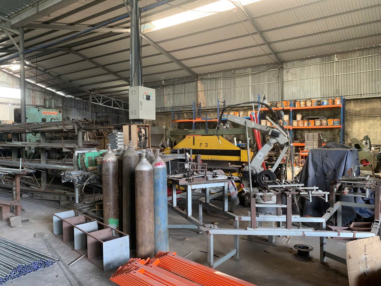
Precision fabricators maintain thermal stability across complex fabrications by combining laser cutting, pre-forming, mechanical fixturing, and sequenced welding processes. Fabricators such as Viet Thanh Mechanical Production Co. Ltd—whose listed equipment includes a Bending machine, CNC cutting machine, and CNC lathe machines—combine cutting and bending capabilities to minimize unnecessary welded seams.
Specific supplier credentials, quality certifications (e.g., ISO 9001, ISO 3834), production lead times, and unit capacities are not on file in the aggregate database and must be verified directly on a per-project basis during the RFQ process.
4. Engineering RFQ Guidelines for Distorted-Free Assemblies
When preparing technical documentation and requests for quotation (RFQs) for complex sheet metal assemblies, procurement engineers should include explicit controls:
- Define Tolerance Framework: Standardize drawings according to ISO 13920-B (or AWS D1.1/D1.2) rather than applying unachievable general machining tolerances across sheet fabrications.
- Specify Weld Sequences: Indicate critical sequence requirements on assembly drawings (e.g., back-step welding, center-outward sequence, or symmetrical opposing tacks).
- Mandate Inspection Fixtures: Require dedicated check fixtures (CMM or flush-and-gap tooling) for sub-assemblies before final welding.
- Clarify Post-Weld Processing: Define whether mechanical flattening, flame straightening, or stress-relief heat treatment is permitted or required prior to coating.
To explore technical fabrication capabilities, review our Sheet Metal Fabrication Services, inspect verified supplier shop floors in the DEWIN Supplier Directory, or submit your CAD models for a technical DFM review through our Instant Quote Engine or Engineering RFQ Portal.
Frequently Asked Questions
What are the most effective DFM strategies to minimize weld distortion in thin sheet metal?
The most effective strategies include specifying intermittent stitch welding instead of continuous fillets where sealing is not required, incorporating laser-cut tab-and-slot self-fixturing features to align panels without high-stress clamping, placing weld seams symmetrically along structural neutral axes, and replacing welded corners with press-brake bends.
How does material selection impact thermal warping during welding?
Austenitic stainless steels (AISI 304/316) exhibit a coefficient of thermal expansion roughly 50% higher than carbon steel and lower thermal conductivity, making them far more susceptible to severe angular distortion and oil-canning. Aluminum alloys also expand significantly and require pulsed TIG, laser welding, or copper chill-bar fixturing to dissipate heat rapidly.
What international standards govern welding tolerances for fabricated sheet metal structures?
ISO 13920 is the primary international standard defining tolerance classes for linear and angular dimensions of welded fabrications (Classes A through D). In structural steel engineering, AWS D1.1 and AWS D1.2 establish code criteria for joint preparation, fit-up tolerances, and procedure qualifications.