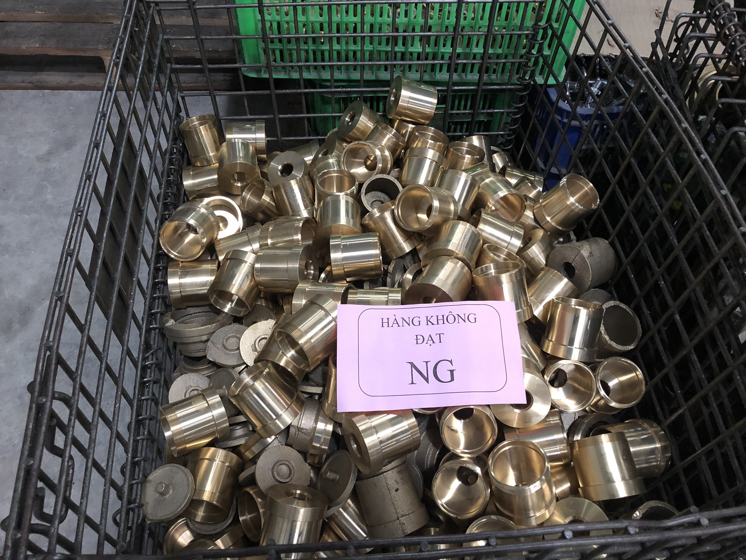
What Engineering Steps Control Quality in Driveline Forging and Broaching?
Driveline forging quality relies on a 16-stage vertically integrated process spanning bar cutting, cold or warm closed-die forging, isothermal normalizing, and 136 robotic CNC turning stations. Hydraulic pull broaching holds DIN 5480 spline specifications to ±0.008 mm concentricity, supported by CQI-9 carbonitriding furnace controls, eddy-current crack sorting, and ZEISS 3D CMM metrology.
Key Takeaways
- Engineering teams in Xi'an (26 staff) and Ho Chi Minh City (7 staff) oversee DFM tolerance analysis, QCLDM audits, and ZEISS CMM inspection across regional factory networks.
- Precision cold and warm driveline forging achieves ±0.008 mm spline concentricity and HRC 58–62 hardness through 16-stage integrated production and CQI-9 heat treatment.
- Powder metallurgy and metal injection molding utilize 15T to 680T presses, mesh-belt and vacuum sintering, and catalytic debinding for complex structural alloys and stainless steels.
Automotive driveline components such as CV joint star sleeves, trunnion brackets, and spline shafts require strict structural integrity. Manufacturing begins with raw steel bar cutting, isothermal annealing, shot blasting, and saponification before high-tonnage cold or warm closed-die forging. Isothermal normalizing ensures a uniform Ferrite-Pearlite grain structure across the forged blank.
Final geometry is established using high-speed hydraulic pull broaching and hard-turning cells, including 136 robotic CNC lathes and 4 German EMAG turning centers. Internal spline raceways maintain DIN 5480 or JIS B 1603 specifications with concentricity held within ±0.008 mm.
Heat treatment utilizes CQI-9 controlled carbonitriding furnaces to achieve a case depth of 0.85 to 1.25 mm and surface hardness of HRC 58–62. Quality assurance steps integrate automated 100% eddy-current crack sorting, magnetic particle inspection, ultrasonic cleaning, and 3D CMM metrology prior to vacuum anti-rust packaging.
- Closed-die forging equipment: 160T to 630T press capacity for uniform grain flow
- Spline broaching standards: DIN 5480 and JIS B 1603 internal spline modules
- Hardness control: CQI-9 continuous carbonitriding delivering HRC 58–62 case hardness
- Dimensional inspection: ZEISS and Mitutoyo 3D CMM contour and roughness lab verification
How Do Powder Metallurgy and MIM Systems Maintain Structural Component Tolerances?
Powder metallurgy and metal injection molding maintain tight tolerances through 15T to 500T automatic powder presses, 680T hydraulic presses, and catalytic debinding lines. Mesh-belt and vacuum sintering process iron, bronze, 304/316L, and 17-4PH stainless steel alloys, complemented by steam treatments and universal gear testing to meet 50 PPM defect benchmarks.
Powder metallurgy (PM) and Metal Injection Molding (MIM) provide high-volume efficiency for intricate structural gears, shock absorber pistons, and oil pump rotors. Compacting is managed on 15T to 500T CNC automatic powder presses, feeding mesh-belt sintering lines and steam-treatment furnaces to produce high-density iron-copper alloys and SAE 841 / Sint B50 oil-impregnated bronze bushings.
For high-density transmission components and vacuum-sintered parts, dedicated vacuum furnaces sinter 304 and 316L stainless steel structural elements. These parts undergo dimensional verification on gear profile testers and ZEISS 3D CMM equipment.
Complex 17-4PH and 316L stainless steel geometries utilize MIM technology supported by catalytic debinding, 680T hydraulic presses, and in-house EDM mold fabrication. Quality management protocols enforce 50 PPM defect benchmarks alongside PPAP Level 3 documentation.
- Compacting equipment: 15T to 500T CNC powder presses and 680T hydraulic presses
- Sintering technologies: Mesh-belt sintering, vacuum sintering, and steam treatment
- Material alloys: 17-4PH, 304/316L stainless steel, SAE 841 bronze, and iron-copper alloys
- Quality metrology: Universal gear profile testing, metallographic density checks, and 3D CMM reports
Which Bearing and Precision Machining Technologies Support Industrial Equipment?
Industrial equipment applications rely on single and multi-row slewing bearings from Ø200 mm to Ø5,000 mm, SF-1/SF-2 PTFE composite bushings, and bimetal bearings. Aerospace-grade 5-axis CNC machining centers, turn-mill compounds, and cleanroom fluoropolymer processing further deliver high-purity PTFE, PEEK, titanium, and Inconel components under AS9100D metrology standards.
Heavy industrial applications require heavy-duty bearing assemblies and high-precision CNC components. Slewing ring manufacturing encompasses single and double-row four-point contact ball, three-row roller, and crossed-roller bearings spanning outer diameters from Ø200 mm up to Ø5,000 mm. These assemblies are turned on 5m CNC vertical turning centers and hardened via medium-frequency induction lines.
Plain bearing production uses continuous bronze-powder sintering strip lines and automated roll-forming to produce SF-1/SF-2 PTFE composite bushings, JF-800 bimetal bearings, and JDB graphite-plugged bronze components. Spherical plain bearings (GE/GEG/GEZ series) and hydraulic rod ends feature bonded PTFE fabric liners and MoS2 phosphating surface treatments.
Aerospace and semiconductor hardware leverage 70+ sets of 5-axis and 4-axis CNC machining centers, turn-mill compounds, and slow-wire EDM. Precision parts are crafted from titanium, Inconel, aluminum, PEEK, PFA, and PTFE inside cleanroom assembly environments.
- Slewing ring scale: Ø200 mm to Ø5,000 mm contact ball and roller bearing assemblies
- Self-lubricating materials: SF-1/SF-2 PTFE composite, JF-800 bimetal, and graphite-plugged bronze
- Precision machining: 5-axis and 4-axis CNC turning, milling, and slow-wire EDM centers
- High-performance polymers: Cleanroom processed PTFE, PFA, FEP, PVDF, PEEK, and FFKM seals

How Are Progressive Stamping and Supply Chain Relocations Coordinated?
Supply chain relocations coordinate die transfers, robotic welding cells, and tooling fixtures across a 10-month timeline managed by local engineering teams. Production utilizes progressive stamping presses up to 315T, laser cutters, and 9 OTC/Panasonic welding robots to fabricate stamped structural frames and commercial brackets.
On-the-ground engineering hubs in Xi'an (26 staff) and Ho Chi Minh City (7 staff) coordinate supplier auditing, DFM reviews, progressive die tooling simulations, and pre-quote tolerance analyses. Engineering teams oversee production schedules and quality control standards across multi-country manufacturing hubs.
When transitioning production across regional facilities, engineers execute a structured 10-month relocation playbook. This process transfers progressive dies, welding fixtures, and QC gauges while maintaining quality standards and preventing supply chain interruptions.
Fabrication facilities run 33 stamping presses up to 315T, laser cutters, 22 robotic CNC milling machines, and 9 OTC/Panasonic MIG/TIG welding robots. Finished assemblies undergo 240hr+ ASTM B117 salt spray exposure, 1,500hr UV powder coat testing, and 5G vibration testing.
- Stamping force: Up to 315T press capacity paired with laser cutting and CNC bending
- Robotic welding: 9 OTC and Panasonic MIG/TIG welding cells for structural assemblies
- Relocation timeline: 10-month migration protocol for dies, fixtures, and QC gauges
- Surface treatment testing: 240hr+ ASTM B117 salt spray and 1,500hr UV resistance testing
Precision Manufacturing & Sourcing Specification Matrix
| Technical Dimension | Standard Commercial Grade | High-Precision OEM Export Grade | DEWIN Verification Protocol |
|---|---|---|---|
| Machining & Forming Tolerance | ISO 2768-m (±0.10 mm nominal) | ISO 2768-f (±0.01 mm – ±0.025 mm critical bores) | Calibrated 3D CMM & Air/Pin Gauging |
| Surface Roughness & Finish | Ra 1.6 – 3.2 µm as-machined / standard coat | Ra 0.4 – 0.8 µm precision ground / MIL-A-8625 anodized | Profilometer & Coating Thickness Gauge |
| Material & Alloy Certification | Supplier Mill Test Report (MTR) | Independent OES chemical & mechanical verification | EN 10204 3.1 + RoHS/REACH Compliance |
| Batch Inspection & Packaging | ISO 2859-1 (AQL 1.0 Major / 2.5 Minor) | Zero-defect critical features + VCI export crating | Pre-Shipment Inspection (PSI) Report |
Frequently Asked Questions
What quality inspection protocols verify dimensional accuracy for machined parts?
Dimensional inspection relies on ZEISS and Mitutoyo 3D Coordinate Measuring Machines (CMM), surface roughness meters, contour testers, and eddy-current crack detection. Engineering teams generate Level 3 PPAP documentation and material Certificates of Analysis (COA) to confirm part compliance.
What structural materials are available for custom powder metallurgy components?
Powder metallurgy processes utilize iron, copper, SAE 841 / Sint B50 oil-impregnated bronze, soft magnetic cores (SMC), and 304/316L or 17-4PH stainless steels processed through mesh-belt, steam-treatment, or catalytic debinding vacuum sintering.
How are large-diameter slewing bearings engineered and hardened?
Slewing bearings ranging from Ø200 mm to Ø5,000 mm feature four-point contact ball, three-row roller, or crossed-roller designs. Raceways undergo medium-frequency induction hardening, machined on 5m CNC vertical turning centers and gear hobbing equipment.
What testing procedures assess stamped metal assembly durability?
Stamped metal assemblies undergo cyclic load testing, 5G vibration testing, 240hr+ ASTM B117 salt spray testing, and 1,500hr UV powder coating exposure tests to evaluate mechanical fatigue and environmental resistance.