How Do Engineering Teams Oversee Multi-Stage Driveline Forging and Hard Turning?
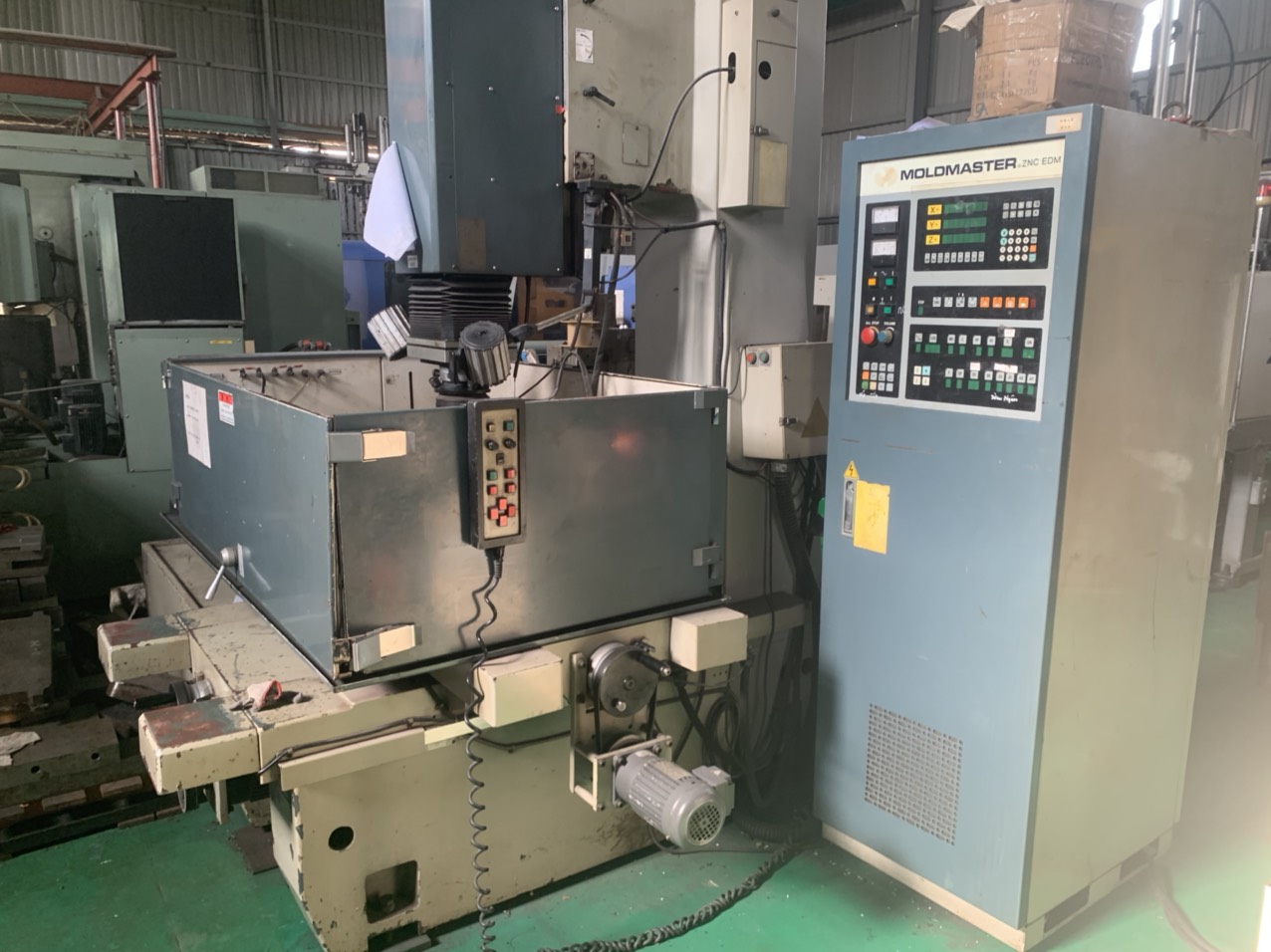
Engineering centers coordinate a 16-stage manufacturing flow for driveline components, starting with raw steel bar cutting and precision cold or warm forging. Automated 136-lathe CNC cells and EMAG turning lines maintain exact raceway concentricity before internal spline broaching, CQI-9 heat treatment, eddy-current crack detection, and ultrasonic cleaning.
Key Takeaways
- Xi'an and Ho Chi Minh City engineering centers manage factory audits, DFM reviews, and ZEISS CMM inspections across Asian manufacturing hubs.
- Driveline component production follows a 16-stage workflow, incorporating cold/warm precision forging, spline broaching, and CQI-9 heat treatment.
- Specialized Chinese facilities supply powder metallurgy, AS9100D-aligned 5-axis CNC machining, slewing bearings up to 5,000 mm, and technical fluoropolymers.
High-volume automotive driveline production, such as CV joint star-shaped sleeves, core shafts, and trunnion brackets, relies on tightly controlled closed-loop manufacturing steps. Production begins with raw steel bar cutting, isothermal annealing, shot blasting, and saponification before progressing to closed-die warm or cold precision forging. This sequence establishes uniform ferrite-pearlite grain flow throughout the structural blank.
Following initial forging, parts move through controlled normalizing and automated 136-lathe CNC turning cells alongside high-speed EMAG turning setups. Internal spline broaching produces spline modules aligned with DIN 5480 or JIS B 1603 specifications with pitch concentricity within ±0.008 mm. Components then undergo continuous furnace carbonitriding (CQI-9 standard), eddy-current sorting, magnetic crack detection, ultrasonic cleaning, and vacuum anti-rust packaging.
- 16-stage workflow covering raw bar cutting, isothermal annealing, saponification, and closed-die forging.
- Internal spline broaching achieving spline module tolerances of ±0.008 mm concentricity.
- CQI-9 carbonitriding delivering carburized case depths of 0.85 to 1.25 mm and HRC 58–62 hardness.
- 100% non-destructive crack detection using eddy-current and magnetic particle testing.
What Advanced Materials and Processes Are Utilized in Specialized Asian Plants?
Specialized manufacturing plants in Asian hubs produce technical components using powder metallurgy, high-purity fluoropolymer machining, and multi-axis CNC. Facilities execute vacuum-sintered stainless steel sprockets, oil-impregnated bronze bushings, heavy slewing bearings up to 5,000 mm in diameter, and cleanroom-molded PEEK or PTFE parts for high-demand industrial applications.
Technical component manufacturing spans multiple engineering disciplines managed across regional factory clusters. In powder metallurgy (PM) and metal injection molding (MIM), 15-ton to 500-ton CNC automatic powder presses, catalytic debinding lines, and mesh-belt or vacuum sintering furnaces create structural gears, oil pump rotors, and SAE841/Sint B50 bronze bushings.
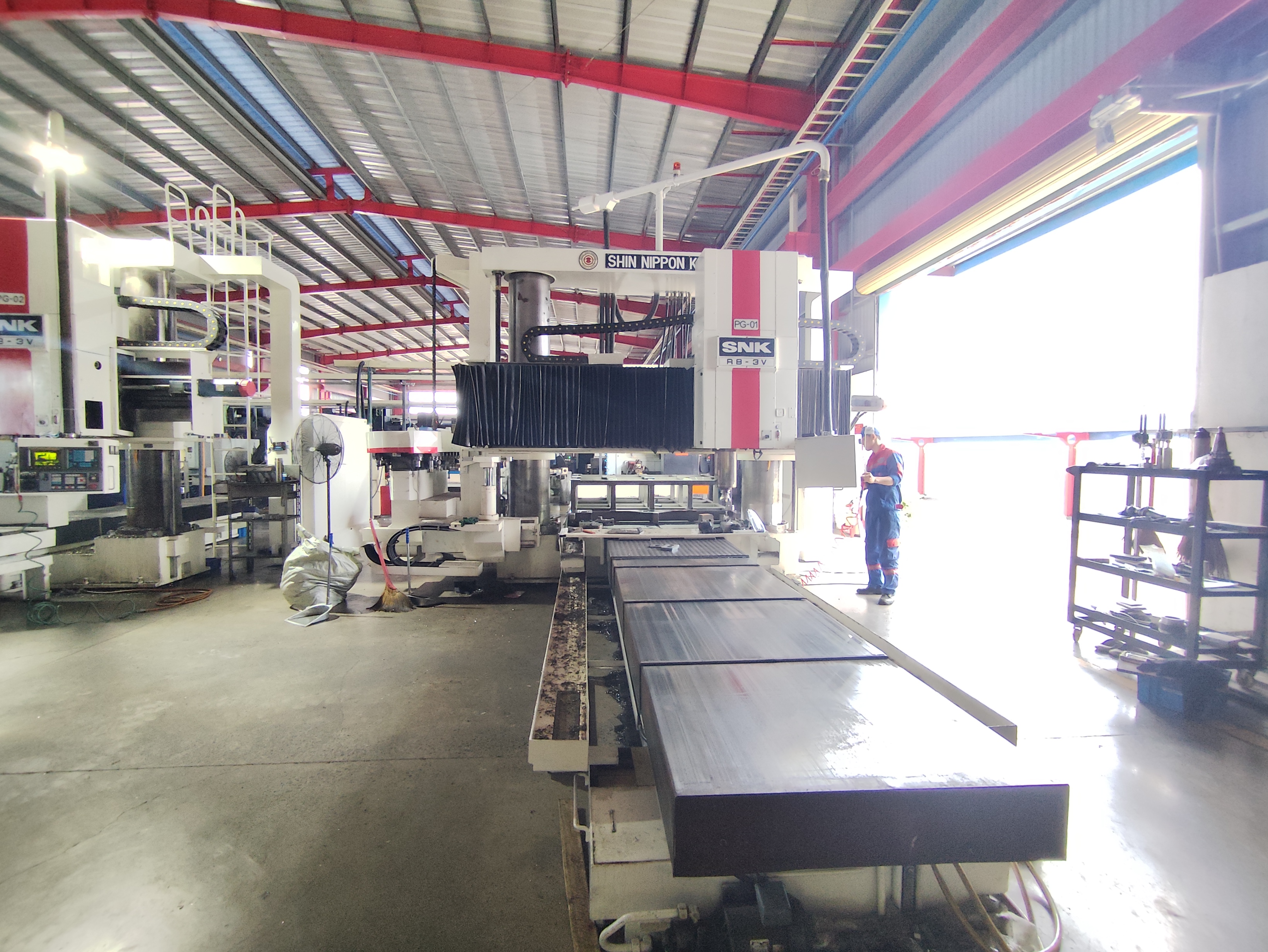
For heavy machinery and aerospace needs, specialized plants operate 5-meter CNC vertical turning centers for single/double-row ball and crossed-roller slewing bearings, alongside 70-set 5-axis CNC machining facilities that process titanium, Inconel, and aluminum aerospace hydraulic valve blocks. Advanced engineering plastic units utilize Class cleanrooms, hot-runner high-temperature injection molding, and multi-axis CNC to process PTFE, PFA, FEP, PEEK, and FFKM seals.
- Powder Metallurgy & MIM: Sintered structural sprockets, oil-impregnated bushings, and 17-4PH/316L MIM components.
- Aerospace 5-Axis CNC: Machining titanium, Inconel, and aluminum hydraulic valve blocks and optical mounts.
- Slewing Bearings: Ø200–5,000 mm ball, three-row roller, and crossed-roller bearings plus enclosed slewing drives.
- Fluoropolymers: Cleanroom-molded PTFE, PFA, FEP, and high-temp PEEK wafer carriers and gears.
Which Quality Inspection Steps Validate Precision Tooling and Turnkey Assemblies?
Quality validation relies on resident engineering teams carrying out DFM reviews, PPAP Level 3 documentation, and ZEISS 3D CMM metrology lab inspections. In-process verification includes surface roughness, contour checking, metallographic grain flow analysis, and salt-spray testing for heavy metal stampings and hydraulic hand pallet truck assemblies.
Engineering coordination incorporates early-stage design for manufacturability (DFM) evaluations, including 2D/3D tolerance stack analysis, mold flow simulation, and progressive die design before cutting tool steel. On the shop floor, resident engineers perform PPAP Level 3 documentation checks, material composition verification, and 50 PPM defect control benchmarking.
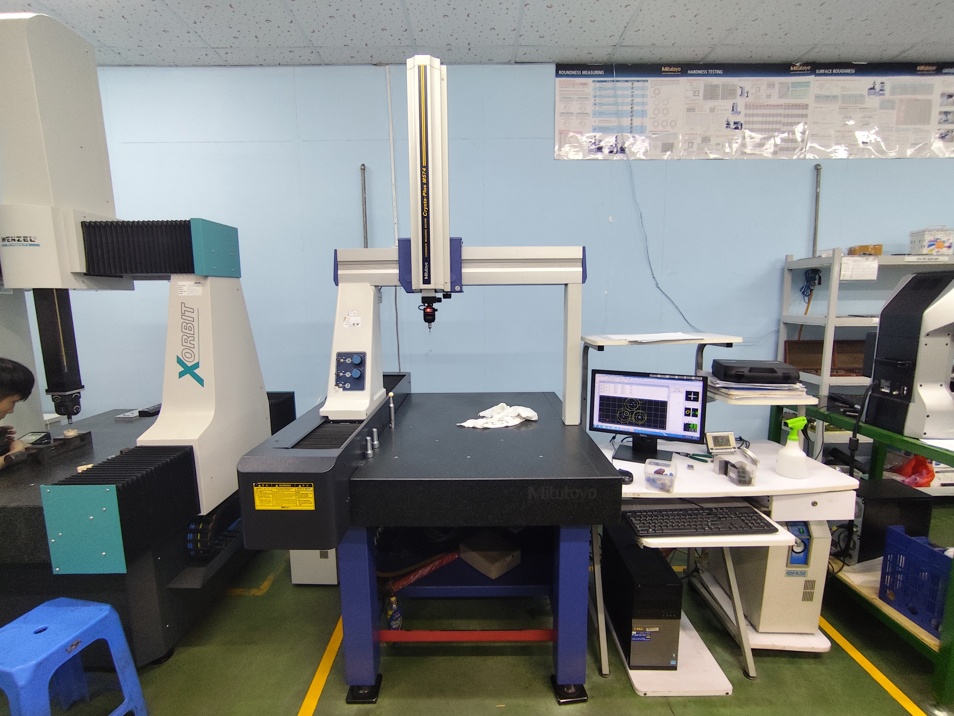
Metrology laboratories utilize ZEISS and Mitutoyo Crysta-Apex S 3D coordinate measuring machines, contour measurement devices, and surface roughness testers to verify microstructural integrity and geometry. Finished assemblies, such as 2.0T to 5.0T hydraulic hand pallet trucks and heavy-duty stamped fire extinguisher brackets, undergo 100% pump hydraulic leak testing, 240-hour ASTM B117 salt spray exposure, and 1,500-hour UV powder coat testing.
- DFM reviews featuring pre-quote 2D/3D tolerance stack analysis and mold flow modeling.
- Metrology analysis using ZEISS 3D CMM, contour measurement, and metallographic density checking.
- Assembly verification for hand pallet trucks with 100% leak testing of AC/DF cast-iron pumps.
- Environmental testing of stamped brackets with 240+ hour ASTM B117 salt spray and UV coating checks.
Precision Manufacturing & Sourcing Specification Matrix
| Technical Dimension | Standard Commercial Grade | High-Precision OEM Export Grade | DEWIN Verification Protocol |
|---|---|---|---|
| Machining & Forming Tolerance | ISO 2768-m (±0.10 mm nominal) | ISO 2768-f (±0.01 mm – ±0.025 mm critical bores) | Calibrated 3D CMM & Air/Pin Gauging |
| Surface Roughness & Finish | Ra 1.6 – 3.2 µm as-machined / standard coat | Ra 0.4 – 0.8 µm precision ground / MIL-A-8625 anodized | Profilometer & Coating Thickness Gauge |
| Material & Alloy Certification | Supplier Mill Test Report (MTR) | Independent OES chemical & mechanical verification | EN 10204 3.1 + RoHS/REACH Compliance |
| Batch Inspection & Packaging | ISO 2859-1 (AQL 1.0 Major / 2.5 Minor) | Zero-defect critical features + VCI export crating | Pre-Shipment Inspection (PSI) Report |
Frequently Asked Questions
How is DFM tolerance analysis conducted before tooling production begins?
Engineers perform pre-quote 2D and 3D tolerance stack analyses, progressive die simulations, and mold flow modeling prior to cutting steel, ensuring drawing specifications match production tooling parameters.
What inspection equipment verifies dimensional accuracy for high-precision components?
Metrology labs employ ZEISS and Mitutoyo Crysta-Apex S 3D coordinate measuring machines, contour meters, microstructural analysis tools, and surface roughness testers to confirm geometric tolerances.
What processes are used to fabricate heavy-duty stamped and welded bracket assemblies?
Factories deploy progressive stamping presses up to 315 tons, laser cutting tools, and OTC/Panasonic robotic MIG/TIG welding cells to construct SPCC and SS304 steel brackets engineered for 5G vibration resistance.
How are powder metallurgy parts processed for shock absorber and transmission applications?
Iron, copper, and stainless steel powders are compacted on automatic CNC presses from 15 to 500 tons, followed by mesh-belt or vacuum sintering, steam treatment, and oil impregnation for self-lubricating bronze bushings.