What surface hardening and heat treatment processes extend the service life of precision shafts?
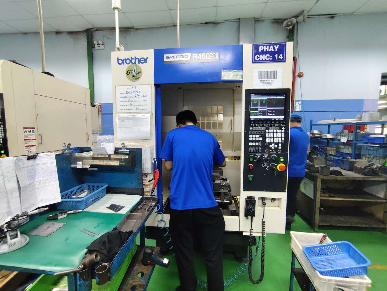
Precision shafts achieve high wear resistance through CQI-9 controlled carbonitriding continuous furnaces and liquid quenching, establishing an HRC 58–62 surface hardness and 0.85–1.25 mm case depth. Forgings undergo saponification, phosphating, and controlled normalizing before 136 robotic CNC lathes and 4 German EMAG hard-turning cells complete finished concentric geometries.
Key Takeaways
- Precision shafts and CV joint components achieve HRC 58–62 case hardness with a 0.85–1.25 mm case depth using CQI-9 controlled continuous furnace carbonitriding and hard turning.
- Sintered structural gears and transmission sprockets utilize powder metallurgy presses from 15T to 500T paired with mesh-belt sintering and steam-treatment furnaces.
- Forming dies and stamped assemblies leverage DFM 2D/3D tolerance simulation, progressive die tooling, and surface treatments such as saponification, phosphating, or MoS2 liners.
High-stress transmission shafts, CV joint star-shaped sleeves (#68-3 to #125), core shafts, and trunnion brackets rely on tightly controlled surface conversion and thermal processing to withstand cyclic fatigue and friction. Initial billet preparation incorporates raw steel bar cutting, isothermal annealing, shot blasting, and saponification with phosphating to prepare materials for 160T to 630T closed-die precision cold and warm forging. Controlled normalizing ensures uniform ferrite-pearlite grain flow before spline features are machined.
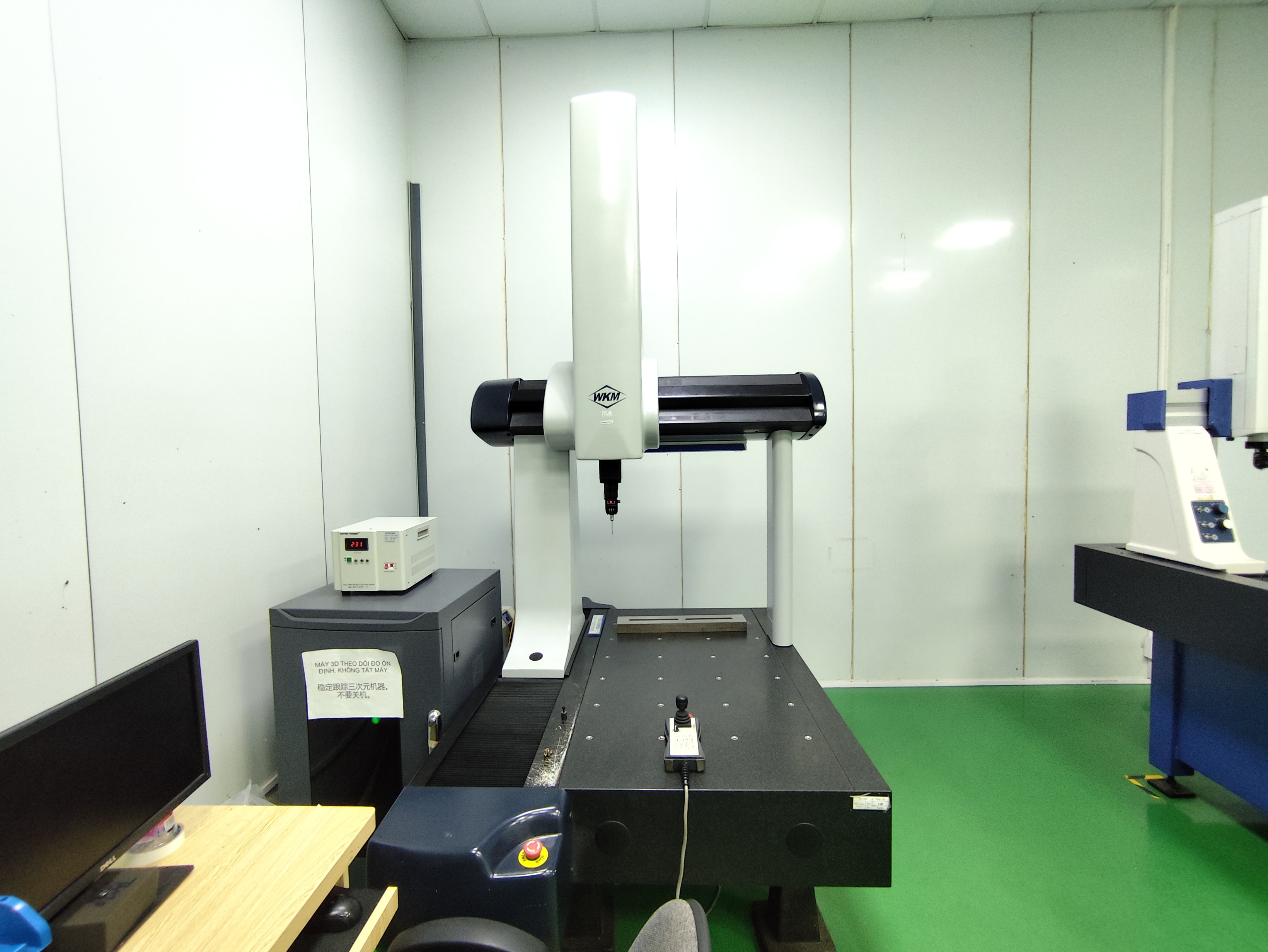
Final wear resistance is established in continuous heat-treatment furnaces meeting CQI-9 carbonitriding specifications. Hardened raceways and internal splines hold ±0.008 mm concentricity and pitch tolerances compliant with DIN 5480 and JIS B 1603 standards. Quality verification includes 100% eddy-current crack sorting, magnetic particle inspection, ultrasonic cleaning, and 3D metrology using ZEISS and Mitutoyo Crysta-Apex S coordinate measuring machines.
- CQI-9 continuous furnace carbonitriding establishing HRC 58–62 case hardness and 0.85–1.25 mm depth
- 160T–630T closed-die precision cold and warm forging with controlled normalizing
- High-speed hydraulic pull broaching holding ±0.008 mm spline pitch tolerances
- 100% eddy-current crack sorting, magnetic particle inspection, and ultrasonic cleaning
Which manufacturing and finishing methods optimize wear resistance for precision gears?
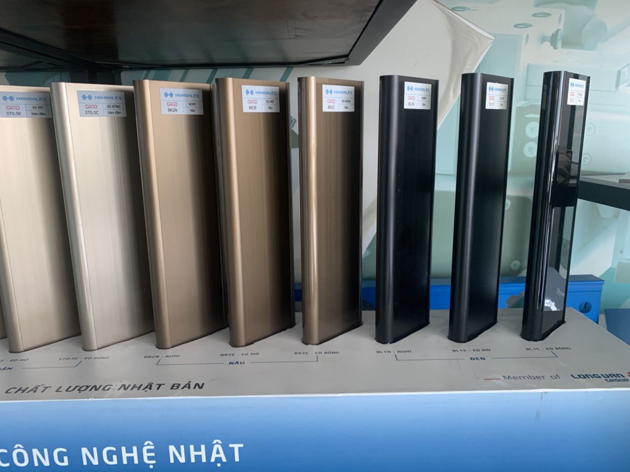
Precision structural gears and sprockets use powder metallurgy processes with 15T to 500T automatic CNC powder presses, mesh-belt sintering, and steam-treatment furnaces. Higher-density transmission components undergo vacuum sintering, CNC gear hobbing, shaping, and medium-frequency induction hardening to ensure microstructural integrity and dimensional accuracy across operations.
Sintered gears, oil pump rotors, and shock absorber pistons fabricated via powder metallurgy (PM) and metal injection molding (MIM) obtain density and surface durability through controlled high-temperature sintering. Automated mechanical and hydraulic presses ranging from 5T to 680T compact iron, copper, and stainless steel (such as 304, 316L, and 17-4PH) powders into high-density green compacts. Sintering in mesh-belt or vacuum furnaces bonded with steam-treatment sealed pores and generates a protective oxide layer that mitigates abrasive wear.
For large-diameter slewing ring gears (Ø200 mm to Ø5,000 mm), teeth are shaped or hobbed on 5-meter CNC vertical turning centers followed by targeted medium-frequency induction hardening. Surface treatments such as MoS2 phosphating further decrease friction coefficients on dynamic contact interfaces. Gear quality is validated on universal gear profile testers, metallographic microstructure labs, and ZEISS 3D CMM equipment.
- 15T to 500T automatic CNC powder presses paired with mesh-belt sintering and steam treatment
- Vacuum sintering for high-density 304 and 316L stainless steel structural gears and sprockets
- Medium-frequency induction hardening for large-diameter CNC hobbed and shaped gear teeth
- Universal gear profile testing, metallographic density verification, and ZEISS CMM metrology
How do DFM review and surface preparation enhance wear life on forming dies and progressive tooling?
Pre-quote DFM engineering evaluates 2D and 3D tolerance stacks, mold flow, and progressive die designs before cutting steel. Forming dies utilize closed-die forging blanks, high-tonnage progressive presses up to 315T, MoS2 phosphating, and saponification surface preparation to manage friction, material flow, and tooling wear during high-volume production runs.
Tooling life during high-speed cold extrusion, warm forging, and progressive sheet metal stamping depends on rigorous engineering pre-planning and surface lubrication. Dolphin Services® technical teams conduct pre-quote DFM reviews, evaluating drawing tolerances and progressive die designs across 33 stamping presses up to 315T. In-house EDM mold rooms utilize slow-wire EDM and multi-axis CNC centers to craft die components.
During forming operations, pre-treatments such as saponification and phosphating create barrier coatings on raw stock, reducing die galling and tool wear under high pressure. Spherical plain bearings and die sliding components incorporate bonded maintenance-free PTFE fabric liners or MoS2 phosphating treatments to eliminate direct metal-to-metal binding during heavy cyclic press operations.
- Pre-quote 2D and 3D tolerance stack analysis and progressive die DFM simulation
- High-tonnage progressive stamping up to 315T paired with slow-wire EDM mold room fabrication
- Surface preparation including saponification, MoS2 phosphating, and phosphating lines
- In-process ZEISS CMM metrology and 100% dimensional inspection reports
Precision Manufacturing & Sourcing Specification Matrix
| Technical Dimension | Standard Commercial Grade | High-Precision OEM Export Grade | DEWIN Verification Protocol |
|---|---|---|---|
| Machining & Forming Tolerance | ISO 2768-m (±0.10 mm nominal) | ISO 2768-f (±0.01 mm – ±0.025 mm critical bores) | Calibrated 3D CMM & Air/Pin Gauging |
| Surface Roughness & Finish | Ra 1.6 – 3.2 µm as-machined / standard coat | Ra 0.4 – 0.8 µm precision ground / MIL-A-8625 anodized | Profilometer & Coating Thickness Gauge |
| Material & Alloy Certification | Supplier Mill Test Report (MTR) | Independent OES chemical & mechanical verification | EN 10204 3.1 + RoHS/REACH Compliance |
| Batch Inspection & Packaging | ISO 2859-1 (AQL 1.0 Major / 2.5 Minor) | Zero-defect critical features + VCI export crating | Pre-Shipment Inspection (PSI) Report |
Frequently Asked Questions
How is surface hardness and case depth verified for carbonitride-treated shafts?
Case depth and hardness are verified through metallographic microstructure analysis, Rockwell hardness testing targeting HRC 58–62 across a 0.85–1.25 mm case depth, and 100% non-destructive eddy-current sorting for micro-cracks.
What quality control standards govern heat-treated precision components across Asian production hubs?
Production facilities operate under IATF 16949:2016 automotive standards, AS9100D aerospace requirements, CQI-9 heat-treat guidelines, and ISO 9001:2015 quality management systems backed by ZEISS 3D CMM inspection.
What lead times and engineering steps apply to custom progressive die tooling?
Custom progressive die tooling typically requires 15 to 20 days for fabrication. The engineering workflow includes initial 2D drawing intake, pre-quote DFM tolerance analysis, CAD simulation, slow-wire EDM machining, and FAI metrology verification.