Sheet Metal Design Tips: 8 Guidelines for Manufacturable Parts
February 12, 2025 · 8 min read
Sheet metal fabrication is one of the most widely used manufacturing processes in the world — from server chassis and electrical enclosures to automotive brackets and HVAC components. The process is fast, scalable, and cost-effective, but only when parts are designed with manufacturing constraints in mind. These eight guidelines will help you create sheet metal parts that are easier to fabricate, more consistent in quality, and cheaper to produce.
The most cost-effective sheet metal parts respect the fabricator's real constraints: a minimum bend radius near one material thickness, holes kept at least 2.5× thickness away from bends, standard 90° angles, and realistic ±0.25–0.5 mm bend tolerances rather than machining-grade precision.

Top Stainless Steel Pipe Manufacturer in Vietnam
Watch on YouTube
Real footage from an audited DEWIN partner factory in Vietnam.
1. Choose the Right Material and Thickness
Material selection drives everything: bend behavior, weldability, corrosion resistance, and cost. For general enclosures, cold-rolled steel (SPCC) or galvanized steel offers a good balance of strength and economy. Stainless steel (SUS304, SUS316) is the standard for corrosion-prone environments. Aluminum (5052, 6061) is preferred when weight matters. Common gauges range from 0.5 mm to 3 mm — thinner sheets bend easily but may lack rigidity, while thicker stock requires larger bend radii and higher tonnage presses.
For most enclosures, cold-rolled or galvanized steel balances strength and cost; stainless (SUS304/316) suits corrosion-prone use, and aluminum (5052/6061) saves weight. Common gauges run 0.5–3 mm — thinner bends easily but flexes, while thicker stock needs larger radii and more press tonnage.
2. Respect Minimum Bend Radii
Every material has a minimum internal bend radius below which cracking occurs. As a starting rule, use a minimum bend radius equal to the sheet thickness for ductile materials (mild steel, aluminum). For stainless steel and harder alloys, use 1.5–2× the thickness. Bending perpendicular to the rolling direction is stronger — if your part has bends in multiple directions, orient the most critical bend across the grain.
3. Keep Holes Away from Bends
Holes and cutouts placed too close to a bend line will deform during the bending operation. The minimum distance from the edge of a hole to a bend line should be at least 2.5× the material thickness plus the bend radius. This ensures the hole remains round and dimensionally accurate after forming. If a hole absolutely must be near a bend, punch it after bending — but this adds a secondary operation and cost.
4. Use Standard Bend Angles
Brake press tooling is optimized for standard angles — 90° is the most common and cheapest. Acute bends (less than 90°) require specialized tooling and are harder to hold tolerance on. Obtuse bends are feasible but check with your fabricator on available tooling. Wherever possible, design around 90° bends to minimize tooling cost and maximize dimensional consistency.
5. Add Bend Relief Cuts
When a bend terminates at an edge or intersects another feature, the material can tear or deform unpredictably. Bend relief cuts — small rectangular notches at the ends of bend lines — allow the metal to fold cleanly without distorting adjacent features. The relief width should equal the material thickness, and the relief length should extend slightly beyond the bend radius.
6. Design for Flat Pattern Efficiency
Sheet metal parts start as flat blanks cut from standard-sized sheets (typically 1220 × 2440 mm or 1000 × 2000 mm). Parts that nest efficiently on a sheet minimize scrap and reduce material cost. Avoid oddly shaped flanges or asymmetric profiles that waste material. If you're ordering in volume, ask your fabricator to optimize the nesting layout — a few millimeters of adjustment can save significant material over thousands of parts.
7. Specify Realistic Tolerances
Sheet metal is not CNC machining. Standard bending tolerances are typically ±0.25–0.5 mm for dimensions affected by bends. Punched hole positions hold ±0.1 mm. Over-tolerancing drives up cost because it forces slower production, additional inspection, and higher reject rates. Specify tight tolerances only on critical mating surfaces and let non-functional dimensions float within standard fabrication tolerances.
8. Plan Hardware and Joining Early
Many sheet metal assemblies require PEM inserts (press-fit nuts, standoffs, studs), spot welds, or rivet joints. These features need to be designed in from the start — not added as afterthoughts. PEM hardware requires specific hole diameters and minimum edge distances. Spot welds need flange overlap of at least 3× material thickness. Planning these details early avoids redesign cycles and keeps tooling costs under control.
Vietnam's Sheet Metal Fabrication Advantage
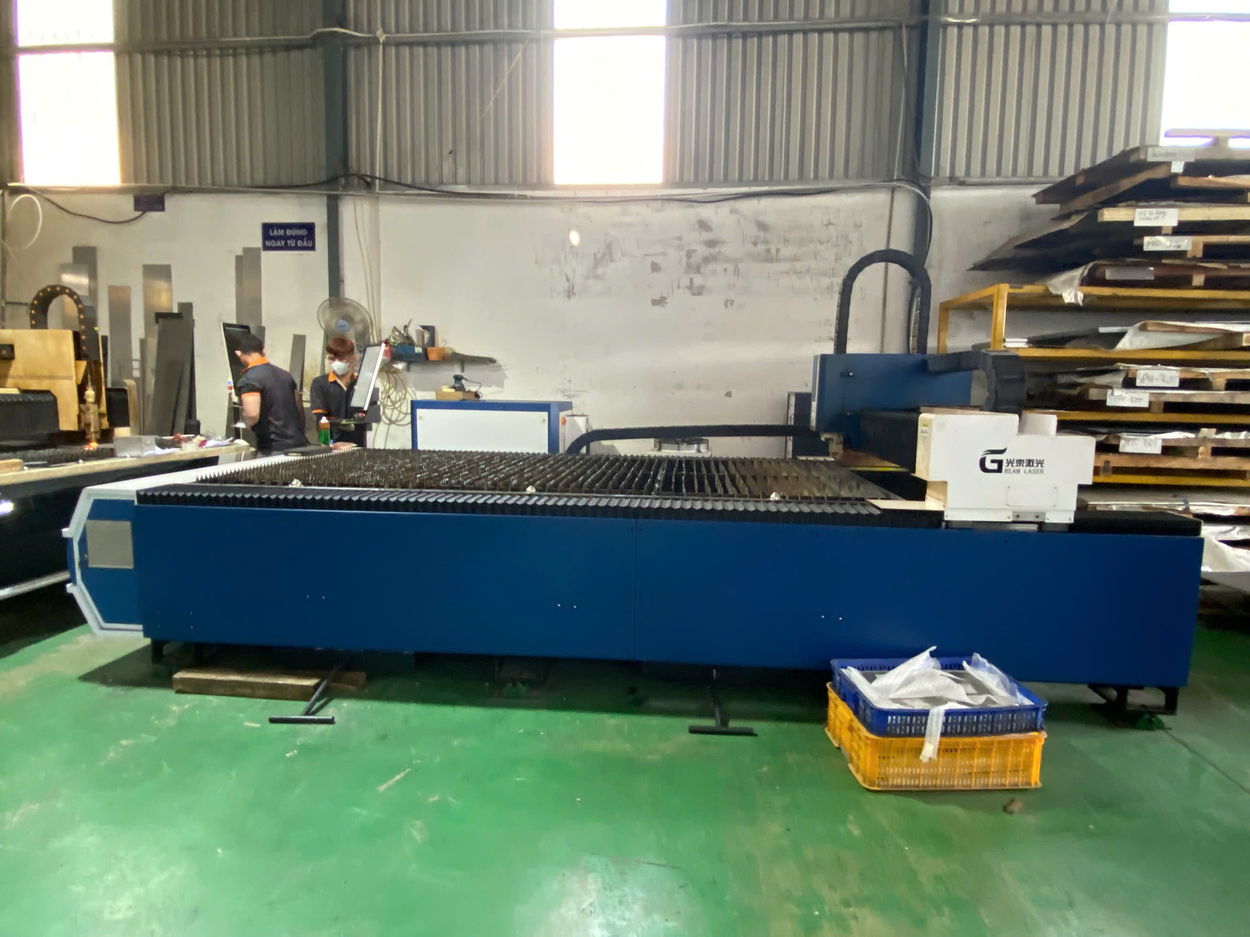
Vietnam has rapidly built capacity in precision sheet metal fabrication, with modern CNC laser cutters, automated press brakes, and powder coating lines now standard at top-tier facilities. Labor costs remain 40–60% lower than China for comparable quality, and many Vietnamese fabricators hold ISO 9001 and ISO 14001 certifications. For US and European buyers, Vietnam offers a compelling combination of precision capability, cost efficiency, and supply chain diversification away from China.
Sourcing Sheet Metal Parts from Vietnam?
DEWIN works with certified sheet metal fabrication facilities throughout Vietnam — from prototyping through volume production. Request a quote →
Frequently Asked Questions
What if my design needs a hole closer to a bend than allowed?
Punching the hole after bending is the standard workaround when a hole cannot sit at least 2.5× the material thickness plus the bend radius away from the bend line. The hole stays round and dimensionally accurate, but the operation is added after forming, so it costs more than punching flat.
What standard sheet sizes should I design my flat pattern around?
Standard sheet stock is typically 1220 × 2440 mm or 1000 × 2000 mm, and flat patterns that nest efficiently on those sizes cut material cost. Avoid oddly shaped flanges and asymmetric profiles that waste stock. On volume orders, ask the fabricator to optimize the nesting layout — a few millimeters saves significant material over thousands of parts.
What do PEM inserts and spot welds require from the design?
PEM hardware needs specific hole diameters and minimum edge distances, and spot welds need flange overlap of at least 3× material thickness. Both have to be designed in from the start rather than added later — retrofitting them forces redesign cycles and pushes tooling costs up.