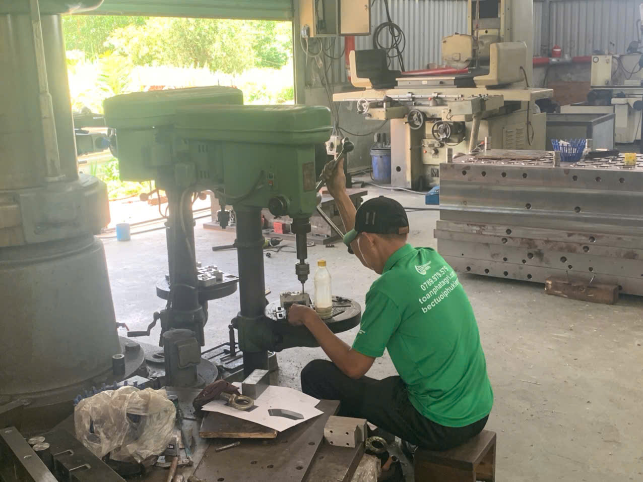
Machining is not only a technical means of transforming raw materials into complex parts but also the foundation of modern engineering. Different machining techniques can accurately remove materials according to design requirements, thus shaping components that range from simple to complex.
Turning
Turning is a basic machining technique that utilizes the rotation of the workpiece and the linear motion of one or more cutting tools to remove materials. This process is particularly suitable for producing symmetrically shaped parts, such as shafts or rollers. With its simplicity and efficiency, turning is widely used in various manufacturing environments and is an indispensable part of mechanical processing. 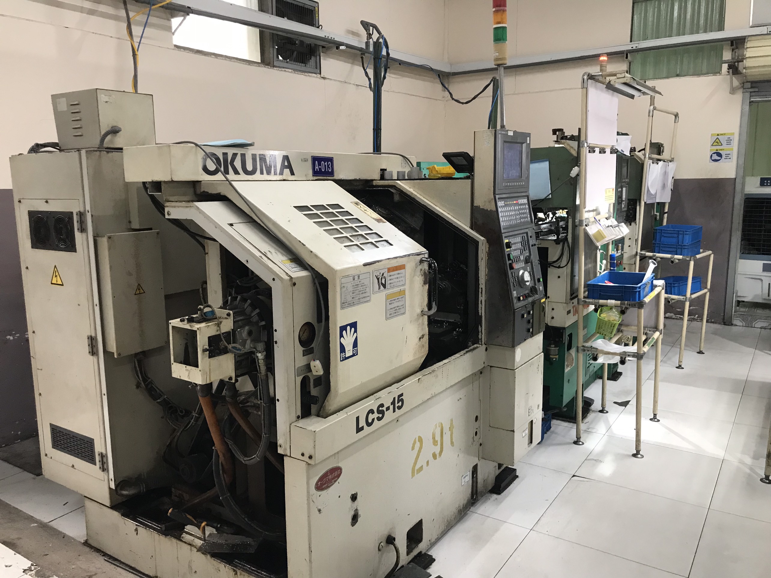
Milling
Unlike turning, the workpiece remains stationary during milling, while the cutting tool rotates at high speed and moves along multiple axes to cut the material. Milling technology is unparalleled in its ability to generate various complex shapes, from simple planes and grooves to complex three-dimensional surfaces and concave-convex shapes, all of which can be achieved through milling. With the development of computer numerical control (CNC) technology, the accuracy and complexity of milling have reached new heights.
Drilling and Grinding
Drilling and grinding address two common manufacturing needs: perforation and surface finishing. Drilling holes using a rotating drill bit to create holes in the material is an ideal choice for making through holes or blind holes. The grinding process uses abrasive wheels for precise surface finishing, which can produce extremely smooth surfaces on hard materials and is suitable for applications that require high surface quality.
Summary
Machining technology is the cornerstone of manufacturing, and its development and innovation directly drive the boundaries of industrial design and the improvement of manufacturing efficiency. From turning to laser cutting, each technology has its unique application scenarios and advantages, and engineers can carefully choose the appropriate processing technology according to product requirements.
Thank you for reading our article. If you need related products or have any questions or suggestions about our products, please don’t hesitate to contact us by sending an email, and we will reply to your email as soon as possible.

Precision Manufacturing & Sourcing Specification Matrix
| Technical Dimension | Standard Commercial Grade | High-Precision OEM Export Grade | DEWIN Verification Protocol |
|---|---|---|---|
| Machining & Forming Tolerance | ISO 2768-m (±0.10 mm nominal) | ISO 2768-f (±0.01 mm – ±0.025 mm critical bores) | Calibrated 3D CMM & Air/Pin Gauging |
| Surface Roughness & Finish | Ra 1.6 – 3.2 µm as-machined / standard coat | Ra 0.4 – 0.8 µm precision ground / MIL-A-8625 anodized | Profilometer & Coating Thickness Gauge |
| Material & Alloy Certification | Supplier Mill Test Report (MTR) | Independent OES chemical & mechanical verification | EN 10204 3.1 + RoHS/REACH Compliance |
| Batch Inspection & Packaging | ISO 2859-1 (AQL 1.0 Major / 2.5 Minor) | Zero-defect critical features + VCI export crating | Pre-Shipment Inspection (PSI) Report |
Frequently Asked Questions
What engineering files are required to quote understand different machining processes with DEWIN?
Provide 3D CAD models (STEP or IGES) along with 2D engineering drawings (PDF/DXF) specifying critical-to-quality (CTQ) tolerances, material grade, surface finish, and annual volume.
How does DEWIN verify dimensional accuracy and material compliance before shipment?
Every production lot undergoes incoming material spectrometer verification (EN 10204 3.1), First Article Inspection (FAI) via 2D/3D coordinate measuring machines (CMM), and AQL pre-shipment audits.
Can DEWIN support both low-volume prototype validation and mass production scaling in Vietnam and China?
Yes. DEWIN coordinates rapid CNC and bridge-tooling prototypes alongside high-tonnage production tooling across audited ISO 9001 and IATF 16949 partner factories in Vietnam and China.