
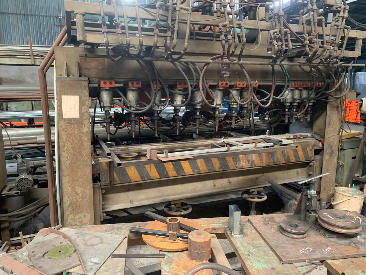
A recurring problem we encounter when auditing supplier welds on custom sheet metal parts is fatigue cracking 1 — often invisible until a part fails in service.
Yes, welded joints are significantly more susceptible to fatigue failure than the base metal in sheet metal fabrication. Stress concentration at the weld toe, residual tensile stresses from thermal cycling, and microscopic defects like porosity or incomplete fusion all drastically reduce fatigue life under cyclic loading conditions.
This is not a theoretical concern. Over 80% of structural failures in engineering trace back to fatigue, and the majority start at the weld rather than the parent material sheet metal fabrication 2. For purchasing managers sourcing custom sheet metal assemblies, understanding why welds fail and how to prevent it can save significant costs and protect end-user safety. The sections below break down design strategies, inspection standards, joining alternatives, and quality process controls that address this issue head-on.
How can I design my sheet metal assemblies to reduce the risk of fatigue at the weld joints?
Last year, a client's mounting bracket kept cracking after three months of service cyclic loading conditions 3. The root cause was not the material or the welder's skill — it was the joint geometry itself, which created a severe stress concentration 4 right where the cyclic load peaked.
To reduce fatigue risk at weld joints, design assemblies with smooth geometric transitions, full-penetration butt welds in primary load paths, tapered thickness changes, and generous fillet radii. Avoid abrupt weld toe angles and place welds away from areas of maximum stress concentration.
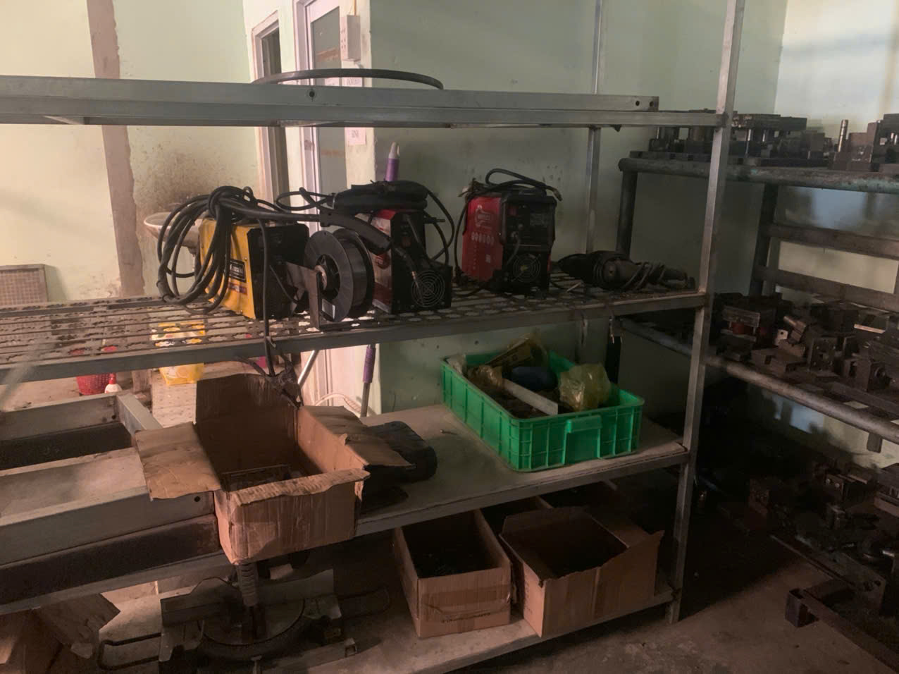
Why Geometry Matters More Than Material
A common misconception is that using a higher-strength steel or aluminum alloy will automatically improve fatigue performance in welded assemblies. In reality, fatigue life in welded joints often does not scale with the tensile strength of the parent metal. The dominant factor is geometry — specifically, the shape and abruptness of the weld toe. A well-executed fillet weld can still produce a local stress concentration factor of 2 to 5 times the nominal stress. That means even a perfectly welded joint can become the weakest link if the design forces stress into a sharp geometric transition.
When our engineering team reviews client drawings before production starts, we flag several common design risks. Here is a quick reference:
| Design Feature | Fatigue Risk Level | Recommended Action |
|---|---|---|
| Sharp weld toe angle (< 30°) | High | Specify a minimum toe angle of 45° or use toe grinding |
| Abrupt thickness change at joint | High | Taper the transition at a 1:4 slope or gentler |
| Fillet weld in primary load path | Medium–High | Switch to full-penetration butt weld where possible |
| Weld placed at peak stress location | High | Relocate weld to a lower-stress region |
| Smooth, ground weld cap with gradual transition | Low | Maintain as standard practice |
Full Penetration vs. Partial Penetration
For thin sheet metal parts — typically under 3 mm — achieving full weld penetration is challenging. Burn-through is a real risk. Yet partial penetration welds leave an unfused root that acts as a pre-existing crack notch. In our experience exporting assemblies to US-based OEMs, we push suppliers to use controlled heat input parameters and backing strips where feasible. This avoids the root gap problem while keeping sheet metal distortion to a minimum. Understanding how thin and thick plate processing differ is critical when selecting the right welding approach for different gauge materials.
The Role of Residual Stress in Design
Even with perfect geometry, welding residual stress can approach the material's yield strength. This effectively means the joint is already "pre-loaded" in tension before any external force is applied. Design mitigation includes specifying post-weld treatment such as stress relief annealing for critical parts, or mechanical treatments like shot peening that introduce beneficial compressive stresses at the weld toe surface.
Practical Tip: Use FEA Before Committing to a Design
We routinely advise clients to run Finite Element Analysis 5 on their assemblies before we lock in the manufacturing process. The "hot spot method" in FEA lets us predict localized stress at the weld toe. A 10% stress difference in that zone can change fatigue life by a factor of two or more. Catching this at the design stage is far cheaper than dealing with field failures.
What specific inspection standards should I require from my supplier to detect potential weld fatigue?
During a recent supplier audit at a Vietnamese facility, we discovered that their incoming weld inspection was limited to a quick visual check. There was no protocol for detecting subsurface flaws — the very defects that seed fatigue cracks months or years later.
Require suppliers to follow ISO 5817 (weld quality levels), ISO 17640 (ultrasonic testing), and ISO 10042 for aluminum welds. At a minimum, demand visual inspection per AWS D1.1, dye penetrant testing for surface cracks, and radiographic or ultrasonic testing for full-penetration welds in fatigue-critical applications.
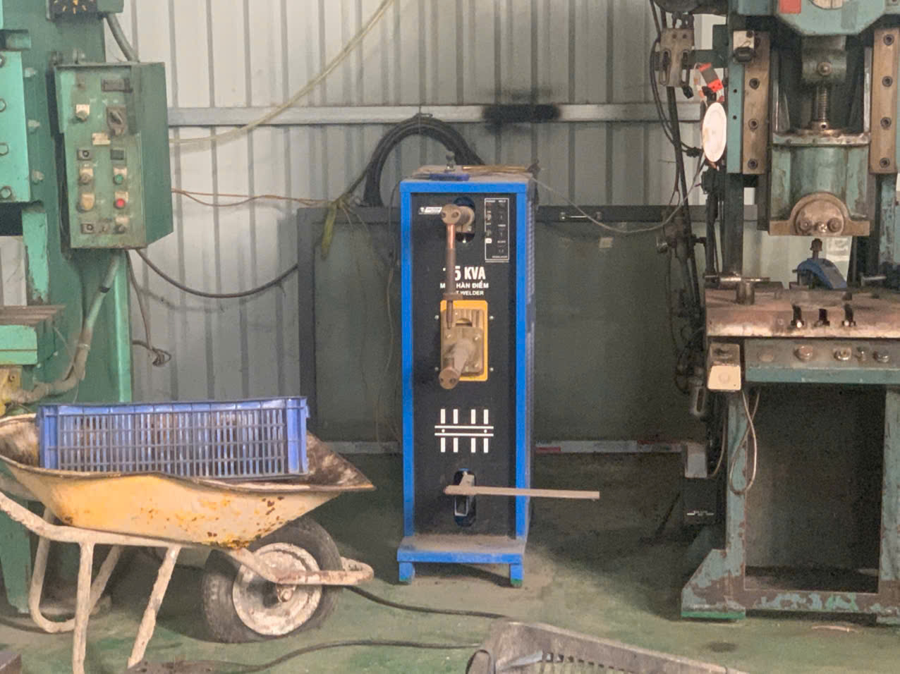
Matching Inspection Method to Defect Type
Not all weld defects are equal from a fatigue standpoint. Porosity deep inside a weld is less dangerous than an undercut or lack of fusion at the weld toe, because the toe is where the stress concentration peaks. The inspection method must match the defect type you are trying to catch.
| Defect Type | Fatigue Impact | Best Detection Method |
|---|---|---|
| Surface-breaking crack at weld toe | Critical | Dye penetrant testing (DPT) or magnetic particle inspection (MPI) |
| Subsurface porosity | Moderate | Radiographic testing (RT) |
| Incomplete root fusion | Critical | Ultrasonic testing 6 (UT) or RT |
| Undercut at weld toe | High | Visual inspection with weld gauge |
| Misalignment / angular distortion | High | Dimensional inspection with CMM or fixture gauges |
| Slag inclusions | Moderate | RT or UT |
Setting Acceptance Criteria
Specifying an inspection method without a clear acceptance level is meaningless. ISO 5817 7 defines three quality levels for steel and nickel welds: B (stringent), C (intermediate), and D (moderate). For parts subject to cyclic loading, we always recommend Level B. This sets tight limits on undercut depth, excess weld metal, and angular misalignment — all factors that directly influence fatigue crack initiation. For a deeper look at the international welding standards that apply to sheet metal fabrication, understanding these quality levels is essential.
For aluminum sheet metal assemblies, ISO 10042 provides equivalent quality levels. Aluminum is particularly sensitive because the heat affected zone in alloys like AA5083 or AA1050 softens during welding, reducing local hardness and ductility. This makes the HAZ itself a potential fatigue failure site, in addition to the weld toe.
In-Process vs. Final Inspection
Relying solely on final inspection is a mistake. By the time a part reaches the end of the line, a subsurface crack is already locked in. We structure our quality control to include in-process monitoring — checking welding current, voltage, and travel speed against qualified parameters during production. This is part of the process control philosophy that our US clients expect and that prevents the rework loops that inflate costs and delay delivery.
Digital Twin and In-Situ Monitoring
A trend we are watching closely is the use of real-time sensor data and digital twin technology to monitor weld quality as it happens. While this is still emerging in contract manufacturing environments, some of our advanced suppliers in Vietnam are beginning to pilot thermal imaging during welding to flag hot spots that could indicate excessive residual stress or incomplete fusion.
Is welding the most reliable joining method for my custom parts under constant vibration?
One trade-off we weigh repeatedly with clients is whether welding is truly the best choice for their application. A protective housing that sits in a server rack faces very different loads than a mounting bracket on a diesel generator. The answer depends on the vibration profile, the material, and the cost tolerance.
Welding is not always the most reliable joining method for parts under constant vibration. Mechanical fastening, adhesive bonding, and hybrid joining methods can outperform welded joints in fatigue resistance by avoiding the stress concentrations, residual stresses, and heat affected zone damage that welding inherently introduces.
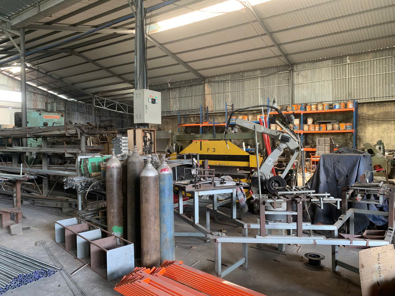
Comparing Joining Methods for Cyclic Loading
The fatigue performance of a joint depends on how it handles repeated stress cycles. Welding creates a metallurgical bond, but it also introduces the highest level of residual stress and geometric discontinuity. Riveting and bolting distribute load through bearing contact and can be designed to allow controlled slip, which actually dissipates vibration energy. Adhesive bonding spreads stress over a large area, eliminating point-source stress concentrations entirely.
| Joining Method | Stress Concentration | Residual Stress | Fatigue Life (Relative) | Best Application |
|---|---|---|---|---|
| Full-penetration butt weld | Medium | High | Moderate | Structural load paths, sealed enclosures |
| Fillet weld | High | High | Low–Moderate | Non-critical brackets, stiffeners |
| Riveting | Low–Medium | Negligible | High | Aerospace skins, vibration-prone panels |
| Bolting | Low (with proper preload) | Negligible | High | Serviceable joints, heavy assemblies |
| Adhesive bonding | Very Low | Negligible | High (for shear loads) | Thin panels, dissimilar metals |
| Hybrid (weld + adhesive) | Low–Medium | Moderate | High | High-performance automotive, aerospace |
When Welding Still Wins
Welding remains the best option when you need a fully sealed joint, when disassembly is never required, or when the assembly must withstand high static loads in addition to moderate vibration. For many custom sheet metal enclosures we produce for US clients, welding is non-negotiable because the part must be watertight or gas-tight.
When to Consider Alternatives
If your parts experience high-cycle fatigue — millions of load cycles at moderate amplitude — the S-N curves for welded joints show a clear disadvantage compared to bolted or bonded joints. This is especially true for thin-gauge aluminum, where the heat affected zone significantly weakens the material adjacent to the weld. These are among the key factors that affect the service life of sheet metal fabrication products.
Explosion-welded transition joints are another emerging option for dissimilar metal sheet assemblies. They bypass the fusion zone entirely, creating a solid-state bond that avoids the microstructural changes and residual tensile stresses of conventional welding. We have seen growing interest in this technology from clients working with aluminum-to-steel transitions.
Variable Amplitude Loading Considerations
Real-world vibration is rarely a simple constant-amplitude sine wave. Parts on vehicles, generators, or industrial equipment see variable amplitude loading — a mix of large and small stress cycles. Fatigue life prediction under these conditions uses Rainflow cycle counting and Miner's rule to sum damage from each cycle. Welded joints are particularly sensitive here because even small stress cycles can propagate an existing crack once it has initiated at the weld toe. In contrast, bolted joints with proper preload can tolerate a broader spectrum of vibration without initiating cracks.
How do I ensure my contract manufacturer follows the right PPAP steps to prevent fatigue-related failures?
A lesson we learned early in our work with US purchasing managers is that quality cannot be inspected into a part — it must be built in from the process design stage. This is exactly what the Production Part Approval Process 8 (PPAP) is designed to ensure, and it is where most supplier relationships succeed or fail when fatigue performance is at stake.
Ensure your contract manufacturer completes PPAP elements including process flow diagrams, PFMEA covering weld fatigue risks, control plans with in-process weld monitoring, measurement system analysis for inspection tools, and initial sample inspection reports with fatigue-relevant dimensional and NDE data.
PPAP Elements That Matter Most for Fatigue
PPAP includes up to 18 elements, but not all carry equal weight for fatigue prevention. The ones that directly address weld fatigue risk are the process failure mode and effects analysis 9 (PFMEA), the control plan, and the initial sample inspection report (ISIR). Here is how each connects to fatigue:
The PFMEA should identify weld toe geometry, incomplete fusion, and excessive residual stress as potential failure modes. For each, the team must assign severity, occurrence, and detection ratings. If the weld toe angle or undercut depth is not monitored during production, the detection score should be high — meaning the risk is uncontrolled.
The control plan translates the PFMEA into specific checks on the production floor. For fatigue-critical welds, this includes monitoring welding parameters (current, voltage, travel speed, shielding gas flow) and performing periodic dye penetrant or ultrasonic testing on sample parts. We require our suppliers to document these checks with traceable records.
Connecting Fatigue Life Prediction to PPAP
A forward-thinking PPAP includes fatigue life prediction data. If the client has provided cyclic loading requirements — expressed as a target number of cycles at a given stress range — the PPAP package should demonstrate that the weld design and process meet or exceed that target. This can come from FEA simulation, reference to published S-N curves for the joint category, or physical fatigue testing of initial samples.
Common PPAP Gaps We Find During Audits
When our team audits contract manufacturers in Vietnam and across Asia, the most common gaps related to weld fatigue include:
- PFMEA that treats all welds generically, without distinguishing between fatigue-critical and non-critical joints.
- Control plans that specify visual inspection only, missing subsurface defect detection methods.
- No documented welding procedure specification (WPS) or procedure qualification record (PQR).
- No measurement system analysis for weld gauges or NDE equipment.
- Missing records of post-weld treatment when specified on the drawing.
Each of these gaps introduces uncontrolled variation into the process — the exact condition that leads to fatigue failures in the field.
Why "Right First Time" Matters for Fatigue
Fatigue damage is cumulative and irreversible. If a batch of parts ships with marginal weld quality — slightly too much undercut, slightly too high residual stress — those parts will fail earlier than expected. There is no rework that can fully restore the fatigue resistance of a compromised weld. This is why our clients value the "right first time" philosophy. The PPAP process, executed with discipline, is the mechanism that makes it happen.
Conclusion
Welded joints are indeed the most fatigue-vulnerable points in sheet metal assemblies. Smart design, rigorous inspection, careful joining method selection, and disciplined PPAP execution are your best defenses against costly field failures.
Frequently Asked Questions
How can I design my sheet metal assemblies to reduce the risk of fatigue at the weld joints?
Last year, a client's mounting bracket kept cracking after three months of service cyclic loading conditions 3 . The root cause was not the material or the welder's skill — it was the joint geometry itself, which created a severe stress concentration 4 right where the cyclic load peaked.
What specific inspection standards should I require from my supplier to detect potential weld fatigue?
During a recent supplier audit at a Vietnamese facility, we discovered that their incoming weld inspection was limited to a quick visual check. There was no protocol for detecting subsurface flaws — the very defects that seed fatigue cracks months or years later.
Is welding the most reliable joining method for my custom parts under constant vibration?
One trade-off we weigh repeatedly with clients is whether welding is truly the best choice for their application. A protective housing that sits in a server rack faces very different loads than a mounting bracket on a diesel generator. The answer depends on the vibration profile, the material, and the cost tolerance.
Footnotes
1. Replaced HTTP 404 with an authoritative Wikipedia page defining fatigue (material) which includes fatigue cracking. ↩︎
2. Provides a comprehensive overview of sheet metal fabrication processes and applications. ↩︎
3. Replaced HTTP unknown with an academic source (NJIT) explaining cyclic loading in the context of design for fatigue. The content is relevant and authoritative. ↩︎
4. Defines stress concentration, its causes, and its impact on material failure. ↩︎
5. Replaced HTTP unknown with an authoritative Wikipedia page defining Finite Element Method, which is the basis for Finite Element Analysis. ↩︎
6. Describes ultrasonic testing as an NDT method for detecting flaws in welds and materials. ↩︎
7. Official ISO page for the standard defining quality levels for fusion-welded joints. ↩︎
8. AIAG’s official resource for PPAP, outlining its purpose and importance in manufacturing. ↩︎
9. Provides a detailed introduction to PFMEA, its methodology, and its role in risk identification. ↩︎