

Allowable burr height 1 for stamping parts trips up many buyers I work with optical comparators 2. One rejected shipment over a sharp edge can stall an entire assembly line and wreck your delivery schedule.
The allowable burr height for stamping parts is typically 10% of sheet thickness as a general rule, but most production drawings specify 0.05 mm to 0.15 mm. Safety-critical automotive and aerospace parts often require burrs below 0.10 mm or even 0.05 mm.
That range is wide for a reason. The right limit depends on your part’s function, material, and industry. Let me walk you through how to set it correctly.
How Do I Determine the Right Burr Height Tolerance for My Stamping Parts?
A few years back, our team in Vietnam reviewed a bracket drawing that simply said "no burrs." That vague note nearly caused a costly dispute, so we now push clients toward measurable limits.
Determine burr height tolerance by part function first: allow up to 10% of material thickness for noncritical parts, 0.05–0.10 mm for functional or cosmetic parts, and below 0.05 mm for precision or safety-critical components. Material thickness and hardness then refine that starting value.
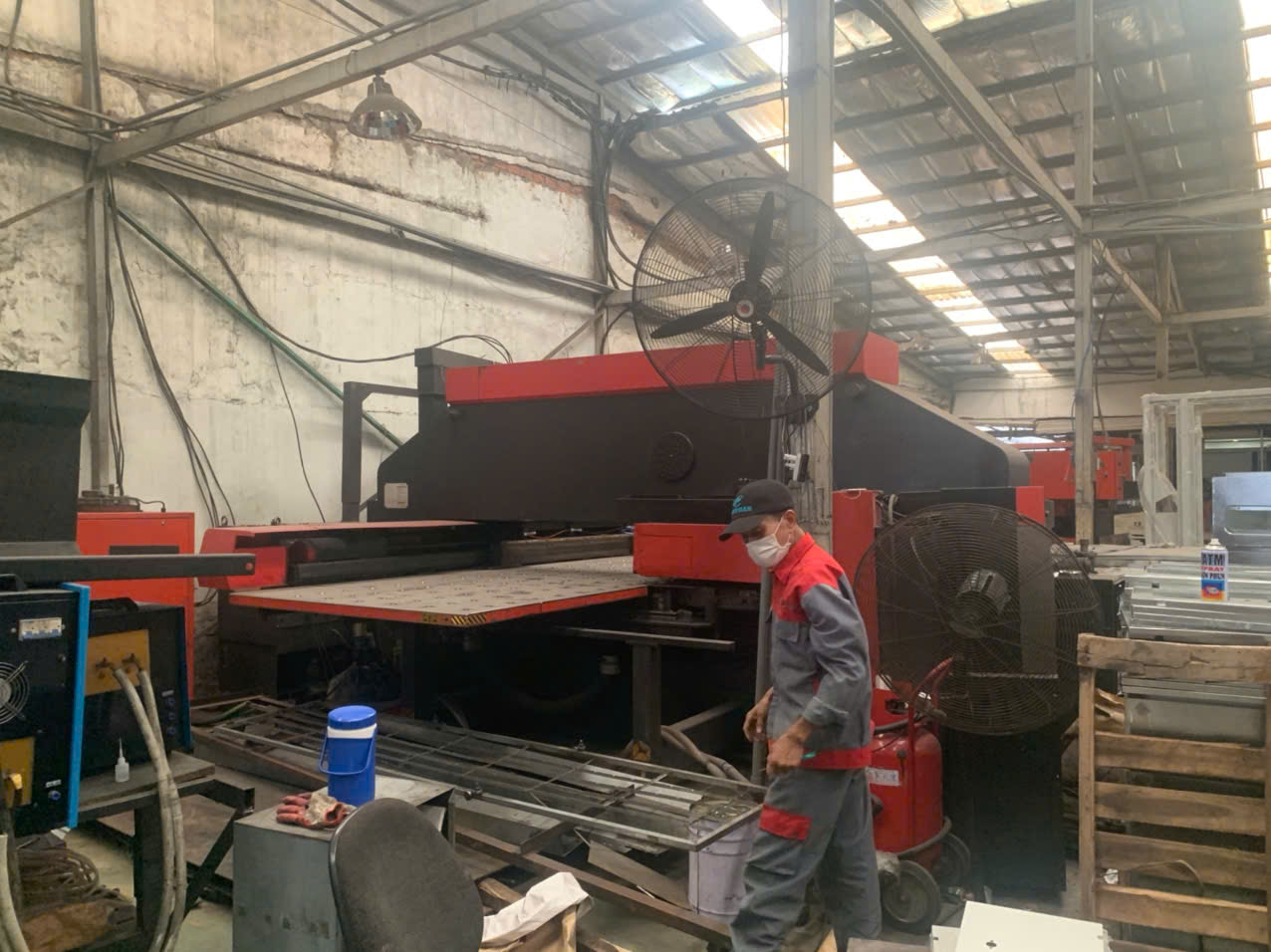
Burr height is the raised sliver of material left on a cut edge after blanking, piercing, or punching. Every stamped part has some burr. The question is never "zero or not." The question is "how much is acceptable for this part's job."
I break the decision into three steps with clients. First, classify the part. Second, check the thickness. Third, adjust for material strength.
Step 1: Classify the Part by Function
A structural clip hidden inside a wall can tolerate a bigger burr than a connector terminal. Here is the framework we apply during drawing reviews:
| Part Category | Typical Allowable Burr Height | Examples |
|---|---|---|
| Noncritical industrial | Up to 10% of thickness (0.2–0.5 mm on thick stock) | Rough brackets, internal supports |
| Standard functional parts | 0.05–0.15 mm | Mounting clips, panel fasteners |
| Automotive functional | 0.05–0.10 mm | Chassis brackets, connector shells |
| Safety-critical / precision | Below 0.05 mm | Brake, fuel, restraint, aerospace parts |
Step 2: Adjust for Sheet Thickness
Thicker material naturally produces larger burrs. A practical thickness-based guideline many of our stamping suppliers 3 follow looks like this:
| Sheet Thickness | Suggested Max Burr Height |
|---|---|
| ≤ 1 mm | ≤ 0.05 mm |
| 1–2 mm | ≤ 0.08 mm |
| 2–3 mm | ≤ 0.10 mm |
| > 3 mm | ≤ 0.15 mm |
Step 3: Adjust for Material Strength
Higher tensile strength 4 materials shear differently. As strength goes up, the allowable burr should often drop below the simple 10% rule. Hardened steel edges fracture cleaner but any burr left is sharper and more dangerous. Softer metals like aluminum and copper smear more, so slightly higher burrs may be tolerated if function allows.
What Standards Should I Reference When Setting Burr Height Limits?
When we audit stamping suppliers across Vietnam and Taiwan, the first thing I check is whether their inspection plans reference a real standard or just tribal knowledge. The difference shows up fast in consistency.
Reference DIN 9830 and NF E81-010 for burr height limits and measurement methods on stamped parts. These standards define acceptable burr classes by thickness and application, and they recommend specifying limits on the drawing by agreement rather than relying on generic rules of thumb.

Old shop rules travel by word of mouth. Standards travel on paper. That matters when your supplier is on another continent and your inspector needs an objective pass/fail criterion.
The Two Standards Worth Knowing
DIN 9830 5 is a German standard covering burr height on stamped parts. It links acceptable burr classes to material thickness and cutting method. NF E81-010 is the French counterpart. It goes further by addressing how burr height should be measured, not just what the limit is. That measurement clause is valuable. I have seen two inspectors measure the same edge and get different numbers because one included rollover and the other did not.
Standards Versus Rules of Thumb
Here is how the two approaches compare in practice:
| Aspect | 10% Rule of Thumb | Standards-Based Spec (DIN 9830 / NF E81-010) |
|---|---|---|
| Basis | Thickness only | Thickness, function, cutting method |
| Measurement method | Undefined | Defined or agreed |
| Dispute resolution | Weak | Strong, contractual |
| Best use | Early design estimates | Production drawings and PPAP |
What to Put on the Drawing
A good drawing note does four things. It states the maximum burr height in millimeters. It identifies which edges the limit applies to. It specifies the burr direction, because the burr side and the rollover side behave differently in assembly. And it names the measurement method or standard. In our PPAP submissions, we treat burr height as a measurable characteristic with recorded data, not a visual judgment call.
Industry also layers its own requirements on top. Automotive programs often specify 0.05–0.10 mm for functional parts. Aerospace and precision electronics frequently demand below 0.05 mm. Welding and sealing surfaces get their own tighter callouts because a burr breaks the fit-up.
How Can I Verify That My Supplier Controls Burr Height Consistently During Production?
One trade-off I weigh constantly for clients is audit depth versus speed. A quick sample check tells you about today's parts. Only process evidence tells you about next month's shipment.
Verify burr height control by auditing punch-to-die clearance records, die maintenance and sharpening schedules, and in-process measurement data using micrometers or optical comparators. Consistent suppliers track burr height across production runs and resharpen tooling before burrs drift out of tolerance.

Burr height is a leading indicator of tool health. When a punch dulls, burrs grow. So a supplier who measures burrs regularly is really monitoring their tooling. A supplier who never measures burrs is flying blind, and you will find out the hard way.
What Drives Burr Formation
Punch-to-die clearance 6 is the primary factor. Optimal clearance varies by material: roughly 5–10% of thickness per side for mild steel, 8–12% for aluminum, and 4–8% for stainless steel. Too much clearance drags material and creates tall burrs. Too little accelerates tool wear, which also grows burrs over time. Ask your supplier how they set clearance for your specific material. A vague answer is a red flag.
The Audit Checklist I Use
When our engineers visit a stamping plant, we look for five things:
- Clearance documentation. Die design records showing clearance calculated for the actual material grade and thickness.
- Tool maintenance schedule. Sharpening intervals defined by hit count or measured burr height, not by "when parts look bad."
- In-process measurement. Burr checks at first article, at set intervals, and at end of run, recorded on a control chart.
- Proper measurement tools. Micrometers 7, optical comparators, or dedicated burr height gauges. Fingernail checks do not count.
- Reaction plan. A written rule stating what happens when burr height approaches the limit, ideally pulling the die before parts go nonconforming.
Watch the Trend, Not the Snapshot
Burr height climbs gradually as tools wear. A supplier who shows you burr measurements trending over a production run has real control. During process control reviews, I ask for that trend data before final inspection. If the numbers only exist on the day of the audit, they were probably created for the audit.
What Should I Do If My Stamping Parts Exceed the Allowable Burr Height?
A U.S. purchasing manager once called us about a container of clips with edges sharp enough to cut packaging film. We contained the lot, arranged deburring locally, and fixed the die before the next run. That sequence matters.
If stamping parts exceed the allowable burr height, quarantine the lot, then rework parts through deburring, tumbling, or brushing if the design permits. Address the root cause by resharpening tooling or correcting punch-die clearance, and require corrective action evidence before the next production run.

Excessive burrs are not just a cosmetic issue. They cause real downstream failures. Burrs interfere with welding fit-up and bonding. They lift plating and paint, creating corrosion starting points. They cut handlers' hands. On press-fit assemblies, they jam clearances. And on dynamically loaded parts, a burr acts as a stress concentration point that can seed a fatigue crack under cyclic load.
Short-Term Fix: Rework Options
Not every rework method suits every part. Here is how the common options compare:
| Rework Method | Best For | Watch Out For |
|---|---|---|
| Vibratory tumbling | Small parts in volume | Can round edges and dent thin flanges |
| Mass finishing | Batches needing uniform edges | Media lodging in holes and slots |
| Brushing / belt deburring | Flat parts, accessible edges | Misses internal hole edges |
| Manual edge cleanup | Low volume, critical edges | Slow, costly, operator-dependent |
Confirm the rework does not violate other requirements. Tumbling can alter surface finish. Deburring can change hole edge condition needed for fastener seating. We always get client sign-off on the rework method before touching a nonconforming lot.
Long-Term Fix: Root Cause
Rework treats the symptom. The cause is almost always tooling. Dull punches, worn die sections, or incorrect clearance for the material. Require your supplier to show the resharpening record and a first-article burr measurement from the corrected die. Then add burr height to the ongoing inspection plan so drift gets caught early. In our experience managing final inspection for U.S. clients, one documented corrective action cycle usually prevents the problem from repeating, because the supplier now knows the characteristic is being watched.
Conclusion
There is no single allowable burr height for stamping parts. Start at 10% of thickness, tighten by function and standard, and verify your supplier's tooling control. That is how we keep every lot right the first time.
Frequently Asked Questions
How Do I Determine the Right Burr Height Tolerance for My Stamping Parts?
A few years back, our team in Vietnam reviewed a bracket drawing that simply said "no burrs." That vague note nearly caused a costly dispute, so we now push clients toward measurable limits.
What Standards Should I Reference When Setting Burr Height Limits?
When we audit stamping suppliers across Vietnam and Taiwan, the first thing I check is whether their inspection plans reference a real standard or just tribal knowledge. The difference shows up fast in consistency.
How Can I Verify That My Supplier Controls Burr Height Consistently During Production?
One trade-off I weigh constantly for clients is audit depth versus speed. A quick sample check tells you about today's parts. Only process evidence tells you about next month's shipment.
Footnotes
1. Provides background on burr formation, a core concept underlying the article’s topic. ↩︎
2. ASTM standards govern calibration and use of optical comparators for dimensional inspection. ↩︎
3. Alibaba.com is a major platform connecting buyers with global stamping suppliers for sourcing audits. ↩︎
4. Background on the material property that governs how metals shear during stamping. ↩︎
5. DIN is the official standards body that publishes DIN 9830 defining burr classes on stamped parts. ↩︎
6. ASME publishes engineering standards relevant to tooling clearance in metal stamping processes. ↩︎
7. Explains the precision measurement instrument used to verify burr height dimensions. ↩︎