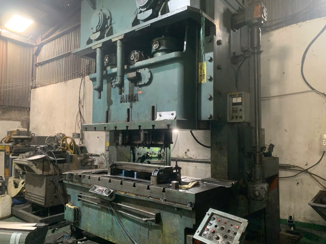
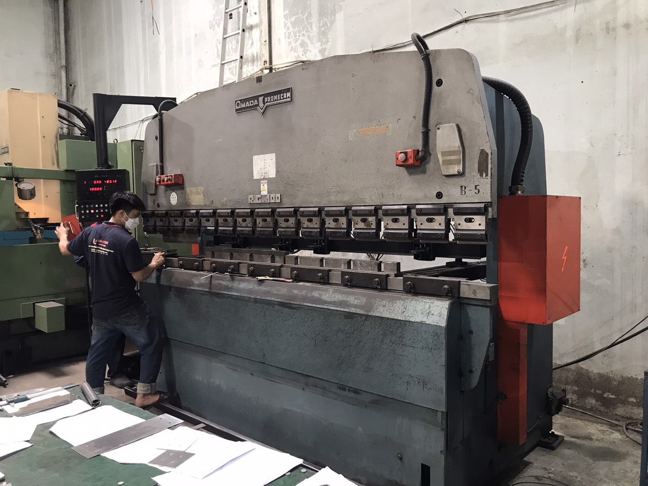
Springback in stamped parts bending nearly derailed one of our first bracket projects. The parts looked perfect off the press, yet failed the customer’s angle gauge every single time.
Springback in stamped parts bending is caused by elastic recovery: when the press force is released, the elastic portion of the deformation rebounds, so the bend angle opens slightly. High-strength materials, large bend radii, thin sheets, and excessive die clearance all amplify this effect.
That is the short answer. But if you buy or design stamped parts, you need more detail. Let me walk you through prediction, material selection, die compensation, and inspection.
How can I predict springback before I finalize my stamping tool design?
During a co-development project for a US client, our tooling engineers in Vietnam ran forming simulations 1 before cutting any steel. That single step saved us two rounds of die rework.
You can predict springback by combining forming simulation software, the material's yield strength-to-elastic modulus ratio, the R/t ratio of the bend, and physical trial bends on actual coil samples. Simulation gives a first estimate; trial bending on production material confirms the real compensation value.

Prediction is where most springback problems are won or lost. In my experience managing custom parts projects across Vietnam and China, teams that skip prediction end up paying for it in tooling rework. Here is how I break the prediction process down.
Start with the physics, not the software
Springback follows a simple logic. During bending, the outer surface stretches and the inner surface compresses. Part of that strain is plastic and permanent. Part of it is elastic. When the punch retracts, the elastic strain releases and the part rebounds. So any prediction method is really estimating one thing: how much elastic energy remains in the bend after unloading.
Three practical prediction methods
- Analytical estimation. Use the yield strength divided by Young's modulus 2, multiplied by the R/t ratio. A higher result means more springback. This gives a rough angle correction before any tooling exists.
- Forming simulation. Modern FEA tools 3 model the loading and unloading cycle. They handle complex geometry, sidewall curl, and twist far better than hand calculations.
- Physical trial bends. Nothing beats bending strips cut from the actual production coil. We always request mill certificates 4 and run trial bends before tool sign-off.
| Prediction Method | Accuracy | Cost | Best Used For |
|---|---|---|---|
| Analytical (rule of thumb) | Low to moderate | Very low | Early quoting and feasibility |
| FEA forming simulation | High | Moderate | Complex parts, AHSS, tight tolerances |
| Trial bends on real coil | Highest for that batch | Low per test | Final tool compensation values |
One warning from our project files: simulation is only as good as the material card you feed it. If the supplier inputs generic mild steel data but the actual coil is a higher-strength grade, the prediction will miss badly. We insist on matching simulation inputs to certified coil properties.
What material properties should I check to reduce springback in my bent parts?
A buyer once asked me why identical brackets from two coils of the "same" steel grade bent differently. The answer sat in the mill certificates: a 12% difference in yield strength.
Check yield strength, tensile strength, Young's modulus, strain-hardening exponent, sheet thickness, and rolling direction. Materials with a high yield strength-to-modulus ratio, such as AHSS, stainless steel, and aluminum, spring back far more than low-carbon mild steel of the same thickness.
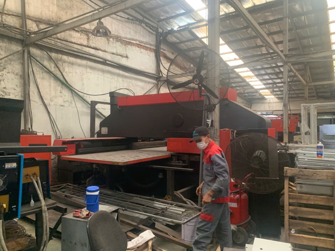
Material choice often dominates springback behavior, more than tooling ever will. When we source stamped brackets and clips for US clients, we review material specifications before we ever discuss die design. Here are the properties that matter most.
The key ratio: yield strength over elastic modulus
This ratio is the single best indicator of springback risk. Higher yield strength means the material resists permanent deformation, so more of the bend stays elastic. Lower modulus means the material rebounds more easily during unloading. Both push springback up.
| Material | Relative Yield/Modulus Ratio | Springback Tendency |
|---|---|---|
| Low-carbon mild steel | Low | Low, predictable |
| Galvanized steel (commercial grade) | Low to moderate | Low to moderate |
| Stainless steel 301/304 | Moderate to high | High |
| Aluminum 5052 / 6061 | High (low modulus) | High |
| AHSS / DP steels | Very high | Very high, plus sidewall curl |
Other properties worth checking
- Thickness. Thinner sheet springs back more. Thicker stock is stiffer and holds its shape better.
- Strain hardening. Materials that work-harden heavily retain higher internal stress after forming, which increases elastic recovery.
- Anisotropy. Rolling changes grain orientation. A bend parallel to the rolling direction behaves differently from one across it. On critical parts, we specify grain direction on the drawing.
- Temper condition. A full-hard coil behaves nothing like an annealed one, even in the same alloy.
My practical advice: lock the material specification tightly. Specify the grade, temper, thickness tolerance, and acceptable yield strength range. Then require mill certificates with every shipment. Loose material specs are the most common hidden cause of springback drift we find during supplier audits.
Which die design adjustments help me compensate for springback in production?
There is a trade-off our tooling partners weigh on every bracket die: coin the bend hard and shorten tool life, or overbend and accept batch sensitivity. Neither option is free.
Compensate for springback by overbending past the target angle, tightening punch-to-die clearance, reducing the punch radius, adding bottoming or coining pressure, and increasing blank holder force to stretch the part. Most production dies combine two or more of these adjustments.

Die compensation is where theory meets the press line. Over years of managing contract manufacturing for stamped mounting clips and brackets, I have seen every one of the following adjustments used, often in combination.
The main compensation techniques
| Adjustment | How It Works | Trade-Off |
|---|---|---|
| Overbending | Bend past the target so recovery lands on the nominal angle | Sensitive to coil-to-coil variation |
| Coining / bottoming | Extra pressure at bottom dead center compresses the bend zone | Higher press tonnage, faster tool wear |
| Tighter die clearance | Controls stress distribution through the thickness | Risk of scoring and galling |
| Smaller punch radius | Increases plastic strain at the bend | Risk of cracking on brittle grades |
| Higher blank holder force | Stretches the sheet, converting elastic strain to plastic | Possible thinning or splits |
| Stepped or curved die faces | Pre-distorts sidewalls to cancel curl and twist | Requires simulation to design |
Choosing the right method for your bending process
The bending method itself sets the baseline. Air bending 5 produces the most springback because the sheet only touches three points. Bottoming reduces it moderately. Coining minimizes it best by inducing compressive stress right at the bend line, but it demands more tonnage and wears tooling faster.
For the zigzag-profile brackets we handle, tool makers usually combine modest overbend with bottoming. For AHSS parts, geometric compensation designed in simulation becomes essential, because sidewall curl and twist cannot be fixed with angle overbend alone.
One more point buyers often miss: servo presses allow real-time force and stroke control. A supplier running servo presses can dial in dynamic compensation that a static mechanical press cannot match. We note press type during every supplier audit for exactly this reason.
How do I verify springback control during supplier quality inspection and PPAP?
Early in our Vietnam operation, a client rejected a shipment of clips that our supplier had passed. The gap? The supplier measured bend angles free-standing, while the client checked them in a constrained fixture. That lesson shaped our inspection protocol.
Verify springback control through PPAP dimensional reports on bend angles and formed heights, check fixtures that simulate assembly conditions, capability studies (Cpk) on critical angles, mill certificates for each coil, and first-article inspection whenever material batch or tooling changes.

Quality verification is where springback stops being an engineering topic and becomes a commercial one. If your supplier cannot demonstrate control, you inherit the risk: rejected lots, line-down events, and expensive air freight for replacements. Here is the verification framework we apply when we run PPAP 6 and final inspection for US clients.
Build springback checks into PPAP
During PPAP, do not accept a dimensional report that only samples one part. Springback varies with coil batch, so we require:
- Dimensional results across multiple parts from the start, middle, and end of the run.
- Capability data (Cpk) on bend angles and formed heights, not just hole positions. Angles are where springback shows up first.
- Material certifications tied to the actual coil used for the PPAP lot, with yield strength recorded.
- A documented reaction plan describing what the supplier does when a new coil shifts the angle.
Use check fixtures, not just protractors
Hand-held angle gauges invite disagreement. A hard check fixture 7 that holds the part the way the assembly will, with go/no-go conditions on the flanges, removes debate. We ask suppliers to build the fixture during tooling, then correlate it with the client's receiving inspection before mass production starts.
Watch for drift, not just first-pass results
Springback control is a moving target. New coils, tool wear, lubrication changes, and even upstream laser-cut edges near the bend line can shift results. We schedule in-process angle checks at set intervals during each run and review the trend data at final inspection. Getting it right the first time is the goal, but staying right across coils is what protects on-time delivery.
Conclusion
Springback comes from elastic recovery, amplified by material strength, thin gauge, and loose tooling. Predict it, specify materials tightly, compensate in the die, and verify through PPAP. That is how stamped parts arrive right the first time.
Frequently Asked Questions
How can I predict springback before I finalize my stamping tool design?
During a co-development project for a US client, our tooling engineers in Vietnam ran forming simulations 1 before cutting any steel. That single step saved us two rounds of die rework.
What material properties should I check to reduce springback in my bent parts?
A buyer once asked me why identical brackets from two coils of the "same" steel grade bent differently. The answer sat in the mill certificates: a 12% difference in yield strength.
Which die design adjustments help me compensate for springback in production?
There is a trade-off our tooling partners weigh on every bracket die: coin the bend hard and shorten tool life, or overbend and accept batch sensitivity. Neither option is free.
Footnotes
1. ASME provides engineering standards and resources on forming simulation used in metal stamping tool design. ↩︎
2. Background reference explaining elastic modulus, a core factor in springback calculations. ↩︎
3. Explains the finite element method underlying forming simulation used to predict springback. ↩︎
4. ASTM International sets material testing standards referenced in mill certificate documentation. ↩︎
5. Background on sheet metal bending methods like air bending referenced in die compensation discussion. ↩︎
6. AIAG is the official body defining PPAP requirements used in supplier quality verification. ↩︎
7. Background reference on fixtures used to verify formed part geometry during inspection. ↩︎