

I once traced a batch of cracked brackets back to a single overlooked detail — the stamping supplier had welded stainless steel to galvanized mild steel, and nobody caught the mismatch until assembly failed at the customer’s plant.
Weld compatibility and material matching in stamping parts requires verifying base metal composition, carbon equivalent, thickness ratios, surface coating sequencing, and joint geometry before welding begins. Upstream design decisions — not welding machine settings — cause most weld failures in stamped assemblies.
This article walks through the exact checks I run on every stamped-and-welded project we manage, from material certification review through final destructive testing. Each section targets a specific failure mode that purchasing managers and engineers encounter when sourcing custom stamped components from Asia.
How Do I Verify Material Compatibility Before Welding Stamped Parts?
A lesson we learned early in our supply chain work: a Vietnam-based supplier once shipped stamped brackets made from two different steel heats. The welds looked fine visually, but pull tests showed the heat-affected zone cracking at half the expected load.
To verify material compatibility before welding stamped parts, check the mill certificate for each heat of steel, confirm the carbon equivalent is below 0.45 for low-carbon grades, match tensile strength between joined materials, and ensure the thermal expansion coefficient difference stays within acceptable limits for the weld process.
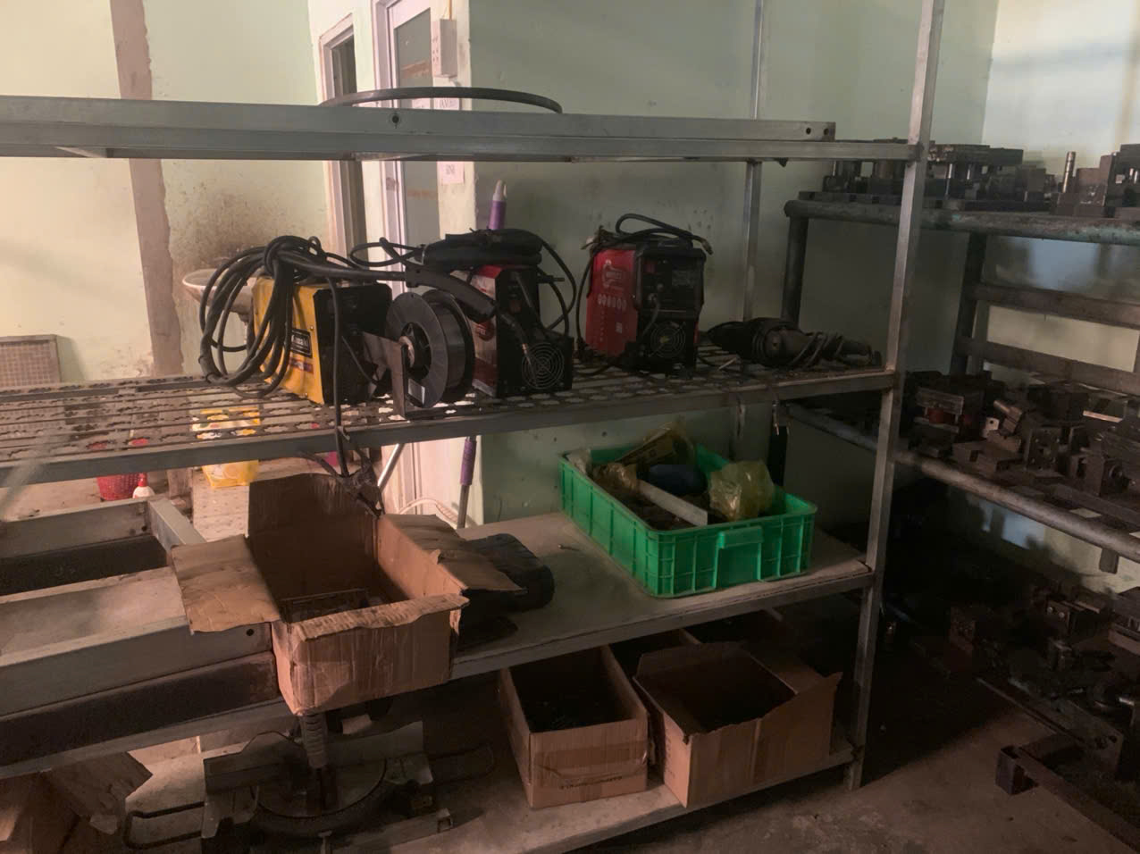
The Golden Rule: Same-to-Same Matching
The simplest rule in metallurgical compatibility is this: weld low-carbon to low-carbon, stainless to stainless, and aluminum to aluminum. Mixing families introduces problems that no amount of parameter tuning can fix.
When you weld stainless steel to galvanized steel, the zinc coating vaporizes. This causes explosive expulsion — molten metal spatters out of the joint. The result is a porous, weak weld that also creates toxic fumes. I have seen purchasing managers specify "steel bracket, welded" without noting the grade on each component. That vagueness is where failures begin.
Carbon Content and Carbon Equivalent
Low-carbon steels like 1008 and 1010 are the easiest to stamp and weld. They flow well in dies, and the heat-affected zone stays soft after welding. But as carbon content rises, hardenability increases. The weld nugget becomes brittle, and cold cracking risk goes up.
The carbon equivalent 1 formula gives you a single number to predict weldability. A value below 0.40 is generally safe for most resistance spot welding 2 and MIG processes without preheat. Between 0.40 and 0.55, you need controlled procedures. Above 0.55, the risk of cracking is high.
| Steel Grade | Carbon Content (%) | Carbon Equivalent (Approx.) | Weldability |
|---|---|---|---|
| 1008 | 0.08 | ~0.10 | Excellent |
| 1010 | 0.10 | ~0.13 | Excellent |
| 1020 | 0.20 | ~0.25 | Good |
| 1045 | 0.45 | ~0.55 | Fair — Preheat needed |
| 4140 | 0.40 | ~0.65 | Poor — Special procedures |
Dissimilar Material Risks
Beyond steel-to-steel combinations, our engineering team evaluates the thermal expansion coefficient when clients request mixed-material assemblies. Aluminum expands at roughly twice the rate of steel. If you weld an aluminum stamping to a steel bracket (through specialized transition joints), the differential expansion during thermal cycling can fatigue the joint in service.
Galvanic corrosion 3 is another hidden threat. When two dissimilar metals sit in contact — especially in humid environments — the less noble metal corrodes preferentially. This matters when a stamped copper-alloy terminal is resistance-welded to a steel bus bar, for example. I always flag these combinations during our design review phase, before die tooling is committed.
What Weld Testing Methods Should I Require From My Stamping Supplier?
During a recent PPAP review 4 for a US-based client, we discovered the stamping supplier had been running pull tests on mild-steel coupons while the actual production parts used HSLA steel. The test results were meaningless.
Require your stamping supplier to perform destructive peel or chisel tests per production lot, cross-section macro examination for weld nugget sizing, and — for advanced high-strength steels — non-destructive evaluation methods because standard pull tests on AHSS can show misleading nugget pull-out failures even on strong welds.

Destructive Testing: The Baseline
Destructive testing remains the standard for resistance spot welding quality control. The two most common methods are the peel test (pulling apart two welded sheets) and the chisel test (driving a chisel into the joint to force separation).
For low-carbon steels, a "button pull" — where the weld nugget tears out of one sheet — indicates a strong weld. But here is the quality control paradox with AHSS: a good AHSS weld can also fail in the nugget because the nugget hardens beyond the base metal strength. It tears through the nugget itself, and visually this looks identical to an undersized, weak weld. This is why our QC team limits welding current and dwell time on AHSS parts to stay within a validated process window, rather than simply maximizing nugget size.
The Role of Self-Tempering in AHSS
Self-tempering 5 is a technique where the welding machine holds current or applies a secondary pulse after the main weld pulse. This keeps heat in the nugget long enough for the martensite to temper slightly, reducing brittleness. We require our suppliers to document the dwell time and post-weld hold parameters on their weld schedule sheets. Without self-tempering, AHSS weld nuggets become glass-hard and crack under impact loads.
Non-Destructive Evaluation (NDE)
For high-volume automotive stamping projects, we are seeing growing adoption of ultrasonic NDE systems that can measure nugget diameter without destroying the part. These systems are not yet universal, but they solve a real problem: you cannot destructively test every part in a 50,000-piece production run.
| Test Method | What It Measures | Best For | Limitation |
|---|---|---|---|
| Peel Test | Nugget pull-out diameter | Low-carbon steel spot welds | Destroys the part |
| Chisel Test | Bond strength at the interface | Quick shop-floor checks | Operator-dependent |
| Cross-Section Macro | Nugget shape, penetration, porosity | Weld qualification / PPAP | Slow, requires metallography lab |
| Ultrasonic NDE | Nugget diameter, internal voids | High-volume production | Equipment cost, calibration needed |
| Hardness Traverse | Hardness across nugget and HAZ | AHSS weld validation | Requires sectioning |
Fixture Datums and Dimensional Control
One detail that many suppliers overlook: define the fixture datums for welding. If the welding fixture locates the assembly on different surfaces than the inspection fixture, your dimensional checks will not correlate. I always ask to see the fixture drawing alongside the weld procedure, and I verify that the datum surfaces match the GD&T callouts on the customer print.
How Can I Avoid Weld Defects Caused by Material Mismatch in Stamped Components?
When we manage contract manufacturing projects, we review the assembly sequence before the first die is cut. I have watched weld defects cascade through an entire production lot simply because the plating was applied at the wrong step.
Avoid weld defects from material mismatch by enforcing a weld-before-plate sequence, keeping zinc plating under 8–12 microns on pre-plated parts, maintaining material thickness ratios between 1:1 and 3:1, stacking parts with burrs facing inward, and removing all stamping lubricants from the weld zone before joining.
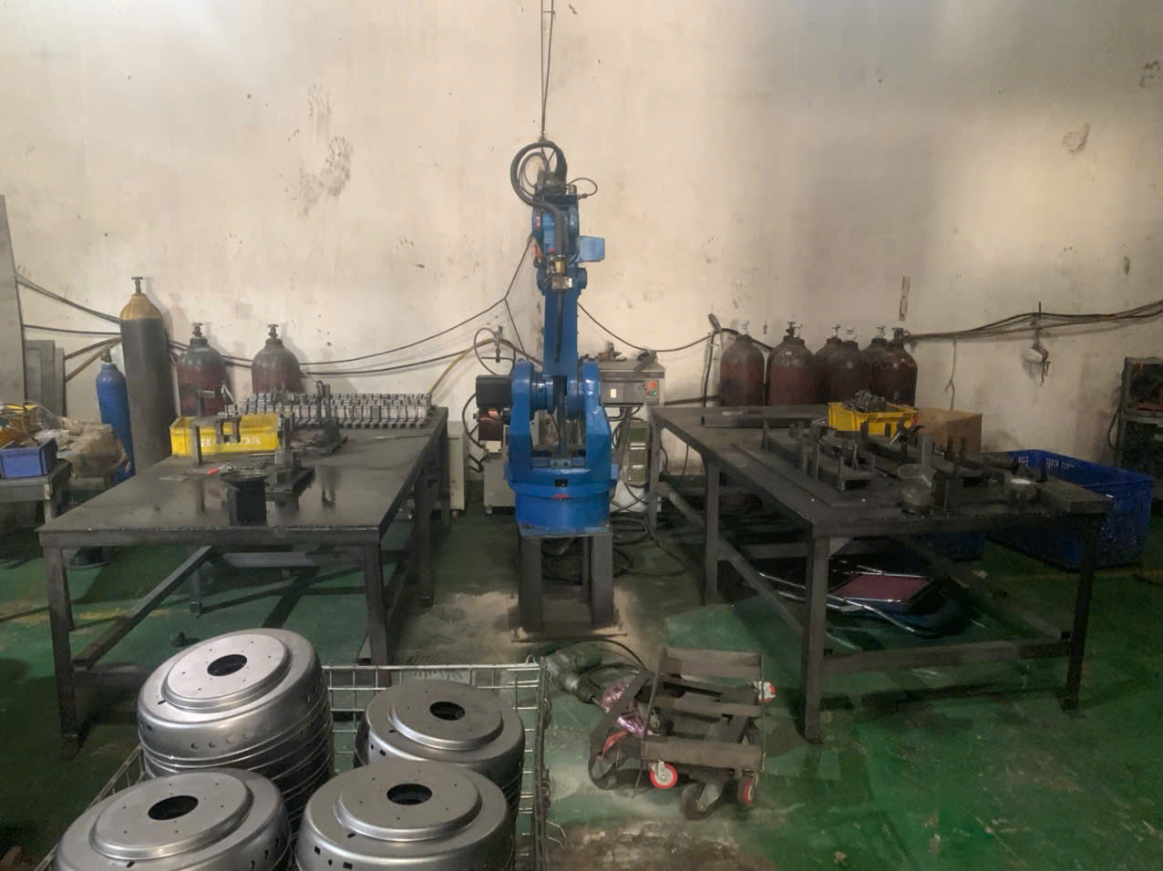
The 12-Micron Rule for Zinc Plating
Zinc plating on stamped parts causes weld expulsion when the coating exceeds 8–12 microns. The zinc vaporizes at welding temperatures, and the expanding gas blows molten metal out of the joint. The result: porous welds, surface spatter, and inconsistent nugget size.
The preferred approach is always weld-before-plate. You stamp the parts, weld the assembly, then send it through zinc plating or powder coating. If the design requires plating before assembly — for example, when internal cavities cannot be reached after welding — the weld zone must be masked during the plating process. This adds cost, but it is the only reliable compromise.
For stainless steel assemblies, the alternative sequence is passivate-after-weld. Passivation does not interfere with the weld joint, so there is no need for masking.
Material Thickness Ratio
The thickness ratio between the two sheets being joined should stay between 1:1 and 3:1. When you weld a 0.5 mm sheet to a 2.0 mm sheet (a 1:4 ratio), the heat concentrates in the thinner sheet. It burns through before the thicker sheet reaches welding temperature. The weld nugget shifts toward the thinner material, reducing penetration into the thicker sheet.
In tailored blank applications — where sheets of different thicknesses are laser-welded before stamping — the weld line itself can shift during forming due to preferential straining of the thinner side. This dimensional shift causes fit problems in the final assembly.
Projection Geometry for Resistance Welding
When stamped parts include formed projections (dimples) for projection welding, the geometry must be tightly controlled:
| Parameter | Specification | Why It Matters |
|---|---|---|
| Projection Diameter | 2–4 mm | Too small = insufficient nugget; too large = inconsistent collapse |
| Projection Height | 0.3–0.8 mm (for 1–2 mm material) | Controls initial contact area and current density |
| Edge Distance | ≥ 2× material thickness | Prevents edge blowout and distortion |
| Burr Direction | Inward (toward mating surface) | Outward burrs interfere with the weld interface and sealing faces |
Stamping Lubricants and Oxides
Stamping lubricants, drawing oils, and surface oxides are invisible enemies of weld quality. They decompose under the arc or resistance heat and release gases that become trapped as porosity inside the weld. Our standard process requires solvent cleaning or vapor degreasing of all weld zones before joining. This is a simple step, but I have seen suppliers skip it to save five minutes per batch — and then spend days reworking failed welds.
Springback and Residual Stress
Stamped parts carry residual stresses from the forming process. When you apply welding heat, those stresses relax — and the part moves. This "springback release" can shift the part by several tenths of a millimeter, enough to take a precision bracket out of tolerance. Light alloys like aluminum and magnesium show even more springback due to their lower elastic modulus. Our approach is to use thermomechanical simulation during the design phase to predict these shifts and compensate the die geometry accordingly.
Grain Flow Interaction
The stamping process creates directional grain flow in the metal. When the weld pool forms across this grain flow, the fusion line can become a weak point for fatigue. In high-cycle fatigue applications — like engine brackets or suspension mounts — we orient the weld line parallel to the primary load direction wherever possible. This aligns the stamping-induced grain structure with the weld, reducing the risk of premature fatigue cracking at the fusion boundary.
Which Certifications Should I Request to Confirm Weld and Material Quality Control?
One trade-off I weigh on every project is how much documentation to require versus how much it adds to the part cost. Over-specifying paperwork on a simple bracket wastes money. Under-specifying it on a safety-critical weldment is dangerous.
Request ISO 9001 as a baseline, IATF 16949 for automotive stamping, mill test certificates per ASTM or EN standards for every heat of material, weld procedure specifications (WPS) with qualified procedure qualification records (PQR), and — for advanced high-strength steels — non-destructive evaluation methods because standard pull tests on AHSS can show misleading nugget pull-out failures even on strong welds.

The Certification Stack
Not every project needs the same level of certification. Here is how I tier the requirements based on application:
For general industrial hardware — brackets, mounts, enclosure components — ISO 9001 7 and material certificates are usually sufficient. For automotive-destined stamped weldments, IATF 16949 8 is non-negotiable because it mandates the PPAP process, control plans, and FMEA documentation that catch weld compatibility issues during the planning phase, not during production.
For aerospace or military applications, you may need additional certifications like NADCAP for special processes, or compliance with specific AMS or AWS welding standards.
What to Look for in Mill Certificates
A mill certificate (also called a mill test report 9 or MTR) confirms the chemical composition and mechanical properties of the steel. I check these specific items:
- Carbon content and carbon equivalent
- Tensile strength and yield strength
- Elongation at break
- Heat number traceability
If filler metal is used (MIG welding, for example), the filler metal selection must also come with its own certification. The filler must match or exceed the base metal composition in tensile strength. Using an ER70S-6 filler wire on a 100 ksi AHSS base metal, for instance, would create an undermatched joint that fails under design loads.
Control Plans and Process Audits
When our team conducts supplier audits in Vietnam or other Asian manufacturing hubs, we specifically review the weld control plan. This document should list:
- Weld process type (resistance spot welding, MIG, laser)
- Parameters (current, time, pressure/force, or voltage/wire feed speed)
- Inspection method and frequency (every nth part, per lot, etc.)
- Reaction plan for out-of-spec results
- Operator qualification records
We also verify that the supplier's joint geometry matches the engineering drawing. I have seen cases where the supplier adjusted a flange width to improve stamping yield, unknowingly removing electrode access for resistance spot welding. This kind of change should trigger a formal engineering change notice, not a shop-floor workaround.
Liquid Metal Embrittlement (LME) Risk Assessment
For AHSS parts that undergo high-tonnage stamping before welding, the risk of liquid metal embrittlement deserves specific attention. LME occurs when molten zinc from a coated surface penetrates the grain boundaries of the base metal during welding. The result is sudden, brittle cracking — often invisible until the part is loaded in service. We require suppliers working with zinc-coated AHSS to document their LME risk assessment, including the coating weight, welding force, and electrode maintenance schedule.
Conclusion
Weld compatibility and material matching in stamping parts is an upstream engineering discipline, not a downstream welding-floor problem. Verify base metal composition, enforce plating sequences, control joint geometry, and demand proper certifications — before the first die cuts steel. For a deeper dive into welding strength standards for sheet metal fabrication, and guidance on ensuring safety for sheet metal fabricated parts in load-bearing structures, see our related guides.
Frequently Asked Questions
How Do I Verify Material Compatibility Before Welding Stamped Parts?
A lesson we learned early in our supply chain work: a Vietnam-based supplier once shipped stamped brackets made from two different steel heats. The welds looked fine visually, but pull tests showed the heat-affected zone cracking at half the expected load.
What Weld Testing Methods Should I Require From My Stamping Supplier?
During a recent PPAP review 4 for a US-based client, we discovered the stamping supplier had been running pull tests on mild-steel coupons while the actual production parts used HSLA steel. The test results were meaningless.
How Can I Avoid Weld Defects Caused by Material Mismatch in Stamped Components?
When we manage contract manufacturing projects, we review the assembly sequence before the first die is cut. I have watched weld defects cascade through an entire production lot simply because the plating was applied at the wrong step.
Footnotes
1. Background on the formula used to predict steel weldability discussed in this section. ↩︎
2. Explains the welding process referenced as the industry baseline for stamped assembly joints. ↩︎
3. Provides background on the corrosion mechanism threatening dissimilar-metal welded joints. ↩︎
4. AIAG originates the PPAP framework used to validate automotive stamping supplier documentation. ↩︎
5. American Welding Society is the authority on welding techniques like post-weld heat tempering. ↩︎
6. Reliable Wikipedia reference explaining the metallurgical phenomenon of liquid metal embrittlement in welded joints. ↩︎
7. Official ISO page describing the baseline quality management standard mentioned for suppliers. ↩︎
8. Authoritative Wikipedia entry providing a comprehensive overview of the IATF 16949 automotive quality management standard. ↩︎
9. ASTM sets the material testing standards referenced for mill certificate verification. ↩︎