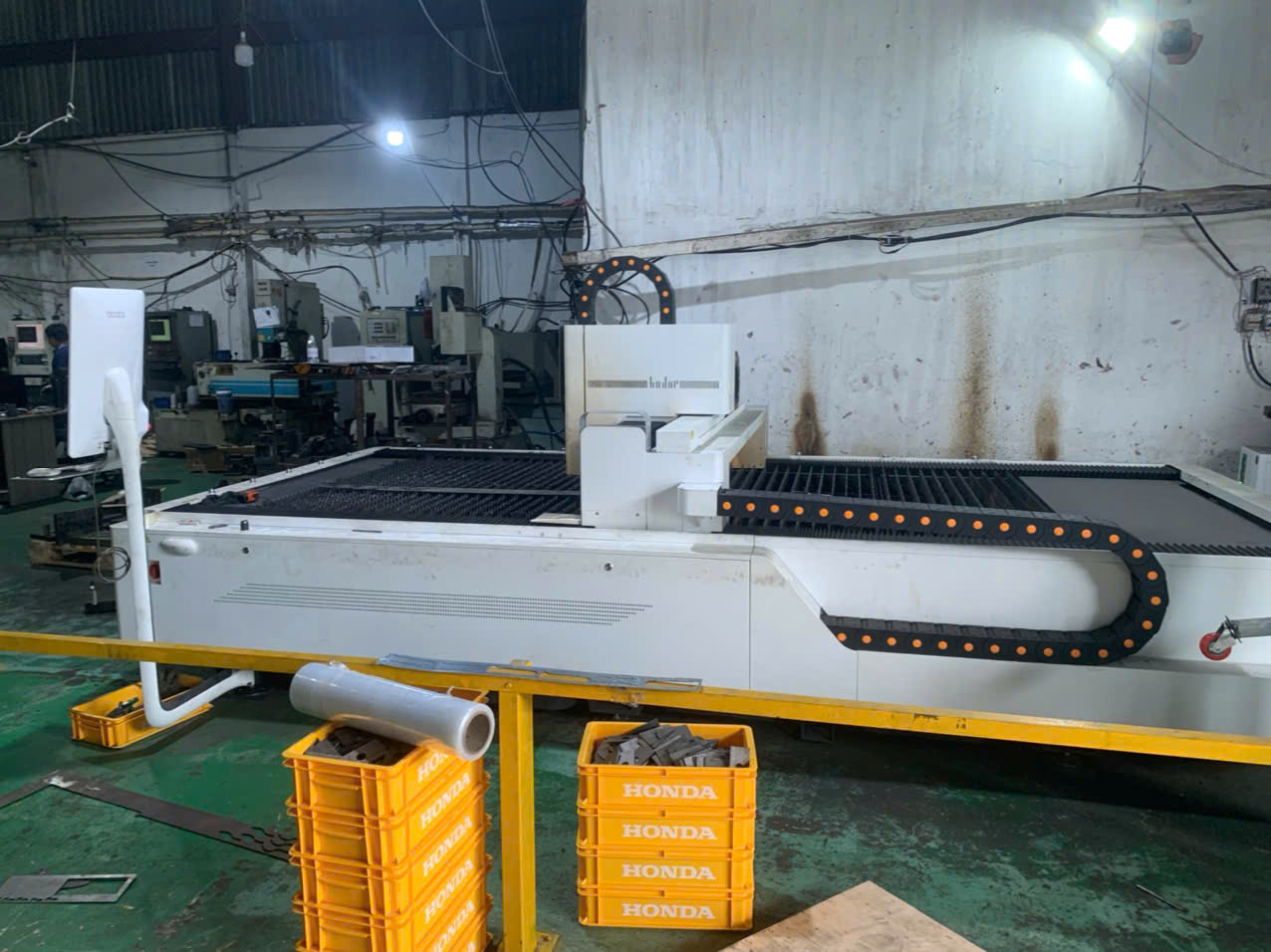
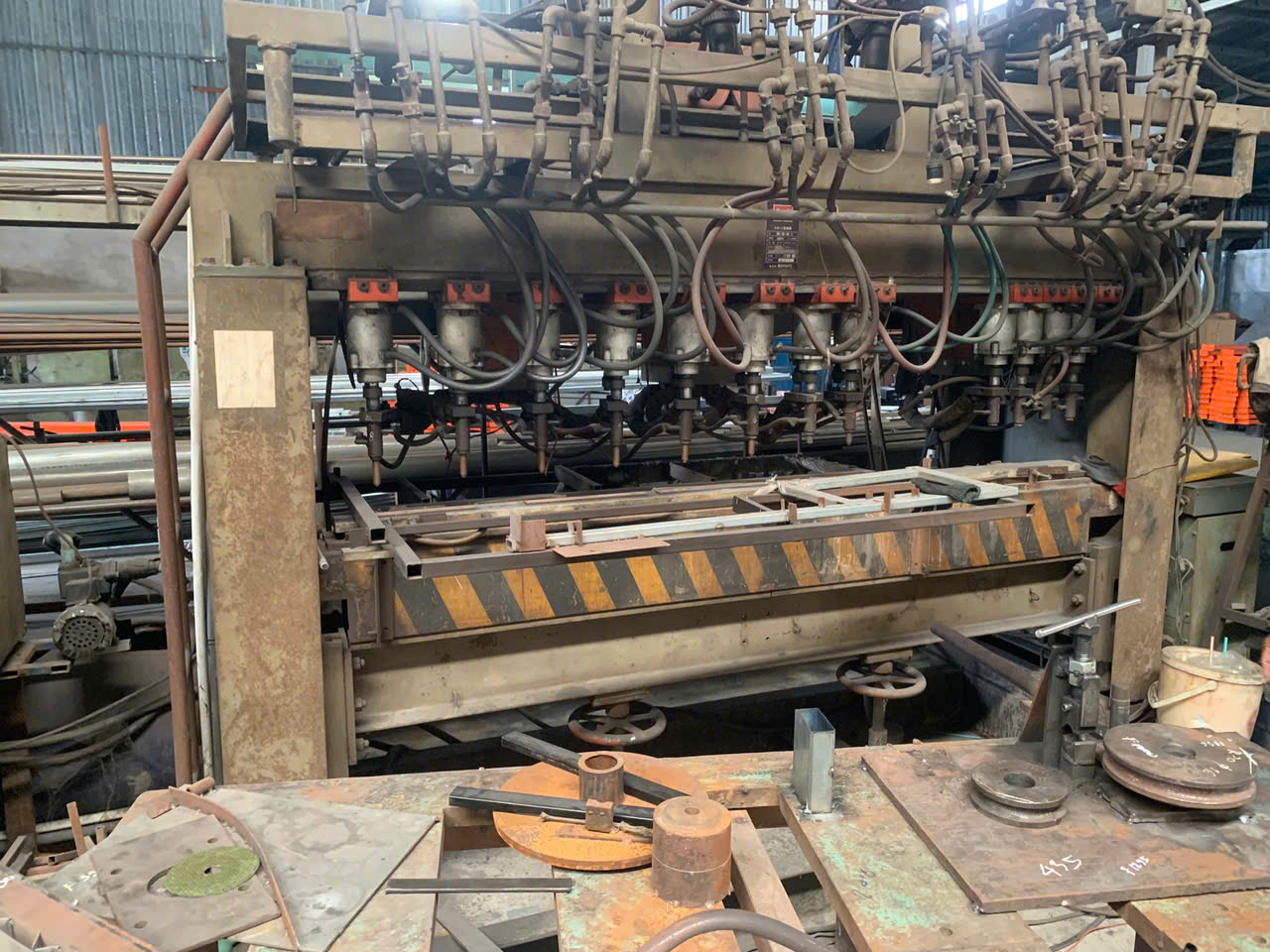
Every week on our production floor, we see how one wrong welding choice ruins an entire batch of thin gauge metal parts — costing buyers thousands in rework and delays.
The most common welding processes in sheet metal fabrication are MIG welding, TIG welding, resistance spot welding, and laser welding. Each process suits different material types, thicknesses, and production volumes. Selecting the right method prevents heat distortion, burn-through, and costly quality failures.
This article breaks down each welding process, compares their strengths, and gives you practical guidance for sourcing custom sheet metal parts that meet your engineering standards the first time.
Which welding process is most suitable for my custom sheet metal project?
A purchasing manager from the Midwest once sent us drawings for a stainless steel mounting bracket — only 1.2 mm thick — and asked for MIG welding 1 because it was "cheaper." We ran a quick test coupon and the part warped beyond tolerance within seconds.
The most suitable welding process depends on your material type, sheet thickness, joint design, and production volume. TIG welding excels for thin stainless steel and aluminum under 2 mm. MIG welding handles thicker steel efficiently. Spot welding dominates high-volume automotive panels and lap joints.
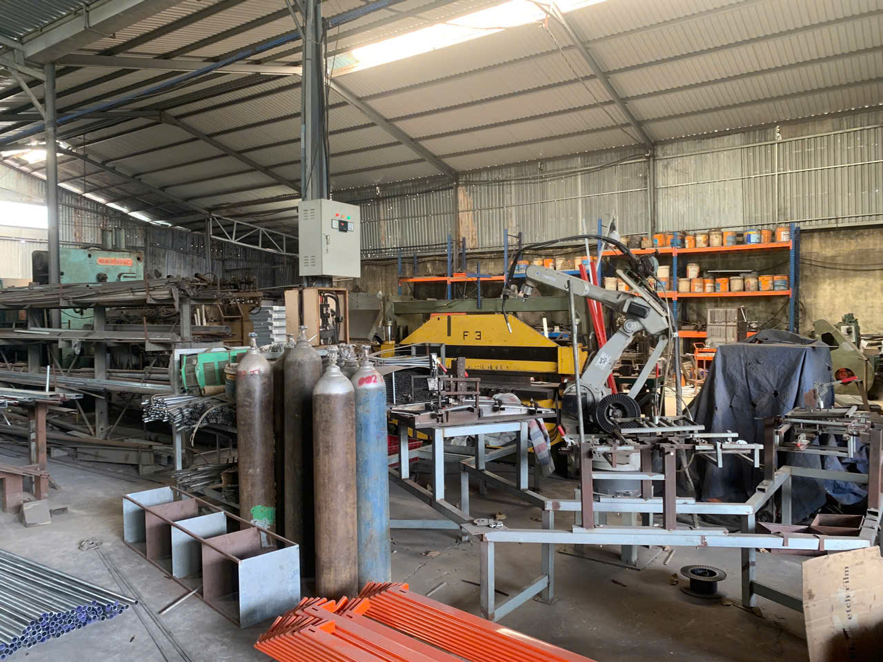
Choosing the right welding process is not just a technical decision Dye penetrant testing 2. It directly affects your unit cost, lead time, scrap rate, and final part quality. Let me walk you through the key processes and when each one makes sense tungsten electrode 3.
MIG Welding (GMAW)
MIG welding uses a continuously fed wire electrode and shielding gas 4 — typically an argon and CO₂ mix — to create the weld. It is fast, easy to learn, and works well for steel and aluminum in the 0.5–3 mm thickness range. On our Vietnam production line, we default to MIG for general fabrication brackets and enclosures where cosmetic appearance is secondary.
The key to MIG welding on thin gauge metal is using short-circuit transfer mode. This keeps the heat input low and reduces the risk of burn-through. Our welders typically run 30–90 amps for sheet metal work, with travel speeds of 30–100 cm/min.
TIG Welding (GTAW)
TIG welding 5 uses a non-consumable tungsten electrode and a separate filler metal rod. The welder controls the heat with a foot pedal. This makes it ideal for very thin materials — 0.5 to 2 mm — and for visible seams on stainless steel and aluminum welding applications.
TIG is slower. A typical TIG weld runs at 20–60 amps for sheet metal. But the result is a cleaner, more precise bead with minimal spatter. When our clients need polished or food-grade finishes, TIG is always the answer.
Spot Welding
Resistance spot welding 6 joins overlapping sheets by applying pressure and a high electrical current — typically 4–8 kA peak — at the contact point. No filler metal is needed. Each spot takes only 0.1–0.5 seconds. This makes it extremely fast for high-volume production of automotive panels and simple enclosures.
The limitation is joint design. Spot welding only works for lap joints. It cannot do butt joints, T-joints, or corner joints.
Quick Comparison of Core Welding Processes
| Feature | MIG Welding | TIG Welding | Spot Welding | Laser Welding 7 |
|---|---|---|---|---|
| Thickness Range | 0.5–3 mm | 0.5–2 mm | 0.8–3 mm | 0.5–2 mm |
| Typical Amperage | 30–90 A | 20–60 A | 4–8 kA (peak) | N/A |
| Speed | 30–100 cm/min | Slow | 0.1–0.5 sec/spot | Very fast |
| Filler Metal Required | Yes (wire) | Yes (rod) | No | Optional |
| Best For | General fabrication | Precision, thin parts | Mass production lap joints | Aerospace, electronics |
| Cosmetic Quality | Moderate | Excellent | Hidden joints | Excellent |
| Heat Distortion Risk | Moderate | Low (with skill) | Very low | Very low |
Laser and Plasma Arc Welding
Laser welding delivers a focused beam of energy to join thin sheet metals with minimal heat distortion. It is common in aerospace and precision electronics. The equipment cost is higher, but the results are outstanding for parts that cannot tolerate any warping. If you're evaluating different cutting and joining technologies, understanding the differences between laser and plasma cutting can also inform your process decisions.
Plasma arc welding is similar to TIG but uses a smaller, more concentrated plasma jet. It is faster than TIG and suits both thin and thick sheet metals. We see it most often in heavy equipment and aerospace applications.
Stitch and Tack Welding Techniques
Stitch welding — also called skip or intermittent welding — places small weld joints at regular intervals instead of running a continuous bead. This reduces heat input dramatically and prevents warping on thin parts.
Tack welding creates temporary small joints to hold parts in alignment before the final weld pass. Both techniques are essential heat management strategies that our welding teams use daily.
How do I ensure my supplier's welding quality meets my engineering standards?
The single biggest complaint we hear from U.S. purchasing managers is this: "My supplier missed critical drawing requirements, and now I have a container of parts that don't pass inspection." Welding quality issues account for a large share of these failures.
To ensure your supplier's welding quality meets your standards, require documented WPS (Welding Procedure Specifications), conduct first-article inspections with PPAP documentation, verify welder certifications, and perform destructive or non-destructive testing on sample parts before full production approval.
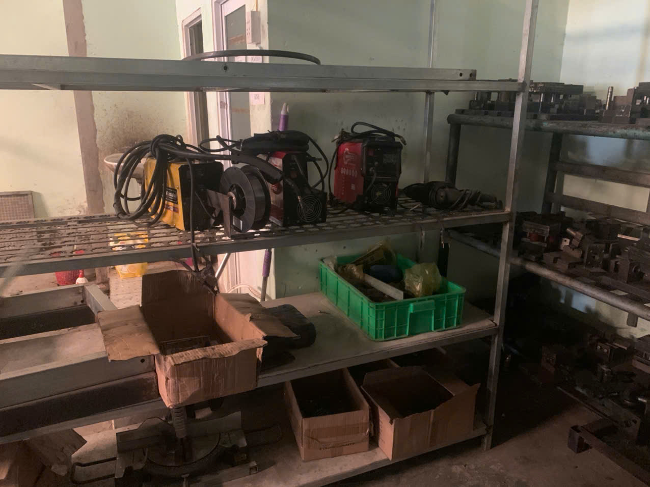
Quality in welding is not something you verify after the container arrives at your dock. It must be built into the process from the start. Here is how we approach it, and what you should demand from any supplier.
Define Welding Requirements Clearly on Drawings
Your engineering drawings must specify the weld type, weld symbol, acceptable penetration depth, surface finish requirements, and any post-weld treatments. Vague callouts like "weld all around" invite inconsistency. Be specific about filler metal type, joint design, and allowable heat distortion.
We review every drawing with our engineering team before quoting. If a weld callout is ambiguous, we ask for clarification rather than guessing. This step alone eliminates most first-article failures.
Implement a PPAP-Based Approval Process
A Production Part Approval Process 8 (PPAP) forces the supplier to prove they can produce the part consistently before mass production begins. For welded sheet metal parts, PPAP should include:
| PPAP Element | What It Covers for Welded Parts |
|---|---|
| Process Flow Diagram | Shows each step from cutting to welding to finishing |
| Control Plan | Defines inspection points, frequencies, and methods for weld quality |
| First Article Inspection Report | Dimensional and visual verification of initial welded samples |
| WPS (Welding Procedure Specification 9) | Documents exact parameters: process, amperage, shielding gas, speed |
| Welder Qualification Records | Proof that specific operators are certified for the required process |
| MSA (Measurement System Analysis) | Validates gauges and fixtures used to inspect weld quality |
Our team in China and Vietnam manages this entire PPAP flow. We do not ship production parts until the client signs off on first-article results.
Non-Destructive and Destructive Testing
For critical welded joints, visual inspection alone is not enough. Common testing methods include:
- Visual inspection (VT): Check for surface cracks, porosity, undercut, and bead consistency.
- Dye penetrant testing (PT): Reveals surface-breaking defects invisible to the naked eye.
- Destructive testing: Pull tests, bend tests, or cross-section macro analysis on sample coupons to verify penetration and fusion.
The key is to define which tests apply in your quality plan before production starts. Do not leave it to the supplier to decide.
Ongoing Process Control
First-article approval is not the finish line. Ongoing process control — including in-process inspections, final inspections, and periodic re-qualification — keeps quality stable across production runs. We assign a dedicated quality engineer to each welding project to monitor parameters and catch drift before it becomes a defect.
Should I prioritize TIG or MIG welding for my high-precision metal components?
Last quarter, a client needed decorative stainless steel panels for medical equipment housings. The panels were 1.0 mm thick. The previous supplier had used MIG welding and every single panel showed visible distortion and rough bead marks. The client was ready to switch suppliers — and switch welding processes.
For high-precision metal components, prioritize TIG welding when working with thin stainless steel or aluminum under 2 mm, or when cosmetic weld appearance matters. Choose MIG welding when speed and cost efficiency outweigh aesthetic requirements, typically for steel parts above 1.5 mm thick.
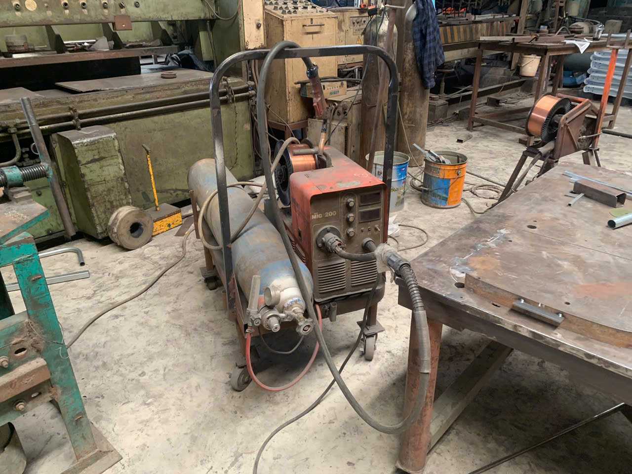
The TIG versus MIG decision is one of the most frequent trade-offs we help clients navigate. Neither process is universally better. The right choice depends on your specific part requirements.
Where TIG Welding Wins
TIG welding gives the welder direct control over heat input through a foot pedal and separate filler metal feed. This is critical for thin gauge metal where even a few extra amps cause burn-through. On our production floor, our TIG welders run pulse mode at 20–60 amps for parts under 2 mm. Pulse TIG alternates between high and low current, allowing the weld pool to cool between pulses. This dramatically reduces heat distortion.
TIG also produces the cleanest bead. For visible seams on stainless steel enclosures, food-grade equipment, or architectural metalwork, TIG is the only practical choice. The weld bead can be ground and polished to near-invisible.
Where MIG Welding Wins
MIG welding is 2–4 times faster than TIG for equivalent joint lengths. The continuously fed wire electrode means less stopping and starting. For structural brackets, internal frames, and parts that will be painted or hidden, MIG delivers excellent joint strength at a lower labor cost.
Cold Metal Transfer (CMT), a variation of MIG welding, is gaining traction for ultra-thin applications. CMT uses a mechanically retracting wire tip to reduce heat input to near-zero spatter levels. We have started using CMT on aluminum welding projects where heat distortion was previously unacceptable with standard MIG.
Head-to-Head Comparison
| Decision Factor | TIG Welding | MIG Welding |
|---|---|---|
| Ideal Thickness | 0.5–2 mm | 0.5–3 mm |
| Welding Speed | Slow (manual filler feed) | Fast (continuous wire feed) |
| Heat Control | Excellent (foot pedal + pulse) | Good (short-circuit mode) |
| Cosmetic Quality | Superior — clean, smooth bead | Moderate — spatter possible |
| Operator Skill Required | High | Moderate |
| Cost per Weld | Higher (slower) | Lower (faster) |
| Best Materials | Stainless steel, aluminum, titanium | Carbon steel, aluminum, stainless |
| Shielding Gas | Pure argon | Argon/CO₂ mix |
| Automation Potential | Moderate | High |
Pulse Modes: Bridging the Gap
Both pulse MIG and pulse TIG are trending in sheet metal fabrication. Pulse modes alternate the current between a peak and a background level. This controls the heat input per unit time and enables welding on thinner materials than traditional continuous modes allow.
For parts in the 0.5–1.5 mm range, pulse TIG remains the gold standard. For parts in the 1.5–3 mm range where speed matters, pulse MIG offers a strong balance of quality and productivity. We recommend discussing pulse mode options with your supplier early in the quoting stage.
How can I avoid common welding errors when sourcing custom parts from overseas?
During a supplier audit at a factory in Southeast Asia, I watched a welder join two 1.0 mm stainless steel panels using continuous MIG at 85 amps with no backing. The result was predictable: a row of burn-through holes along the entire seam. The factory had no WPS, no quality control checkpoints, and no awareness that anything was wrong.
To avoid common welding errors when sourcing overseas, specify welding processes and parameters on your drawings, require PPAP approval before production, audit your supplier's welding capabilities in person or through a third party, and insist on documented in-process and final inspection protocols.
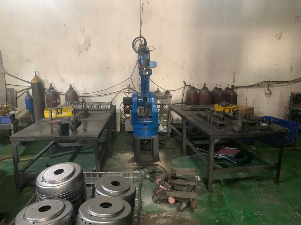
Sourcing welded sheet metal parts from Asia introduces risks that domestic buyers do not always anticipate. Language barriers, different quality cultures, and distance make it harder to catch problems early. Here are the most common errors and how to prevent them.
Error 1: Wrong Process Selection
Many overseas suppliers default to the welding process their workers know best — not the process your part requires. If your drawing does not specify the welding method, the supplier will choose based on convenience. Always call out the required process (MIG, TIG, spot welding, laser welding) directly on the drawing or in the purchase order.
Error 2: Excessive Heat Input
Heat distortion and burn-through are the most common defects on thin sheet metal parts sourced from Asia. Suppliers often run higher amperage than necessary because it is faster. The fix is to specify amperage ranges and require short-circuit or pulse transfer modes for thin materials.
Heat management best practices include:
- Use stitch or skip welding instead of continuous beads.
- Alternate weld locations to distribute heat evenly across the part.
- Use smaller diameter filler metal wire — 0.8 mm instead of 1.0 mm — to reduce heat input.
- Allow cooling time between weld passes.
- Use copper backing bars or heat sinks for very thin panels.
Error 3: Poor Fit-Up and Fixturing
If the parts do not fit tightly before welding, the welder must fill gaps with extra filler metal and more heat. This causes distortion and weak joints. Proper fixturing and tack welding before the final weld pass are essential. Upstream processes like bending in sheet metal fabrication also affect fit-up accuracy, so dimensional control must start well before the welding stage. We require our suppliers to submit photos of fixturing setups during the PPAP phase.
Error 4: No In-Process Inspection
Many suppliers only inspect at the end of the line. By then, a systemic welding error has already affected the entire batch. We place inspection checkpoints after every critical welding operation — not just at final packaging.
Error 5: Ignoring Shielding Gas Quality
Contaminated or incorrect shielding gas causes porosity, oxidation, and brittle welds. For TIG welding on stainless steel, pure argon is mandatory. For MIG welding on carbon steel, an argon/CO₂ blend (typically 75/25) is standard. Verify that your supplier uses the correct gas and replaces cylinders before they run too low — the last bit of gas in a cylinder often contains moisture.
Supplier Qualification Checklist
Before awarding a welding-intensive project to an overseas supplier, we recommend verifying the following:
- Does the supplier have certified welders for the required process?
- Can they provide a Welding Procedure Specification for your specific part?
- Do they have proper fixturing and jig capabilities?
- Is there an in-process inspection plan with documented checkpoints?
- Can they perform or subcontract non-destructive testing if required?
- Do they have traceability for filler metal and shielding gas lots?
Our team at DEWIN handles this entire qualification process for clients sourcing from Vietnam, China, Taiwan, and India. We conduct on-site audits, manage PPAP submissions, and run final inspections before shipment — so the parts that arrive at your dock meet your engineering standards the first time.
Conclusion
Welding processes in sheet metal fabrication each serve distinct purposes. Match the process to your material, thickness, and quality requirements — and invest in supplier qualification to get it right the first time.
Frequently Asked Questions
Which welding process is most suitable for my custom sheet metal project?
A purchasing manager from the Midwest once sent us drawings for a stainless steel mounting bracket — only 1.2 mm thick — and asked for MIG welding 1 because it was "cheaper." We ran a quick test coupon and the part warped beyond tolerance within seconds.
How do I ensure my supplier's welding quality meets my engineering standards?
The single biggest complaint we hear from U.S. purchasing managers is this: "My supplier missed critical drawing requirements, and now I have a container of parts that don't pass inspection." Welding quality issues account for a large share of these failures.
Should I prioritize TIG or MIG welding for my high-precision metal components?
Last quarter, a client needed decorative stainless steel panels for medical equipment housings. The panels were 1.0 mm thick. The previous supplier had used MIG welding and every single panel showed visible distortion and rough bead marks. The client was ready to switch suppliers — and switch welding processes.
Footnotes
1. Explains the MIG welding process, techniques, advantages, and applications. ↩︎
2. Explains dye penetrant testing as an NDT method for detecting surface-breaking defects. ↩︎
3. Details the types, selection, and proper use of tungsten electrodes in TIG welding. ↩︎
4. Provides an overview of common shielding gases used in welding and their functions. ↩︎
5. Replaced HTTP 404 link with an authoritative source on TIG welding (GTAW) from the American Welding Society (AWS). ↩︎
6. Details the principles, process, and applications of resistance spot welding. ↩︎
7. Explains what laser welding is, how it works, and its advantages in manufacturing. ↩︎
8. Defines PPAP and its critical role in ensuring consistent part quality in manufacturing. ↩︎
9. Replaced HTTP 403 link with an authoritative source on Welding Procedure Specifications (WPS) from the American Welding Society (AWS). ↩︎
10. Authoritative source for non-destructive testing, its methods, and professional standards. ↩︎