Every week, our engineering team in Vietnam and China reviews drawings that push the limits of what flat metal can become — and the answer surprises even seasoned buyers.
Custom sheet metal fabrication can achieve an extraordinary range of complex shapes and structures — from standard brackets and enclosures to intricate 3D geometries like curved facades, precision aerospace components, and decorative filigree — by leveraging laser cutting, CNC bending, deep drawing, hydroforming, welding services, and custom tooling.
This article walks you through the specific shapes possible, the technologies that make them happen, and how to work with your supplier to get it right the first time. Whether you source from Asia or manufacture domestically, these fundamentals apply.
How can I determine if my complex sheet metal design is feasible for manufacturing?
A U.S. client once sent us a bracket drawing with six bends, two counter-bores, and a tolerance call-out of ±0.1 mm — then asked, "Can you even make this?" The answer started with a proper design for manufacturability review 1.
You can determine feasibility by conducting a design for manufacturability (DFM) review that evaluates material selection, bend radii, grain direction, minimum feature sizes, and tolerance stack-ups against your fabricator's actual equipment capabilities and process limits.
Start With a DFM Checklist
Before any metal gets cut, we sit down with the client's engineering files. The first question is always: does the geometry match the process? A shape that looks simple on screen may require custom tooling or a secondary operation that doubles the cost. Here is a basic checklist we use internally:
| DFM Factor | What to Check | Red Flag |
|---|---|---|
| Bend radius | Must be ≥ material thickness | Radius smaller than thickness cracks the metal |
| Minimum feature size | Holes, slots, tabs ≥ 1 × 1 mm for laser cutting 2 | Features below 1 mm risk distortion |
| Grain direction | Bend lines should cross the grain, not run parallel | Parallel bends cause cracking |
| Tolerance stack-up 3 | Cumulative tolerances across multiple bends | Stack-up exceeds ±0.13 mm per feature |
| Material selection | Formability rating of the chosen alloy | High-strength steel with tight bends |
| Flat pattern feasibility | Can the 3D shape unfold into a single flat blank? | Overlapping geometry in flat state |
Understand Your Process Options
Not every complex shape requires the same process. Some parts need only laser cutting and a single bend. Others demand deep drawing 4, hydroforming, or even CNC milling from billet for extreme curves. Knowing which process fits your geometry saves time and money.
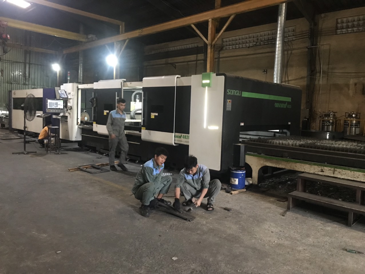
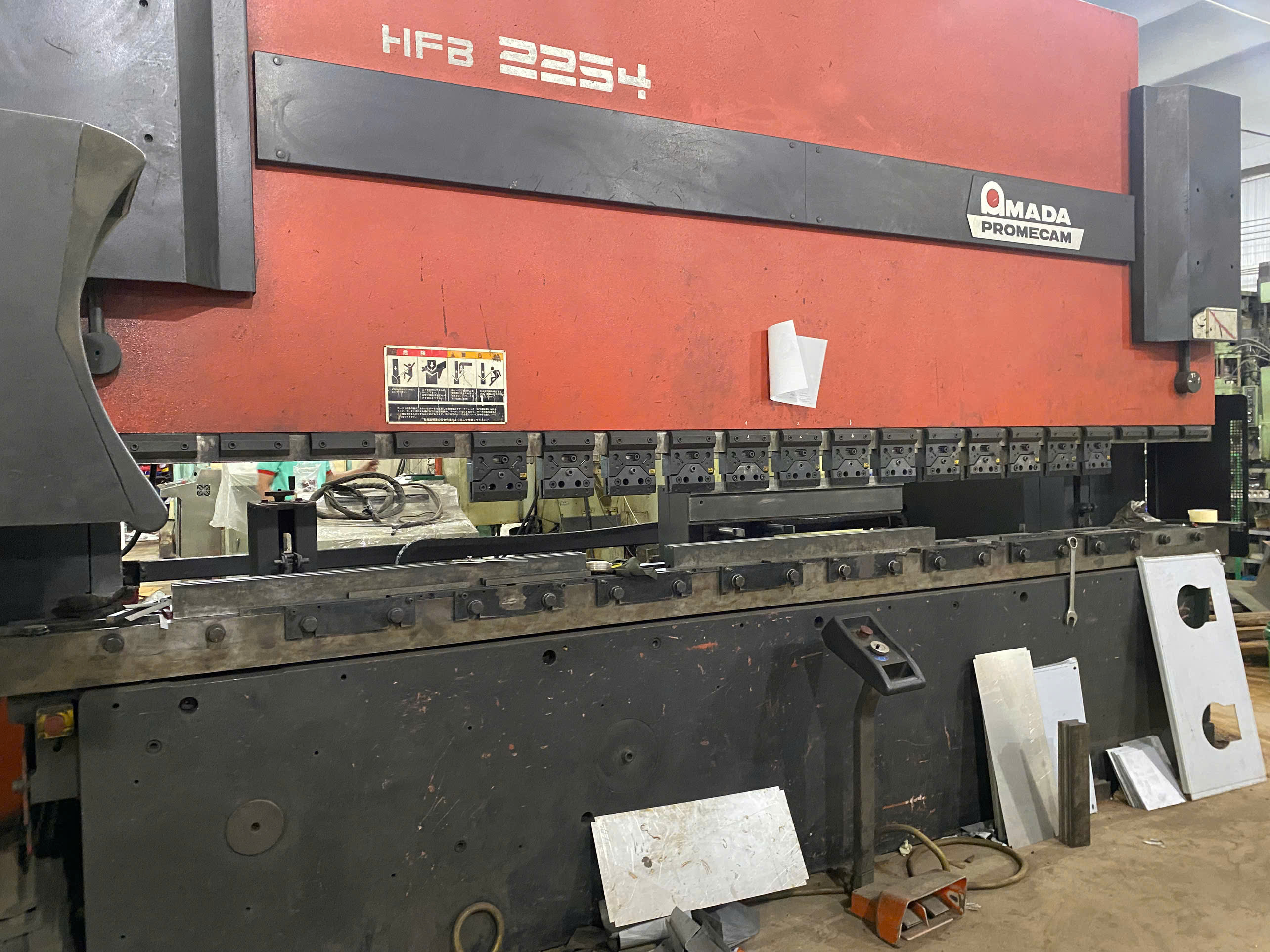
When our team in China audits a supplier for a new project, we verify which machines sit on the floor. A shop with a 200-ton press brake handles most bracket and enclosure work. But a part with compound curves may need a hydraulic press with custom dies. We map the design features to the equipment before quoting.
Grain Direction Matters More Than You Think
Metal has a grain, just like wood. If you bend against the grain, the part holds shape. If you bend along it, cracks appear. For complex parts with bends in multiple directions, we orient the blank so the most critical bend crosses the grain. This single step prevents most first-article failures.
For intricate designs with tight curves in multiple planes, freeforming or drop hammer techniques may be needed. These require a high skill level from the operator. We flag these situations early so clients can adjust geometry or budget accordingly.
What specific structural features can I incorporate into my custom metal parts?
Last quarter, a purchasing manager in the Midwest asked us to consolidate five separate stamped pieces into one fabricated assembly. The conversation quickly turned to which features — flanges, louvers, embosses, threaded inserts — could be combined into a single part.
You can incorporate a wide variety of structural features into custom metal parts, including precision bends, flanges, tabs, embossed ribs, countersunk holes, threaded hardware inserts, welded joints, rolled edges, and complex cutouts — all achievable through laser cutting, CNC bending, the stamping process, and welding services.
Standard Profiles and Beyond
The foundation of sheet metal fabrication starts with well-known structural shapes. Beams, angles, channels, and hollow structural shapes (HSS) come in square, rectangular, and elliptical profiles. These are often starting stock that fabricators further cut, drill, and weld into custom assemblies.
But custom fabrication goes far beyond catalog profiles. Here is a breakdown of structural features we commonly produce:
| Feature Category | Specific Features | Typical Process |
|---|---|---|
| Bends and folds | L-bends, U-channels, V-bends, Z-bends, hemmed edges | CNC press brake |
| Cutouts and patterns | Complex perforations, slots, decorative patterns | Laser cutting, waterjet |
| Surface features | Embossed ribs, dimples, louvers, lance-and-form | Stamping process 5, press tooling |
| Joining features | Weld tabs, spot weld pads, rivet holes | Welding services, mechanical fastening |
| Hardware integration | PEM nuts, studs, standoffs, captive fasteners | Hardware insertion press |
| 3D forms | Enclosures, housings, deep-drawn cups, rolled cylinders | Deep drawing, rolling, CNC bending |
Cutting Technologies That Enable Intricate 2D Shapes
Laser cutting is the premier method for creating clean, precise cuts. Modern fiber lasers achieve dimensional accuracy of ±0.13 mm and minimum feature sizes of 1 × 1 mm. They cut intricate designs — decorative filigree, complex perforations, tight-radius contours — without breakout tabs. This means perfect edges straight off the machine.
Plasma cutting handles thicker materials and complex curves at lower cost but produces a cruder edge. Waterjet cutting works well for heat-sensitive materials, since it introduces no thermal distortion.
From Flat to 3D: Forming and Joining
Once the flat blank is cut, the real transformation begins. Press brakes use a punch and die to bend metal into precise angles. Air bending uses a V-shaped die and controls angle by punch depth. Bottoming forces the metal flat against the die for tighter tolerances. Rolling creates cylinders and curves. Folding produces long, straight bends in large panels.
For shapes that standard dies cannot form, we work with suppliers who fabricate custom tooling. This is common for parts with non-standard radii or compound angles.
Welding then joins individual pieces into complete assemblies. A flat sheet becomes an enclosure. Two brackets become a mounting frame. Hardware insertion adds threaded standoffs and captive nuts. The result is a fully functional component ready for the end application.
Optimized and Hybrid Structures
Modern fabrication also supports lattice structures and topology-optimized geometries that reduce weight while maintaining strength. In aerospace and automotive applications, this matters enormously. Hybrid multi-material structures — joining aluminum to stainless steel, or integrating plastic inserts into metal frames — expand what a single assembly can do.
We have also seen growing demand for parts with embedded sensor mounts and internal wiring channels, especially from clients in the consumer electronics space.
How do I ensure my supplier can handle the intricate bends and shapes I require?
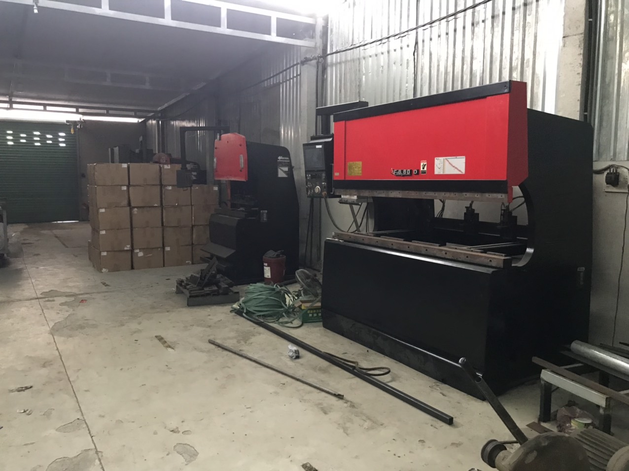
During a supplier audit at a factory outside Ho Chi Minh City, I watched an operator set up a 160-ton CNC press brake with a custom-ground punch. The part had four bends within 30 mm of each other. Without the right tooling and programming, those bends would have collided. That visit told me more about capability than any email exchange ever could.
You can ensure your supplier handles intricate bends and shapes by auditing their equipment list, verifying CNC press brake tonnage and tooling inventory, reviewing first-article inspection reports, requesting sample parts, and confirming they follow documented process control procedures like PPAP.
Evaluate Equipment and Tooling
The first step is understanding what sits on the shop floor. A supplier with only manual brakes and basic V-dies cannot consistently produce parts that require tight tolerances or compound bends. Here is what to look for:
| Equipment / Capability | Why It Matters | Minimum Expectation |
|---|---|---|
| CNC press brake | Programmable back-gauge ensures repeatable bend positions | At least one CNC brake with ≥ 100-ton capacity |
| Tooling library | Standard and custom punches/dies for varied radii and angles | Segmented tooling, gooseneck punches, acute dies |
| Laser cutter | Precision flat blanks feed directly into forming | Fiber laser with ±0.13 mm accuracy |
| Rolling equipment | Cylinders, cones, and curved panels | 3-roll or 4-roll plate roller |
| Welding stations | MIG, TIG, spot welding for assembly | Certified welders, documented WPS |
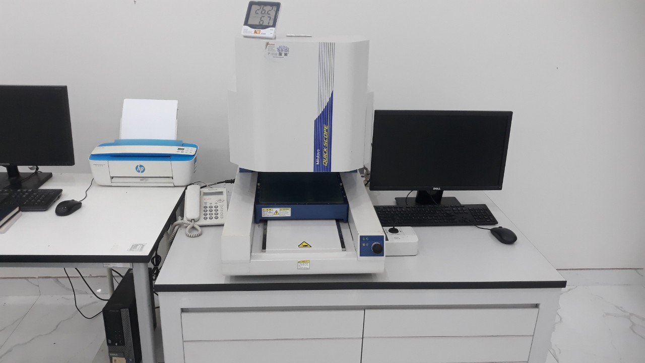
| Inspection tools | CMM, calipers, angle gauges, go/no-go fixtures | Calibrated instruments with traceability |
Request First-Article Samples
Never skip the first-article inspection. We build PPAP (Production Part Approval Process) 6 into every new project. The supplier produces a small batch, measures every critical dimension, and submits a report. We compare the results against the drawing. If something is off, we correct the process before full production begins.
This step is especially critical for parts with intricate designs — multi-bend brackets, deep-drawn housings, or welded assemblies with tight fit-up requirements. A first-article run catches problems that even a thorough DFM review might miss.
Verify Process Control Documentation
A capable supplier documents everything: machine settings, tool selections, inspection frequencies, and corrective actions. When we manage projects for U.S. clients sourcing from Vietnam or other Asian countries outside China, we insist on control plans and in-process inspection checklists.
Why does this matter? Because precision engineering is not just about having the right machine. It is about running the machine the same way every time. Without documented procedures, quality drifts. Bends shift by half a degree. Holes migrate by a tenth of a millimeter. Over a production run of thousands of parts, these small errors become big problems.
Consider Online Fabrication Services for Prototyping
The rise of online custom sheet metal services has changed how buyers prototype complex parts. You can upload a STEP or DXF file and get an instant quote with delivery in days. This is useful for testing a design before committing to a full production supplier. However, for volume production with tight tolerances, a vetted manufacturing partner with process control will outperform an online portal every time.
How can I maintain high quality and precision across my most complex sheet metal assemblies?
One lesson we learned early in our supply chain work: the most common reason for rejected sheet metal assemblies is not a bad machine or bad material. It is a breakdown in communication between the buyer's engineering team and the supplier's shop floor.
You maintain high quality and precision across complex sheet metal assemblies by implementing rigorous process controls — including PPAP, in-process dimensional checks, final inspection with CMM verification, clear engineering drawings with GD&T, and consistent communication between your engineering team and the supplier.
Define Quality at the Drawing Level
Quality starts before production. Every critical dimension needs a tolerance. Every surface finish needs a call-out. GD&T (Geometric Dimensioning and Tolerancing) 7 removes ambiguity. When we review drawings for clients, we look for missing datum references, unclear weld symbols, and tolerance conflicts that would confuse the shop floor.
A common mistake: specifying tight tolerances everywhere. This drives cost up without improving function. Apply tight tolerances only where fit and function demand them. Let non-critical dimensions float within standard fabrication tolerances.
Build Quality Into the Process
Quality is not something you inspect into a part. You build it in. Here is how we structure process control for complex assemblies:
-
Pre-production review. Engineering, quality, and production teams walk through the drawing together. They identify critical features, select tooling, and set inspection points.
-
First-article inspection. The first pieces off the line get full dimensional checks. Results feed back into the setup.
-
In-process checks. Operators measure key dimensions at defined intervals — every 20th part, every setup change, every shift start.
-
Final inspection. A quality inspector verifies the completed assembly against the drawing before packing. For critical parts, CMM (Coordinate Measuring Machine) 8 verification ensures precision engineering standards are met.
-
Shipping inspection. Our team performs a final check before the parts leave the facility, verifying count, packaging, and labeling.
Managing Tolerance Stack-Up in Multi-Part Assemblies
When an assembly includes multiple fabricated pieces joined by welding or hardware, tolerances stack. A bracket with ±0.2 mm tolerance bolts to a panel with ±0.2 mm tolerance. The assembly now has ±0.4 mm potential misalignment. For complex assemblies, we use fixture-welding jigs and assembly fixtures to control cumulative error.
This is where many suppliers fall short. They can make individual parts to spec but lose control during assembly. Our approach — managing the supply chain from raw material through final assembly and door-to-door logistics — closes that gap.
Cost vs. Complexity: Know the Trade-Offs
For extremely complex shapes with tight compound curves, sheet metal fabrication may not be the most cost-effective route. CNC milling from billet produces virtually any geometry but wastes material and costs significantly more. Hydroforming 9 shapes metal with fluid pressure and works well for automotive panels but requires expensive tooling. The stamping process excels at high volumes but demands die investment.
The right answer depends on volume, geometry, and budget. We help clients evaluate these trade-offs so they choose the process that delivers the required precision without overspending. Understanding the difference between precision and standard sheet metal fabrication is a key part of making that decision.
Conclusion
Custom sheet metal fabrication achieves remarkably complex shapes — from simple brackets to intricate 3D assemblies — when you pair the right processes, equipment, and quality controls with a supplier who communicates clearly and delivers consistently. To explore the full range of processes available, review the main types and classifications of sheet metal fabrication.
Frequently Asked Questions
How can I determine if my complex sheet metal design is feasible for manufacturing?
A U.S. client once sent us a bracket drawing with six bends, two counter-bores, and a tolerance call-out of ±0.1 mm — then asked, "Can you even make this?" The answer started with a proper design for manufacturability review 1 .
What specific structural features can I incorporate into my custom metal parts?
Last quarter, a purchasing manager in the Midwest asked us to consolidate five separate stamped pieces into one fabricated assembly. The conversation quickly turned to which features — flanges, louvers, embosses, threaded inserts — could be combined into a single part.
How do I ensure my supplier can handle the intricate bends and shapes I require?
During a supplier audit at a factory outside Ho Chi Minh City, I watched an operator set up a 160-ton CNC press brake with a custom-ground punch. The part had four bends within 30 mm of each other. Without the right tooling and programming, those bends would have collided. That visit told me more about capability than any email exchange ever could.
Footnotes
1. Replaced HTTP 403 with a Wikipedia article on Design for Manufacturability (DFM) for an authoritative overview. ↩︎
2. Provides details on the principles and applications of laser cutting technology. ↩︎
3. Replaced HTTP 404 with a Wikipedia article on tolerance analysis, which covers tolerance stack-up. ↩︎
4. Replaced HTTP 404 with a Wikipedia article providing a comprehensive explanation of deep drawing. ↩︎
5. Replaced HTTP 403 with a Wikipedia article on metal stamping for a general overview of the process. ↩︎
6. Defines the Production Part Approval Process for ensuring part quality. ↩︎
7. Replaced HTTP 403 with a Wikipedia article offering a detailed explanation of GD&T. ↩︎
8. Replaced HTTP 403 with a Wikipedia article providing an overview of Coordinate Measuring Machines. ↩︎
9. Replaced HTTP 404 with a Wikipedia article detailing the hydroforming process. ↩︎