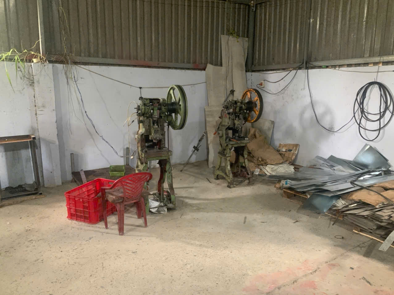

A recent project taught us a costly lesson: a stamped bracket with a tight bend fit perfectly in CAD but refused to seat into its cast aluminum housing on the assembly line.
Design requirements ensuring fit between stamping parts and molded or cast parts include aligned tolerance stack-up analysis, shared datum feature selection, clearance allowances for burrs and shrinkage, draft angle requirements on cast surfaces, and mating surface specifications that account for material springback and thermal expansion coefficients across dissimilar material assemblies.
Getting these mixed-process assemblies right the first time is not luck Root Sum Square 1. It is a discipline that starts on the drawing board and carries through every stage of production. This article breaks down the critical design requirements we apply daily when coordinating stamped, molded, and cast components for our U.S. and European clients.
What tolerance stack-up considerations should I address between stamped and molded components?
One lesson we learned early in our co-development work is that tolerance problems rarely show up in a single part—they compound at every interface.
You should address tolerance stack-up by performing a statistical RSS analysis across all mating features, harmonizing the tighter stamping tolerances with the wider molding or casting tolerances, and establishing a unified datum scheme so both parts reference the same physical points during inspection and assembly.

Why Tolerance Stack-Up Matters More in Mixed-Process Assemblies
When a stamped bracket meets a molded housing, you are combining two very different tolerance worlds. Stamping holds tight dimensions on flat features. But bends carry an angular tolerance of ±1 degree. Molded or cast parts, on the other hand, have wider dimensional variation due to shrinkage and warping. If you simply add worst-case tolerances together, the total variation may exceed the available clearance at the assembly interface.
That is why a tolerance stack-up analysis 2 using the Root Sum Square (RSS) method is more practical than a worst-case approach. RSS assumes that not all dimensions will land at their extreme limits at the same time. This gives you a realistic picture of actual fit variation without over-engineering every feature.
Typical Tolerance Ranges by Process
| Parameter | Stamping (Sheet Metal) | Injection Molding | Die Casting |
|---|---|---|---|
| Linear Tolerance | ±0.05 mm to ±0.15 mm | ±0.1 mm to ±0.3 mm | ±0.1 mm to ±0.5 mm |
| Angular Tolerance | ±1 degree on bends | ±0.5 degree (mold dependent) | ±0.5 degree (draft dependent) |
| Flatness | 0.003 in/in achievable | 0.005 in/in typical | 0.005–0.010 in/in typical |
| Surface Finish | Ra 0.8–3.2 µm | Ra 0.1–1.6 µm (mold surface) | Ra 1.6–6.3 µm |
Establishing a Unified Datum Strategy
In our PPAP documentation 3, we insist that both the stamped part and the molded part share the same primary datum references. If the stamped bracket is located by two holes and one edge, the mating cast housing must reference the same two pins and one surface. This eliminates measurement drift between suppliers. It also makes incoming inspection straightforward—both parts can be checked on the same fixture.
Geometric Dimensioning and Tolerancing (GD&T) is the language that makes this possible. We call out position tolerances 4 on mating holes relative to shared datums, not just basic linear dimensions. This way, even if one supplier measures from a different corner of the part, the functional fit is still controlled.
The Real Cost of Ignoring Stack-Up
When our team in Vietnam audited a supplier last year, we found a stamped clip with a ±0.1 mm hole position tolerance mating with a cast boss that had ±0.3 mm position tolerance. The combined worst-case variation was 0.8 mm—but the design clearance was only 0.5 mm. Parts jammed during assembly. A quick RSS calculation showed the statistical variation was about 0.63 mm, still too tight. The fix was simple: open the clearance hole in the stamped part by 0.4 mm. No tooling change was needed on the casting side. This kind of proactive analysis saves weeks of rework.
How can I design mating features to prevent misalignment between stamping and casting parts?
A U.S. client once asked us to source a stamped steel insert that press-fits into a die-cast zinc housing—and the first sample batch had a 15% rejection rate due to misalignment during manual assembly.
You can prevent misalignment by incorporating self-locating features such as lead-in chamfers, poka-yoke geometries, and compliant spring tabs on the stamped part, while ensuring the cast or molded part includes adequate draft angles and locating bosses that guide the stamped component into position during assembly.
Self-Locating Features Save Assembly Time
The simplest way to prevent misalignment is to design parts that can only go together one way. This is the poka-yoke principle. On the stamped part, add an asymmetric tab, a notch, or a locating hole pattern that matches a unique feature on the cast housing. This eliminates the possibility of inserting the stamped part backwards or rotated 180 degrees.
Lead-in chamfers are equally important. A 15-degree to 30-degree chamfer on the entry edge of a cast pocket 5 guides the stamped part into the correct position. Without this chamfer, operators must align the parts by hand, which introduces variability and slows the line.
Clearance for Burrs and Draft Angles
Stamping produces burrs. On a 1.5 mm thick steel bracket, burrs can extend up to 0.15 mm (10% of thickness). If the mating slot in the cast part has zero clearance, these burrs will prevent full seating. Our standard practice is to add clearance equal to the maximum burr height plus 0.1 mm on each side of the mating interface.
Cast and molded parts also require draft angles 6 for mold ejection. A vertical wall on a cast housing might have 1 to 3 degrees of draft. If a stamped part mates flat against this wall, the draft creates a gap at one end. You must account for this taper in your interference and clearance fits calculations.
| Mating Feature | Design Recommendation | Why It Matters |
|---|---|---|
| Lead-In Chamfer | 15°–30° on cast pocket entry | Guides stamped part into position |
| Burr Clearance | Burr height + 0.1 mm per side | Prevents binding during insertion |
| Poka-Yoke Tab | Asymmetric notch or key feature | Eliminates wrong-orientation assembly |
| Locating Boss/Pin | Diameter tolerance ±0.05 mm | Centers stamped hole on cast feature |
| Compliant Tab | Spring-loaded stamped finger | Absorbs casting dimensional variation |
| Draft Compensation | Match stamped surface to draft angle | Prevents wedge gaps at interface |
Compliant Features for Absorbing Variation
When the cast or molded part has inherent dimensional scatter, a rigid stamped part will either fit perfectly or not at all. A better approach is to build compliance into the stamped design. A spring tab or a flexural finger on the stamped bracket can absorb 0.2–0.5 mm of variation in the cast part without rattling or losing clamp force. We have used this approach successfully on insert molding design projects where the stamped metal insert must seat inside a plastic housing that varies slightly from shot to shot.
Stiffening Against Oil-Canning
Large flat areas on stamped parts tend to buckle under light pressure—a defect called oil-canning. If this flat area mates against a cast surface, the buckle creates a gap and ruins the fit. Adding small beads or embossed ribs to the stamped surface prevents this distortion and keeps the mating surface specifications consistent.
Which material shrinkage and thermal expansion factors do I need to account for in mixed-process assemblies?
During a supplier audit in China, our quality team discovered that a plastic-overmolded stamped terminal was cracking after thermal cycling—not because of a bad mold, but because nobody had calculated the CTE mismatch between the steel insert and the nylon housing.
You need to account for post-molding shrinkage rates (typically 0.4%–2.0% for plastics and 0.5%–1.5% for cast metals), the coefficient of thermal expansion mismatch between dissimilar materials, and the temperature range the assembly will experience in service to prevent stress cracking, warping, or loosened fits.
Understanding Shrinkage by Process
Shrinkage is the single biggest variable in molded and cast parts. When molten material cools and solidifies, it contracts. The amount depends on the material, wall thickness 7, gate location, and cooling rate. A plastic part may shrink 0.5% to 2.0% from its mold cavity dimensions. A die-cast aluminum part may shrink 0.5% to 0.8%. A stamped steel part, by contrast, does not shrink at all—it springs back slightly from the bend angle, but its flat dimensions stay stable.
This means the cast or molded part will always be slightly smaller than the mold cavity. If the stamped part is designed to fit the cavity dimensions, the assembly will be too tight after cooling. Mold-flow simulation helps predict the actual final dimensions of the molded part so you can adjust clearances on the stamped side.
Thermal Expansion Coefficients: The Numbers That Matter
| Material | CTE (µm/m·°C) | Typical Process |
|---|---|---|
| Carbon Steel 8 | 10–12 | Stamping |
| Stainless Steel | 16–18 | Stamping |
| Aluminum Alloy (A380) | 21–24 | Die Casting |
| Zinc Alloy (Zamak) | 27–28 | Die Casting |
| Nylon (PA66, 30% GF) | 25–30 | Injection Molding |
| ABS | 70–90 | Injection Molding |
| Polycarbonate | 65–70 | Injection Molding |
The gap between carbon steel (10–12 µm/m·°C) and ABS (70–90 µm/m·°C) is enormous. Over a 100 mm interface and a 60°C temperature swing, the ABS part will grow about 0.54 mm more than the steel part. If your design uses a tight press-fit, this differential will cause the plastic to crack in heat or rattle when cold.
Designing for CTE Mismatch
The practical solution for dissimilar material assembly is to use slip-fits or oversized holes on the stamped part. A round hole in the stamped bracket should be 0.5 mm to 1.0 mm larger than the locating pin on the cast part. One hole can be round (for location) and a second hole can be slotted (to allow thermal growth in one direction). This is a standard approach we recommend to our clients who assemble stamped steel brackets onto aluminum or zinc die-cast housings.
For insert molding design, where the stamped part is encapsulated inside the plastic, through-holes or tabs on the stamped insert create mechanical interlocks. These interlocks hold the insert in place even as the plastic shrinks around it, creating a zero-clearance fit that compensates for shrinkage rather than fighting it.
Material Springback in Stamping
Material springback is the tendency of a bent sheet-metal part to partially return toward its original flat shape after the forming tool is removed. Harder materials like stainless steel 9 spring back more than mild steel. A 90-degree bend may open to 91 or 92 degrees. If this bent flange must sit flush against a cast surface, the 1–2 degree gap creates a visible and functional misfit. Our tooling engineers compensate by overbending the stamped part so it springs back to the target angle.
What DFM guidelines help me ensure consistent fit across stamped, molded, and cast part combinations?
When we run a DFM review for a new custom part, the first thing our engineering team does is map every interface between the stamped component and the mating cast or molded component—before anyone touches the tooling quote.
Key DFM guidelines include maintaining minimum 2T hole-to-edge spacing and 1.5T bend radii on stampings, uniform wall thickness and generous fillets on castings and moldings, specifying burr direction on drawings, and keeping tolerances as open as functionally possible to minimize tooling cost and scrap.
The Core Stamping Rules That Affect Fit
Every stamped feature has a minimum geometric constraint. Violating these rules does not just risk tool breakage—it changes the part's dimensions in ways that destroy the fit with the mating cast or molded component.
| Stamping Rule | Minimum Value | Impact on Fit |
|---|---|---|
| Hole-to-Edge Distance | 2T | Prevents edge distortion that shifts hole position |
| Hole-to-Hole Distance | 2T | Prevents web tearing that changes hole shape |
| Minimum Hole Diameter (Aluminum) | 1.2T | Ensures clean punch without burr bulge |
| Minimum Hole Diameter (Stainless) | 2T | Prevents punch damage and oversize burrs |
| Inside Bend Radius | ≥1.0T to 1.5T | Prevents cracking that weakens the flange |
| Bend Flange Height | 2.5T + Bend Radius | Ensures full form without tearing |
| Bend Relief Width | 2T minimum | Prevents material bunching that alters flange height |
| Corner Radius (Notches) | ≥0.5T | Extends die life and prevents stress risers |
| Flatness | ≤0.003 in/in unless justified | Avoids over-specifying and raising cost |
The Core Casting and Molding Rules
On the cast or molded side, the rules are different but equally important for the interface:
- Uniform wall thickness prevents warping from uneven cooling. Warped surfaces will not mate flat against a stamped part.
- Fillets on inside corners and radii on outside corners reduce hot spots and improve dimensional stability at the mating surface.
- Draft angles must be factored into the mating geometry. A 2-degree draft on a 20 mm tall wall creates a 0.7 mm taper—enough to cause a visible gap with a straight stamped surface.
- Avoid undercuts unless you accept the cost of side-action tooling. Undercuts on the mating surface make consistent fit harder to control.
A Practical DFM Checklist
Here is the process we follow for every mixed-process assembly project:
- Identify all mating interfaces on the 3D model. Mark them with a unique color.
- Define a shared datum scheme across both parts. Document it in the PPAP package.
- Run a tolerance stack-up analysis (RSS method) for each interface.
- Check all stamping features against the 2T, 1.5T, and 0.5T rules listed above.
- Verify cast/molded wall thickness uniformity within ±10% of nominal.
- Specify burr direction on the stamping drawing—always facing away from the mating surface.
- Add clearance for burrs (burr height + 0.1 mm) and draft angle taper.
- Simulate mold flow to predict shrinkage at critical mating features.
- Design slip-fits or oversized holes to accommodate thermal expansion coefficients mismatch.
- Review with the supplier before cutting steel. A 30-minute DFM call prevents weeks of rework.
The Digital Feedback Loop
Our process control team has started using a digital twin approach 10 on critical assemblies. We collect dimensional data from stamped parts during production and feed it to the molding team. If the stamped insert is running 0.05 mm thick in a given batch, the molding parameters can be adjusted to compensate. This closed-loop system is still maturing, but it has already reduced first-article rejection rates on several projects.
The overarching principle is simple: design the interface first. Do not design the stamped part in isolation and then hope the cast housing will accommodate it. Calculate the total fit envelope—nominal dimension plus stamping tolerance plus burr height plus casting shrinkage—before you finalize anything.
Conclusion
Ensuring fit between stamping parts and molded or cast parts requires deliberate interface design—not guesswork. Apply shared datums, realistic tolerances, burr clearances, and CTE compensation from day one to get it right the first time.
Frequently Asked Questions
What tolerance stack-up considerations should I address between stamped and molded components?
One lesson we learned early in our co-development work is that tolerance problems rarely show up in a single part—they compound at every interface.
How can I design mating features to prevent misalignment between stamping and casting parts?
A U.S. client once asked us to source a stamped steel insert that press-fits into a die-cast zinc housing—and the first sample batch had a 15% rejection rate due to misalignment during manual assembly.
Which material shrinkage and thermal expansion factors do I need to account for in mixed-process assemblies?
During a supplier audit in China, our quality team discovered that a plastic-overmolded stamped terminal was cracking after thermal cycling—not because of a bad mold, but because nobody had calculated the CTE mismatch between the steel insert and the nylon housing.
Footnotes
1. Authoritative Wikipedia entry for statistical tolerance analysis and RSS methods. ↩︎
2. Explains the methodology for calculating accumulated variations in mechanical assemblies. ↩︎
3. Standardized process in the automotive and aerospace industries for ensuring manufacturing quality. ↩︎
4. Comprehensive Wikipedia reference for geometric dimensioning and position tolerances. ↩︎
5. Authoritative Wikipedia overview of die casting design and geometric features. ↩︎
6. Standard engineering definition for draft angles in manufacturing processes. ↩︎
7. Detailed Wikipedia explanation of injection molding design and wall thickness. ↩︎
8. Authoritative global organization providing technical data on the physical properties of carbon steel. ↩︎
9. Primary Wikipedia reference for stainless steel properties and grades. ↩︎
10. Explains the use of virtual models to monitor and optimize manufacturing processes. ↩︎