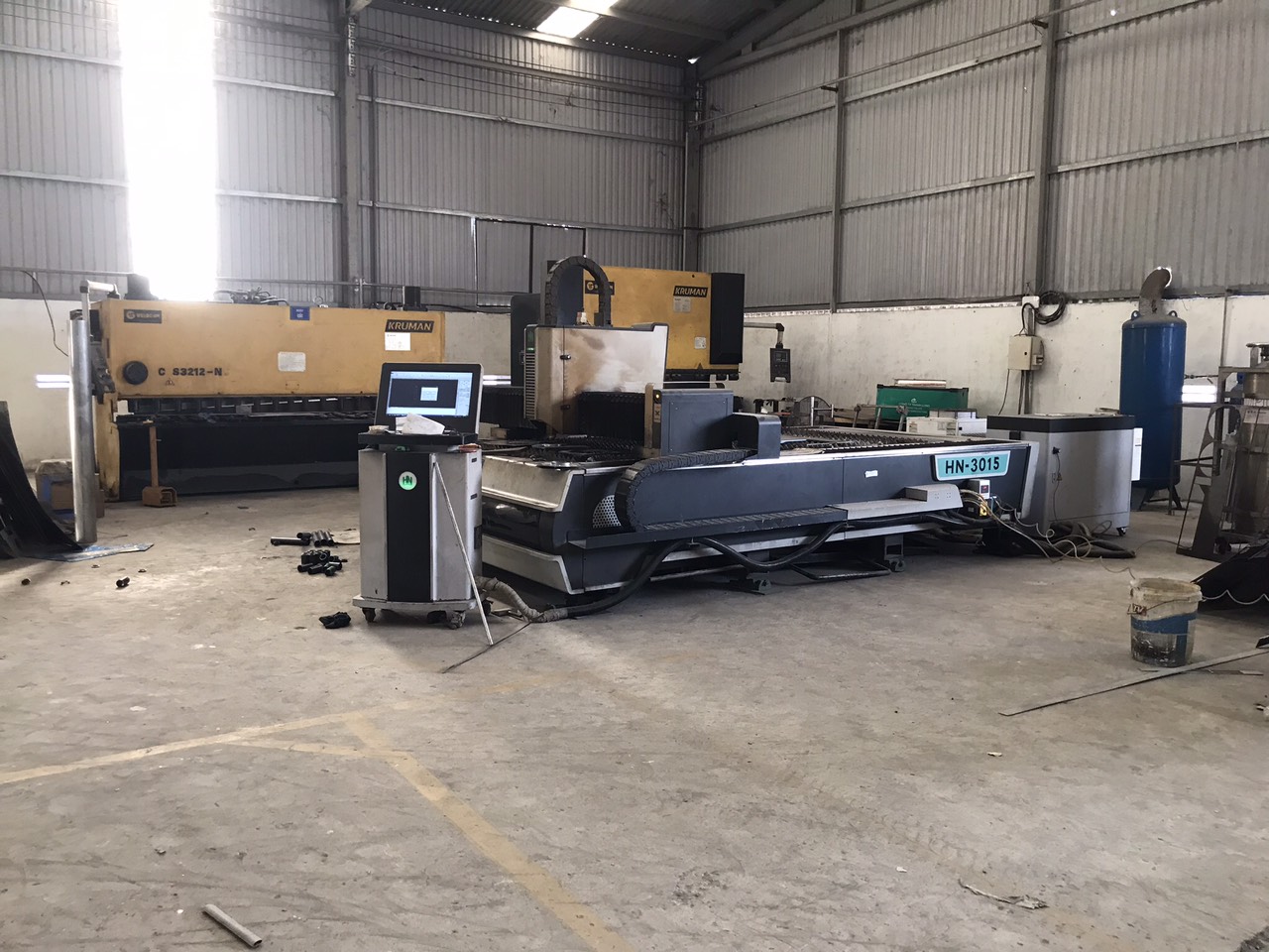
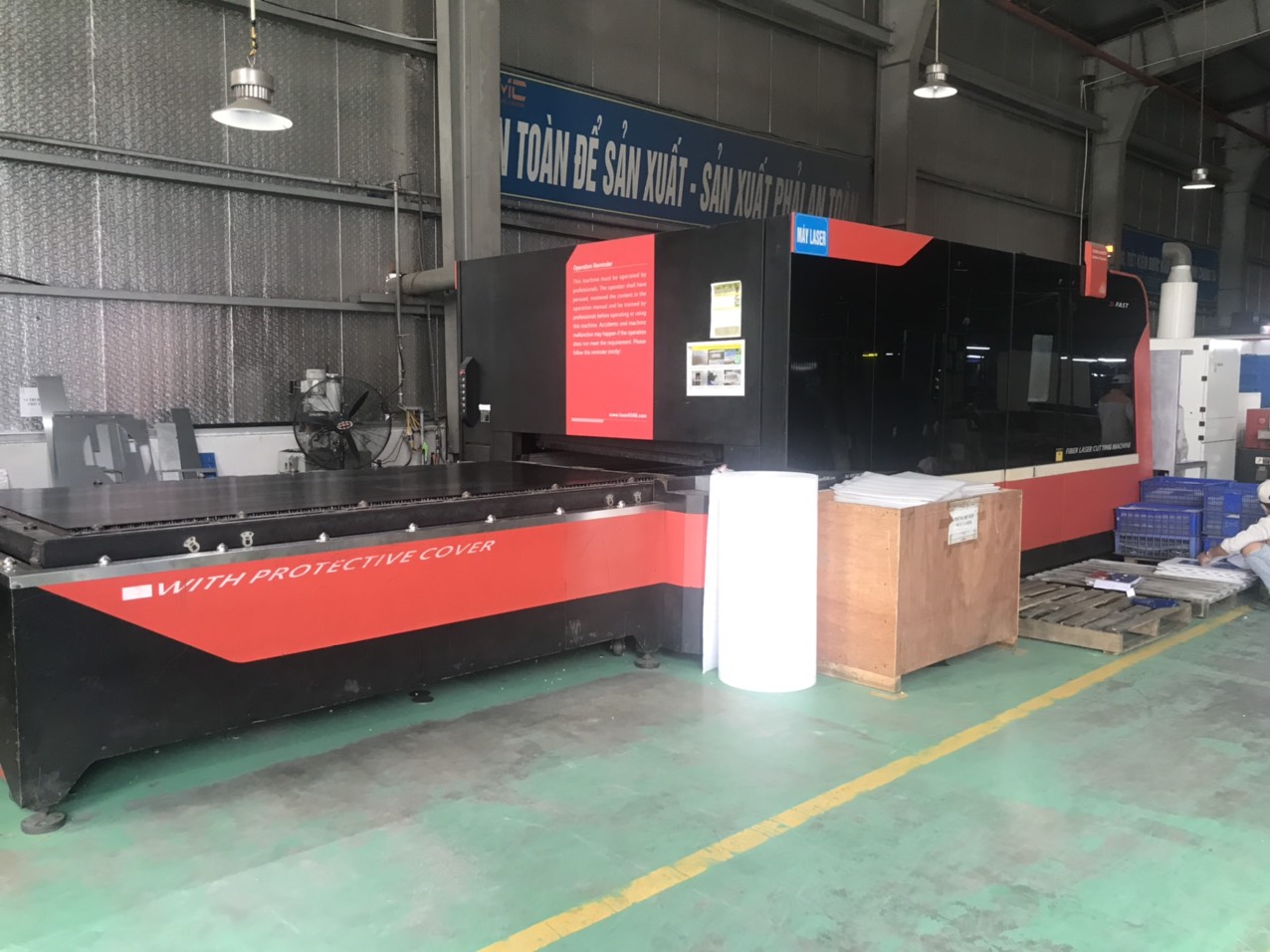
Every week, our project team reviews cutting method selections with clients who need custom sheet metal parts — and the laser versus plasma decision trips up even experienced buyers. sheet metal fabrication 1
The differences between laser and plasma cutting for sheet metal fabrication center on precision, material thickness range, cut quality, and cost. Laser cutting delivers tighter tolerances and cleaner edges on thin metals, while plasma cutting handles thicker plates faster and at lower initial investment, making each method ideal for different project requirements.
This guide breaks down each factor so you can match the right cutting process to your next custom project. We will cover precision, cost, thickness limits, and surface finish — the four areas where buyers ask us the most questions.
How do I determine if laser or plasma cutting offers the precision my custom project requires?
A recent bracket project taught our engineering team a hard lesson: a client's drawing called for ±0.05 mm on slot positions, and the supplier initially quoted plasma — which simply could not hold that tolerance.
To determine which process meets your precision needs, compare the tolerance each method achieves. Laser cutting holds tolerances as tight as ±0.030 mm with a narrow kerf width, while plasma cutting typically achieves ±0.1 mm with a wider kerf. Choose laser for intricate geometries and tight-tolerance features; choose plasma when tolerances above ±0.5 mm are acceptable.
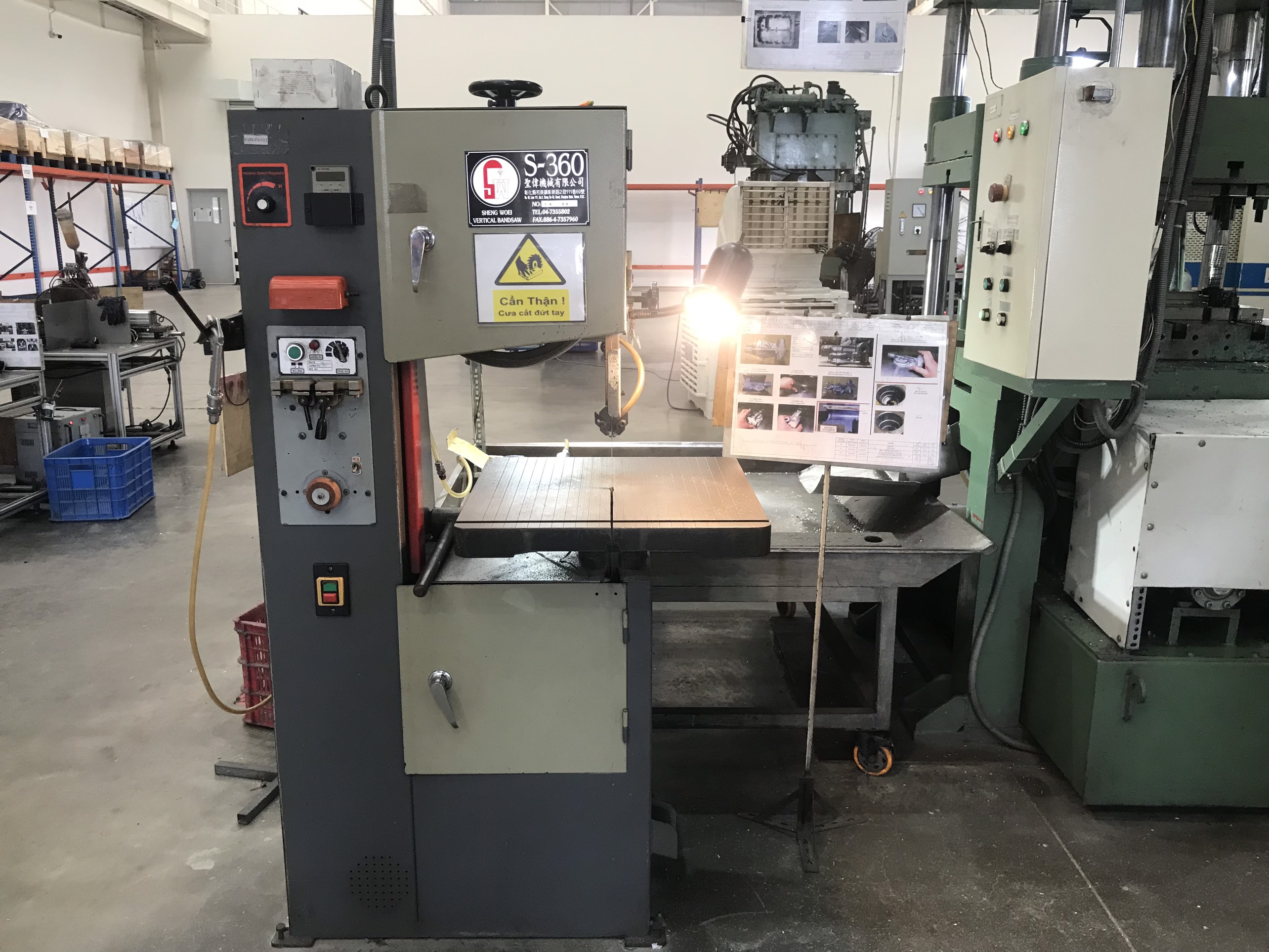
Understanding Tolerance in Practice
Tolerance is the allowable deviation from a nominal dimension. When our quality control team inspects a batch of custom mounting brackets, we measure every critical feature against the drawing. If the drawing says a hole must be 10.00 mm ±0.05 mm, every hole must fall between 9.95 mm and 10.05 mm.
Laser cutting 2 uses a focused beam of light energy to melt or vaporize metal. The beam is extremely narrow. This produces a thin kerf — often under 0.3 mm — and allows the CNC cutting machine 3 to trace complex contours with minimal deviation. The heat-affected zone 4 is small, so the surrounding material stays dimensionally stable.
Plasma cutting 5 uses an electrically conductive gas heated into a plasma arc. The arc is wider than a laser beam. The kerf is broader, and the heat input is higher. This means edges can shift slightly, and fine features like small holes or narrow slots lose definition.
Quick Tolerance Comparison
| Factor | Laser Cutting | Plasma Cutting |
|---|---|---|
| Typical tolerance | ±0.030 mm | ±0.1 mm or wider |
| Kerf width | 0.1–0.3 mm | 1.5–5.0 mm |
| Minimum hole diameter | Roughly equal to material thickness | 1.5× to 2× material thickness |
| Edge squareness | Excellent | Moderate |
| Heat-affected zone (HAZ) | Very small | Larger |
When Precision Matters Most
Parts with interlocking tabs, tight-fitting assemblies, or cosmetic edges almost always need laser cutting. We see this often with stainless steel brackets that have oval slots, small mounting holes, and folded flanges — exactly the kind of component shown in our product line. If the part will be visible in the final product, a clean laser-cut edge eliminates the need for post-processing 6 like grinding or deburring.
On the other hand, structural plates for frames, guards, or supports may only need ±0.5 mm. Plasma handles these jobs well. In our experience coordinating with fabrication shops across Vietnam and other Asian production hubs, plasma is the go-to choice for structural steel parts where fit-up tolerances are generous.
The decision also depends on geometry complexity. Laser cutting integrates smoothly with CAD/CAM software 7, reproducing intricate patterns and tight radii that plasma simply cannot replicate. If your drawing has features smaller than 3 mm, laser is your only realistic option.
Which cutting process will help me minimize lead times and reduce my overall sourcing costs?
One trade-off we weigh on nearly every quotation is cutting speed versus total cost — because the fastest cut does not always mean the cheapest part on your dock.
To minimize lead times and reduce sourcing costs, match the cutting process to your material thickness and volume. Laser cutting is faster and more cost-effective for thin sheets under 6 mm, often requiring zero post-processing. Plasma cutting lowers costs on thick plates over 16 mm due to higher cutting speed and lower operating costs at those thicknesses.
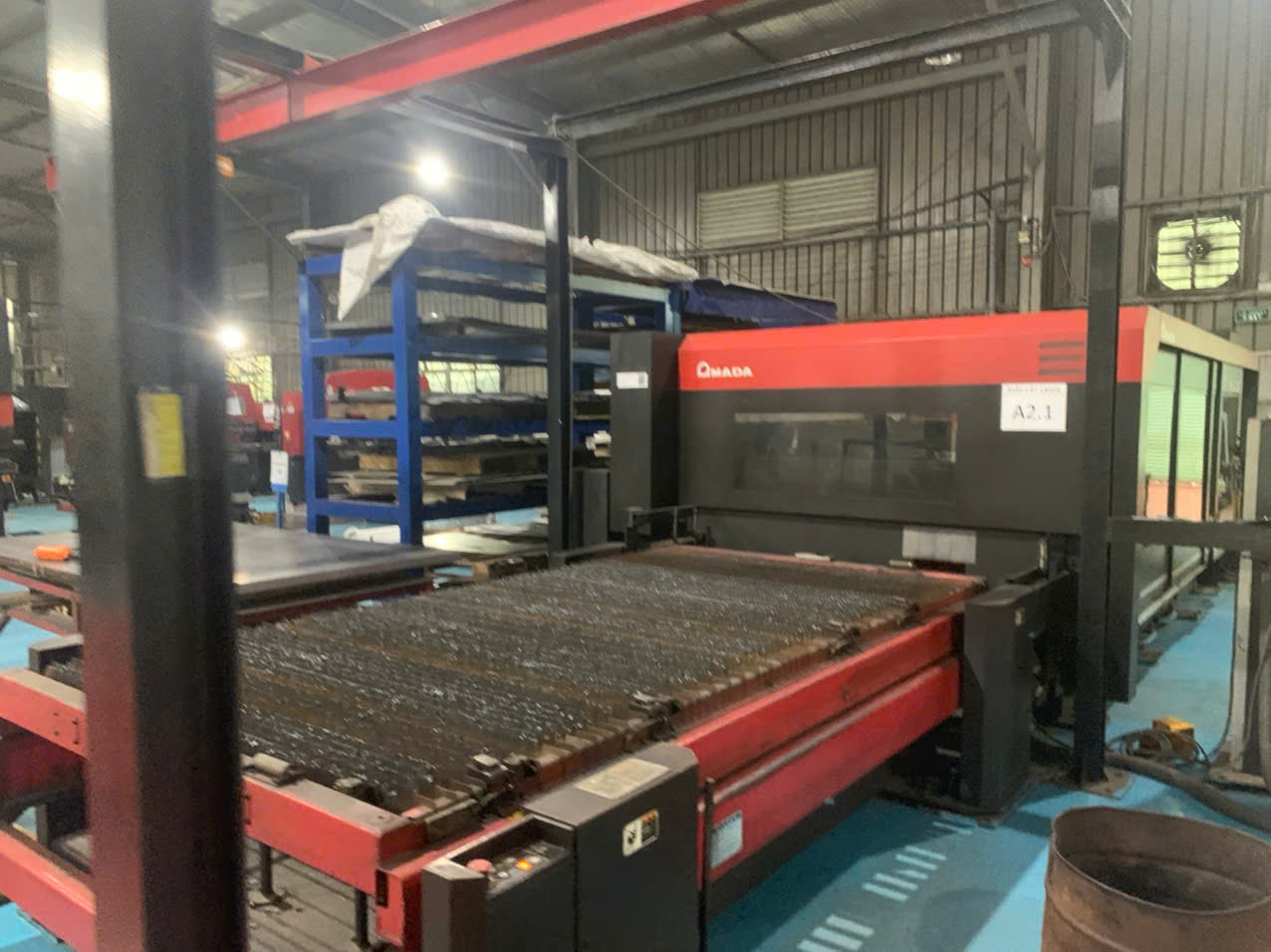
Cutting Speed by Thickness
Speed is not a single number. It changes with material thickness. For sheets thinner than 1.25 mm, fiber laser technology 8 can cut up to two times faster than plasma. But once you cross into thick plate territory — above 16 mm — plasma outpaces even high-power fiber lasers.
| Material Thickness | Faster Process | Speed Advantage |
|---|---|---|
| < 1.25 mm | Laser | ~2× faster than plasma |
| 1.25 mm – 6 mm | Laser | Moderately faster |
| 6 mm – 16 mm | Comparable | Depends on power and material |
| > 16 mm | Plasma | Significantly faster |
| > 25 mm | Plasma | Laser may not cut at all |
Breaking Down Total Cost
Buyers often focus on the per-part price, but total cost includes several layers. Here is how we break it down when helping U.S. clients source custom parts from Asia.
Initial investment: Laser machines cost significantly more to purchase. A high-power fiber laser system can cost several times what a comparable plasma table costs. This higher capital cost gets baked into per-part pricing, especially for low-volume orders.
Operating costs: Laser systems use less electricity per cut on thin materials. But for thick materials, plasma consumables — electrodes, nozzles, and shielding gas — are cheaper per meter of cut than the assist gas and lens replacements that lasers require.
Post-processing: This is where hidden costs live. Plasma cuts on thin or medium-thickness materials often produce dross and slag that must be ground off. That adds labor time. Laser cuts are typically clean enough to move straight to bending or welding. When we manage supplier workflows, eliminating a grinding step can shave one to two days off a production schedule.
Lead time impact: Faster cutting plus no secondary finishing means laser-cut parts reach the next operation sooner. For projects with tight delivery windows — a common pain point our clients raise — choosing laser on suitable thicknesses directly shortens the critical path. However, if your parts are 20 mm steel plates, forcing them onto a laser will slow you down and cost more.
A Practical Cost Scenario
Consider a batch of 500 mild steel brackets, 3 mm thick, with mounting holes and slots. Laser cutting completes the job in roughly half the machine time compared to plasma. No grinding is needed. The total cost per part is lower, and the batch ships faster.
Now consider 100 structural gusset plates, 25 mm thick, in mild steel. Plasma cuts them faster, the consumable cost per cut is lower, and the slightly rougher edge is acceptable because the plates will be welded into a frame. Choosing laser here would increase cost and extend lead time with no benefit to the end product.
How does the thickness of my sheet metal influence whether I should use laser or plasma cutting?
During a supplier audit at a fabrication plant in Vietnam last year, I watched the shop floor team switch between a fiber laser and a plasma table depending on the plate thickness arriving from the steel distributor — a hybrid workflow that made immediate sense.
Material thickness is the single biggest factor in choosing between laser and plasma cutting. Laser cutting excels on sheets up to about 25 mm, with optimal performance below 12 mm. Plasma cutting handles thicknesses from 3 mm up to 50 mm efficiently and dominates above 16 mm where it cuts faster and costs less per meter.
Thickness Limits Explained
Laser cutting works by focusing energy into a tiny spot. As material thickness increases, the beam must penetrate deeper. Beyond a certain point, the beam loses focus and cutting speed drops sharply. Most commercial fiber lasers max out around 25 mm for mild steel. Some ultra-high-power systems push further, but cost and quality trade-offs appear quickly.
Plasma cutting does not have the same limitation. The plasma arc carries enough energy to blow through thick plate efficiently. Plasma systems routinely cut 50 mm steel and can go beyond that with specialized equipment.
Material-Specific Thickness Ranges
Different metals behave differently under each process. Here is a practical reference we share with clients during the quoting phase.
| Material | Laser Max Thickness | Plasma Max Thickness | Recommended Crossover Point |
|---|---|---|---|
| Mild steel | 25.4 mm (1 in) | 50 mm (2 in) | ~16 mm — switch to plasma above this |
| Stainless steel | 19 mm (0.75 in) | 38 mm (1.5 in) | ~12 mm |
| Aluminum | 12.7 mm (0.5 in) | 38 mm (1.5 in) | ~10 mm |
| Copper / Brass | 6–10 mm | Limited by conductivity | Laser preferred for thin; plasma viable on thicker sections |
The Crossover Zone
Between 10 mm and 16 mm, both processes overlap. In this range, the decision depends on secondary factors: required cut quality, tolerance, volume, and budget.
For a run of 1,000 stainless steel parts at 10 mm thickness with cosmetic edges, laser is the clear winner. For 50 structural carbon steel plates at 14 mm with non-critical edges, plasma may offer a faster turnaround and lower cost.
Material Compatibility Beyond Thickness
Material compatibility matters too. Plasma cutting works only on electrically conductive metals — steel, stainless steel, aluminum, copper, and similar alloys. It cannot cut wood, plastic, or ceramic. Laser cutting handles a broader range of materials, including non-conductors, although for our custom metal parts business, this distinction rarely drives the decision.
One nuance worth noting: highly reflective metals like copper and brass were historically difficult for CO2 lasers. Modern fiber laser technology has largely solved this problem. Fiber lasers handle reflective metals much more effectively, narrowing the gap that plasma once exploited.
Hybrid Workshops Are the Trend
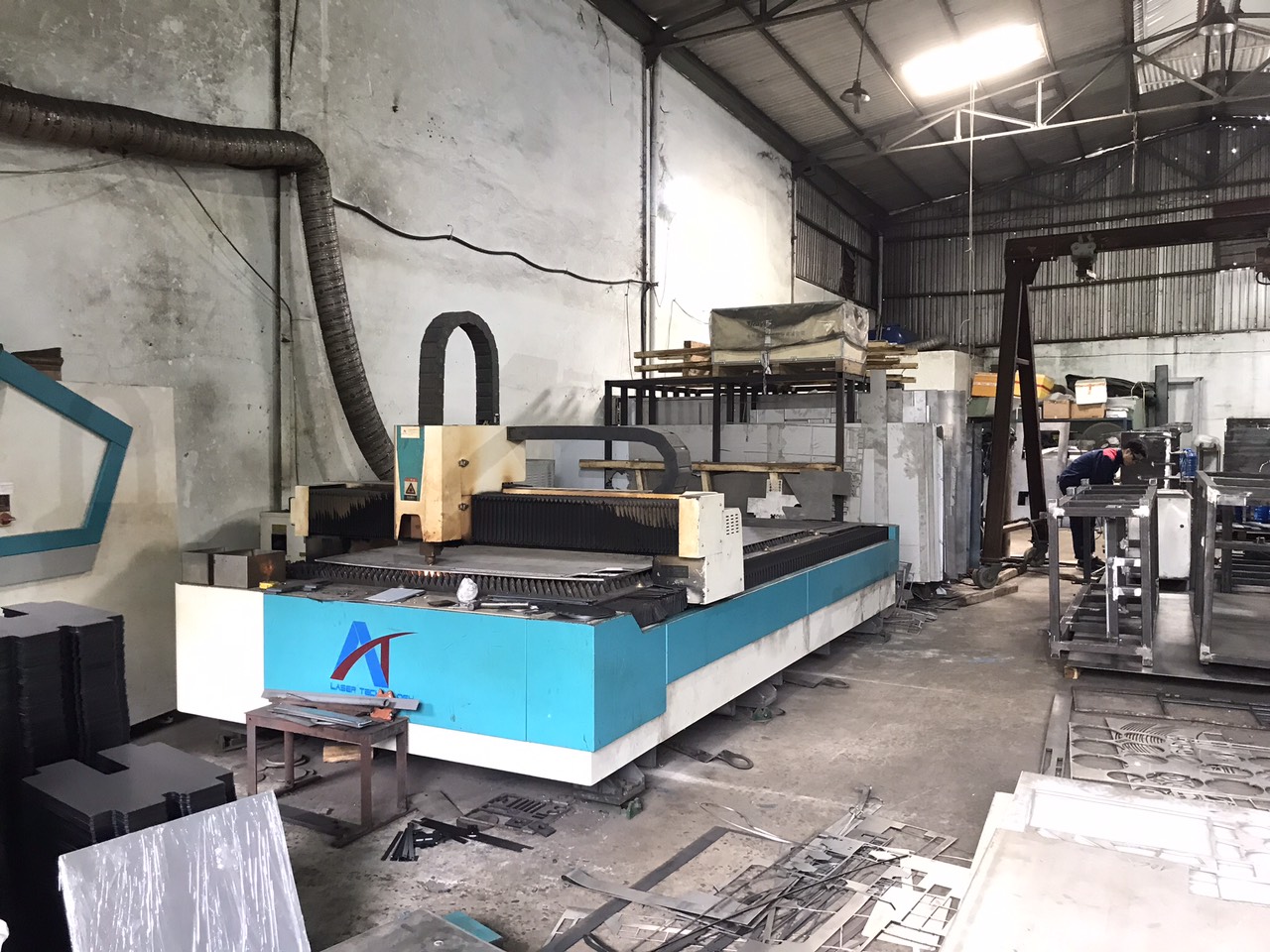
Many fabrication shops we partner with now operate both CNC cutting machines. They route thin, precision work to the laser and heavy structural work to the plasma table. This hybrid approach gives our clients access to the best tool for each job without being locked into a single process. When we coordinate multi-component orders — say, thin stainless brackets plus thick mild steel plates — we can split the work across both technologies within the same facility, keeping everything on schedule.
What impact will the choice between laser and plasma have on the final quality and finish of my parts?
A buyer we work with in the Midwest once rejected an entire shipment of plasma-cut flanges because the edges showed visible blueing and residual dross — a quality issue that would have been caught earlier if the cutting method had been specified during co-development.
Laser cutting produces smooth, burr-free edges with a surface roughness of 0.8–6 µm and a minimal heat-affected zone, so parts often need no post-processing. Plasma cutting leaves rougher edges with slag and potential thermal discoloration, typically requiring grinding or bead blasting before the part meets cosmetic or dimensional standards.
Edge Quality Side by Side
The edge left by a cutting process tells you a lot about what happens next in the production flow. Laser-cut edges are sharp, square, and smooth. You can run your finger along a laser-cut stainless steel edge and feel almost no roughness. This is why laser cutting is preferred for parts with visible edges, mating surfaces, or tight assembly fits.
Plasma-cut edges are rougher. The wider arc and higher heat input melt more material, and the assist gas blows it away less cleanly. The result is a surface with visible striations, possible dross on the bottom edge, and a larger heat-affected zone that can change the hardness and color of the metal near the cut.
Surface Finish Data
| Quality Metric | Laser Cutting | Plasma Cutting |
|---|---|---|
| Surface roughness 9 (Ra) | 0.8–6 µm | 12–25 µm (varies by thickness) |
| Edge squareness | < 1° deviation | 2°–5° deviation possible |
| Dross / slag | None or minimal | Common, especially on bottom edge |
| Thermal discoloration | Rare | Frequent on stainless steel |
| Burr presence | Minimal to none | Moderate to heavy |
The Thick-Material Exception
Here is a point that surprises many buyers. For material thickness above 16 mm, plasma can sometimes produce a smoother surface finish than fiber laser. At high thicknesses, the laser beam starts to diverge, creating striations and a rougher cut face. A well-tuned plasma system with quality consumables can actually outperform laser in edge smoothness on heavy plate. This is an important nuance when specifying cut quality for thick structural components.
Post-Processing Implications
When plasma cutting is used on parts that require a clean finish, secondary operations are almost always needed. Grinding removes dross and slag. Bead blasting evens out the surface texture. Deburring cleans up sharp edges. Each of these steps adds labor, time, and cost.
In our project management workflow, we factor post-processing into the production schedule from day one. If a client's drawing specifies a surface finish requirement — say, Ra 3.2 µm on cut edges — we know immediately that plasma will not meet that spec without extensive finishing. Laser delivers that quality straight off the machine. This "cut-and-go" efficiency is one of the strongest arguments for laser cutting on parts where cut quality matters.
Safety and Environmental Considerations
Both processes produce fumes and require ventilation. Plasma generates more particulate matter and noise, requiring robust extraction systems and hearing protection. Laser cutting produces fewer airborne particles but involves strict laser radiation safety protocols. From an energy standpoint, laser systems are generally more energy-efficient and produce less heat input into the surrounding environment. For clients with sustainability goals, this difference can influence the sourcing decision.
Conclusion
Choosing between laser and plasma cutting comes down to your part's thickness, tolerance, finish requirements, and budget — and our team helps clients navigate that decision on every custom project.
`
Frequently Asked Questions
How do I determine if laser or plasma cutting offers the precision my custom project requires?
A recent bracket project taught our engineering team a hard lesson: a client's drawing called for ±0.05 mm on slot positions, and the supplier initially quoted plasma — which simply could not hold that tolerance.
Which cutting process will help me minimize lead times and reduce my overall sourcing costs?
One trade-off we weigh on nearly every quotation is cutting speed versus total cost — because the fastest cut does not always mean the cheapest part on your dock.
How does the thickness of my sheet metal influence whether I should use laser or plasma cutting?
During a supplier audit at a fabrication plant in Vietnam last year, I watched the shop floor team switch between a fiber laser and a plasma table depending on the plate thickness arriving from the steel distributor — a hybrid workflow that made immediate sense.
Footnotes
1. Provides a comprehensive overview of sheet metal fabrication processes. ↩︎
2. Explains the fundamental principles and applications of laser cutting. ↩︎
3. Explains the function and components of CNC cutting machines. ↩︎
4. Defines the heat-affected zone and its impact on metal properties. ↩︎
5. Describes the working mechanism and applications of plasma cutting. ↩︎
6. Explains the necessity and types of post-processing in manufacturing. ↩︎
7. Clarifies the integration and purpose of CAD/CAM in manufacturing. ↩︎
8. Details the advantages and working principles of fiber laser technology. ↩︎
9. Replaced with an authoritative Wikipedia page directly defining surface roughness. ↩︎