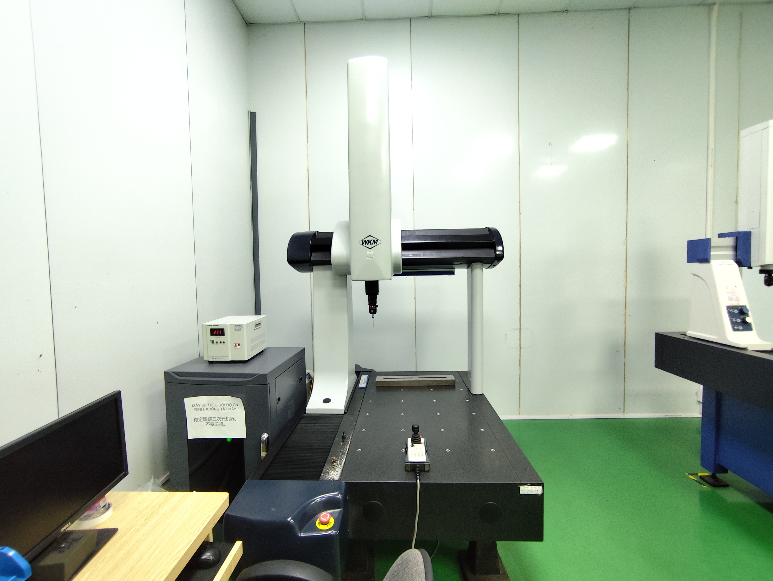
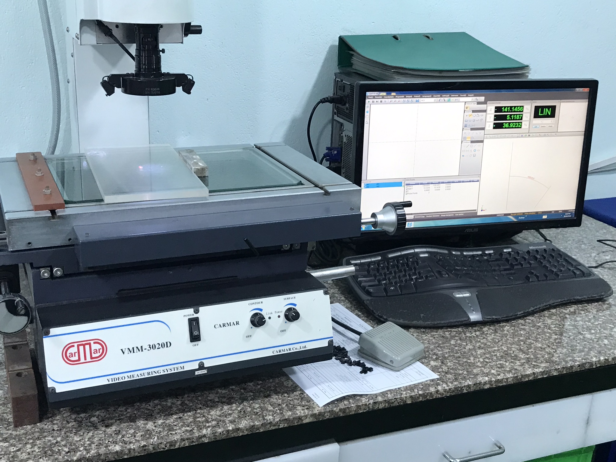
Last quarter, our quality team rejected an entire shipment of stamped brackets because the supplier measured them with uncalibrated equipment and no formal inspection plan — a costly mistake that delayed our client’s production line by three weeks.
Dimensional measurement and CMM inspection standards for stamping parts procurement include ASME B89.7.2 for measurement planning, ASME Y14.5 for Geometric Dimensioning and Tolerancing, ISO 10360 for CMM verification, ST1–ST11 and FT1–FT10 tolerance grades, and quality frameworks like IATF 16949 and ISO 9001 to ensure dimensional accuracy and supplier compliance.
This guide breaks down each standard, explains how to specify the right tolerances, and shows you what to demand from your stamping supplier. Let’s walk through the details section by section.
How do I know which CMM inspection standards my stamping supplier should follow?
A few years ago, one of our U.S. clients asked us to audit a stamping supplier in Vietnam. The supplier had a CMM machine in the corner of the shop floor — but no written measurement plan and no proof of annual calibration. That single finding saved our client from months of quality headaches.
Your stamping supplier should follow ASME B89.7.2 for dimensional measurement planning, ISO 10360 for CMM performance verification, and ASME Y14.5 for interpreting geometric tolerances. For automotive parts, IATF 16949 certification is essential; for aerospace, AS9100 aerospace standards apply.

The Core Standards You Need to Know
Not all CMM inspection standards serve the same purpose. Some govern how the machine itself is tested. Others govern how measurements are planned. And a third group defines how tolerances appear on your drawing. You need your supplier to follow all three layers.
ASME B89.7.2 1 is the standard for dimensional measurement planning. It was reaffirmed in 2024 and remains the current active guideline. It requires your supplier to document every detail: what equipment they use, what procedures they follow, what environmental conditions exist in the lab, and what the measurement uncertainty budget looks like. Without this plan, CMM data is just numbers without context.
ISO 10360 2 covers the CMM machine itself. It defines how to verify the volumetric accuracy and probe performance of a coordinate measurement machine 3. If your supplier cannot show you a current ISO 10360 verification report, you have no reason to trust their dimensional data.
ASME Y14.5 4 is the Geometric Dimensioning and Tolerancing standard. It tells everyone — your designers, your supplier's programmers, and your quality inspectors — how to interpret the symbols on a drawing. Without alignment on GD&T, your supplier might measure the right feature in the wrong way.
Matching Standards to Your Industry
| Industry | Primary Quality Framework | Key CMM Standards | Additional Requirements |
|---|---|---|---|
| Automotive | IATF 16949 certification | ASME B89.7.2, ISO 10360 | Production Part Approval Process 5 (PPAP), Gage R&R study |
| Aerospace | AS9100 aerospace standards | ASME B89.7.2, ISO 10360 | First Article Inspection per AS9102 6, full traceability |
| General Industrial | ISO 9001 | ASME B89.7.2, ISO 10360 | Statistical Process Control data optional |
| Medical Devices | ISO 13485 | ASME B89.7.2, ISO 10360 | Validation documentation, risk-based inspection |
When we conduct supplier audits in Vietnam or other Asian countries, we check for three things first: a valid calibration certificate for the CMM, a documented measurement plan referencing ASME B89.7.2, and evidence that the operator has been trained on GD&T interpretation. These three checks eliminate most measurement-related disputes before they start.
Why Traceability Matters
Every measurement your supplier takes must be traceable to the SI unit of length. This is not optional. ASME B89.7.2 explicitly requires it. In practice, this means the CMM's calibration must link back to a national metrology institute through an unbroken chain of comparisons. If your supplier uses a reference artifact that has no calibration certificate, the entire inspection is unreliable.
Our team has seen suppliers use gauge blocks that expired two years ago. We have seen CMM probes that were never qualified after replacement. These are the silent risks in stamping parts procurement that only a structured audit catches. When we manage the metrology and calibration process on behalf of our clients, we schedule verification checks at fixed intervals and require the supplier to maintain a calibration log that we can review remotely.
What dimensional tolerances should I specify when sourcing custom stamped parts?
The hardest lesson I learned in this business is that vague tolerance specs on a purchase order always come back as rejected parts on the receiving dock. A client once wrote "general tolerances apply" on a bracket drawing, and the supplier interpreted that as the loosest possible grade — resulting in parts that would not fit in the assembly.
When sourcing custom stamped parts, specify ST1–ST11 tolerance grades for flat features and FT1–FT10 for formed features. Use ISO 2768 general tolerances (medium or fine class) for non-critical dimensions, and apply ASME Y14.5 GD&T callouts for all functional surfaces, holes, and bend angles.

Understanding ST and FT Tolerance Grades
Stamping tolerance grades are divided into two families. Flat stamping parts use ST grades from ST1 (tightest) to ST11 (loosest). Formed stamping parts use FT grades from FT1 (tightest) to FT10 (loosest). These grades directly affect die complexity, production speed, and cost.
| Grade Type | Range | Highest Precision | Lowest Precision | Typical Application |
|---|---|---|---|---|
| ST (Flat Parts) | ST1–ST11 | ST1 | ST11 | Blanking, piercing, flat profiles |
| FT (Formed Parts) | FT1–FT10 | FT1 | FT10 | Bending, drawing, forming operations |
Choosing the right grade is a trade-off. ST1 or FT1 means tighter dies, slower production, and higher cost. ST11 or FT10 means looser fits and cheaper tooling. For most mounting brackets and structural stamped parts, mid-range grades like ST5–ST7 or FT4–FT6 offer a good balance between function and cost.
The Role of ISO 2768 General Tolerances
For dimensions that do not have a specific tolerance callout on the drawing, ISO 2768 7 general tolerances fill the gap. This standard defines four classes: fine (f), medium (m), coarse (c), and very coarse (v). The most common choice for stamped parts is ISO 2768-mK, which applies medium tolerances for linear dimensions and class K for geometrical tolerances.
Here is why this matters for procurement: if your drawing title block says "ISO 2768-mK" but your supplier defaults to "ISO 2768-cL," every un-toleranced dimension on the part just got looser. We always recommend that our clients explicitly state the ISO 2768 class in both the drawing title block and the purchase order. This removes ambiguity.
Critical Design Rules That Affect Tolerance
Sheet metal fabrication tolerances are not just about numbers on a drawing. Physical material behavior creates hard limits.
| Design Feature | Rule | Example |
|---|---|---|
| Minimum hole diameter (ductile metals like aluminum) | ≥ 1.2× material thickness | 1.0 mm sheet → min. 1.2 mm hole |
| Minimum hole diameter (high-tensile metals like stainless steel) | ≥ 2× material thickness | 1.0 mm sheet → min. 2.0 mm hole |
| Minimum slot width | ≥ 1.5× material thickness | 1.0 mm sheet → min. 1.5 mm slot |
| Angular tolerance on bends | Typically ±1° | Standard for single-hit forming |
| Expected burr height | Up to 10% of material thickness | 1.0 mm sheet → up to 0.1 mm burr |
When we review a client's drawings before sending them to a supplier, we flag any dimensions that violate these rules. A hole specified at 0.8 mm in 1.0 mm stainless steel will not stamp cleanly. Catching this before production saves weeks of rework.
Tolerance Stack-Up in Multi-Bend Parts
Parts with multiple bends accumulate error. Each bend introduces its own angular and positional tolerance. If a bracket has three 90° bends, the final position of the last flange depends on the accuracy of every bend before it.
This is where Geometric Dimensioning and Tolerancing 8 becomes essential. Instead of tolerancing each bend independently, you can use a profile tolerance on the final feature that controls the cumulative effect. Our engineering team often works with clients during the co-development phase to restructure tolerance callouts so they reflect functional requirements — not just manufacturing convenience.
How can I verify a supplier's measurement equipment meets my quality requirements?
During a factory audit in southern China last year, I walked into a temperature-controlled metrology lab that looked impressive — until I checked the calibration stickers. Two out of three CMMs had expired certificates. The third had a certificate from an unaccredited lab. Equipment alone means nothing without proper verification.
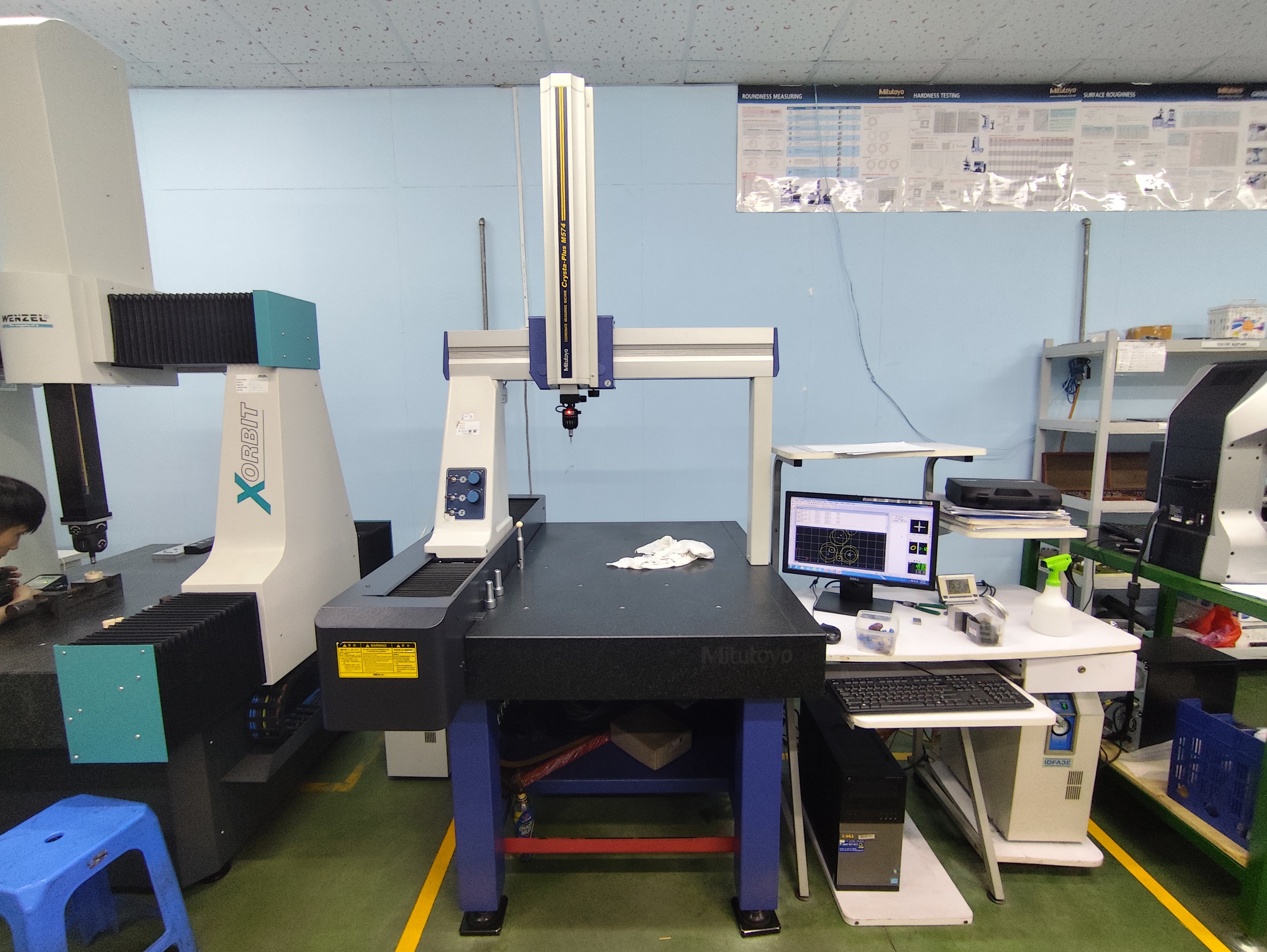
Verify your supplier's measurement equipment by requesting current ISO 10360 performance verification reports for all CMMs, confirming calibration traceability to national standards, reviewing Gage R&R study results for repeatability and reproducibility, and checking that the metrology lab maintains controlled environmental conditions.
What ISO 10360 Verification Tells You
ISO 10360 is a multi-part standard that defines how to test a CMM's accuracy. It covers volumetric length measuring error, probing error, and scanning probing error. When a supplier provides an ISO 10360 report, you can see the actual measured performance of their machine compared to the manufacturer's specification.
If the CMM's measured error exceeds its specification, every part inspected on that machine is suspect. We require every supplier in our network to provide a current ISO 10360 report before they inspect any production parts for our clients. This is non-negotiable.
The Gage R&R Study
A Gage R&R study (Gage Repeatability and Reproducibility) tells you whether the measurement system — including the CMM, the fixture, and the operator — can consistently produce the same result. Repeatability measures variation when one operator measures the same part multiple times. Reproducibility measures variation when different operators measure the same part.
For the Production Part Approval Process in automotive supply chains, a Gage R&R study is mandatory. The measurement system's total variation should be less than 10% of the part tolerance for the system to be considered acceptable. Between 10% and 30% may be conditionally acceptable. Above 30% means the measurement system cannot reliably distinguish good parts from bad parts.
Environmental Controls
CMMs are sensitive to temperature. A standard CMM is calibrated at 20°C (68°F). If the measurement lab runs at 25°C or fluctuates throughout the day, thermal expansion can introduce errors that exceed the part tolerance. Advanced CMM software includes temperature compensation algorithms, but these are only effective if the temperature sensors are properly placed and calibrated.
When we audit a supplier's metrology facility, we check room temperature logs, air conditioning reliability, and whether the CMM is isolated from shop floor vibrations. These environmental factors are easy to overlook but critical to measurement reliability.
Contact vs. Non-Contact Measurement
| Method | Best For | Limitations | Accuracy Level |
|---|---|---|---|
| Tactile CMM (contact probe) | Flatness, perpendicularity, hole position | Slow for complex surfaces; may mark soft materials | Micrometer (µm) level |
| 3D laser scanning (non-contact) | Complex curves, full surface topology, springback analysis | Lower point accuracy than tactile; sensitive to surface reflectivity | Tens of micrometers |
| Go/No-Go gauges | High-volume production floor checks | No data capture; pass/fail only | Dependent on gauge tolerance |
| Profilometer | Surface roughness (Ra, Rz) | Measures roughness only, not dimensions | Sub-micrometer |
The optimal strategy is a hybrid approach. Use tactile CMM for First Article Inspection and critical geometric features. Use 3D scanning for complex formed surfaces and springback compensation analysis on high-strength steel stampings. Use go/no-go gauges for routine production monitoring where CMM would create a bottleneck.
Our quality engineers often recommend that clients require suppliers to use standardized DMIS code for CMM programs. DMIS (Dimensional Measurement Interface Standard 9) allows seamless transfer of inspection programs between the supplier's CMM and the buyer's quality lab. This means you can re-run the same program on your own equipment to verify the supplier's results — a powerful cross-check that builds trust in the data.
What inspection reports should I request to confirm dimensional accuracy before shipment?
The question I hear most from procurement managers is simple: "What paperwork do I actually need before I approve shipment?" It sounds straightforward, but the answer depends on whether you are doing a first production run or a repeat order, and whether your end customer requires automotive-level documentation.
Request a First Article Inspection report with full CMM dimensional data, a PPAP Level 3 submission for automotive parts, Statistical Process Control charts for critical dimensions, material certificates, and a CAD model comparison report to confirm dimensional accuracy before approving shipment.
First Article Inspection Reports
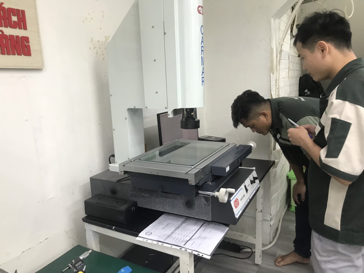
A First Article Inspection report is your first line of defense. It documents the measured value of every dimension on the drawing for the first production parts. The report compares each measured value to the specified tolerance and flags any out-of-spec conditions.
For aerospace programs, AS9102 defines the exact format of the First Article Inspection report. For other industries, the format may vary, but the content should always include the drawing revision, the measurement equipment used, the environmental conditions during inspection, and the pass/fail status of every dimension.
PPAP Level 3 for Automotive
The Production Part Approval Process has five submission levels. Level 3 is the most common requirement for stamped automotive parts. It includes:
- Dimensional results (full CMM layout)
- Material test reports
- Process flow diagram
- Control plan
- Gage R&R study results
- Statistical Process Control data for critical characteristics
- Appearance approval report (if applicable)
When we manage the PPAP process for our clients, we review every element before submission. We have caught errors in control plans where the supplier listed the wrong measurement frequency, or where the Gage R&R showed excessive operator variation that needed to be resolved before production could proceed.
Statistical Process Control Data
Static pass/fail inspection reports tell you whether the parts you have are good. Statistical Process Control tells you whether the process that made them is stable and capable. SPC charts — typically Xbar-R or Xbar-S charts — trend critical dimensions over time and reveal tool wear, press drift, or material variation before they result in out-of-spec parts.
We increasingly see procurement standards requiring real-time trending analysis rather than just batch inspection. This shifts the focus from "detecting bad parts" to "preventing bad parts." It also provides early warning when a die needs maintenance, which reduces the risk of delivery delays — one of the most common pain points our U.S. clients face with Asian suppliers.
CAD Model Verification
The industry is moving toward Model-Based Definition 10, where the 3D CAD file serves as the primary design authority. Instead of comparing CMM data to a 2D drawing, the supplier compares it directly to the CAD model. This eliminates discrepancies that arise from 2D interpretation errors and speeds up the approval process for complex geometries.
When requesting inspection reports, ask your supplier to include a color-map deviation plot. This is a visual representation of the CMM or 3D scan data overlaid on the CAD model. Green areas are within tolerance. Yellow areas are approaching the limit. Red areas are out of spec. It gives you an instant visual assessment that complements the numerical data.
Closed-Loop Metrology
An emerging trend in advanced stamping operations is closed-loop metrology. In this approach, CMM data feeds directly into die-adjustment software to automate corrections to the stamping press parameters. While not yet standard in most supply chains, it represents the direction the industry is heading. If your supplier offers this capability, it signals a high level of process maturity and commitment to continuous improvement.
Conclusion
Clear dimensional measurement and CMM inspection standards are the foundation of successful stamping parts procurement. Specify your tolerance grades, demand ASME B89.7.2-compliant measurement plans, verify equipment calibration, and require comprehensive inspection reports before every shipment. To build a robust framework for evaluating parts upon receipt, learn how to establish effective incoming inspection standards for stamping parts. Additionally, understanding the common quality certifications for sheet metal fabrication will help you pre-qualify suppliers and reduce risk throughout your supply chain.
Frequently Asked Questions
How do I know which CMM inspection standards my stamping supplier should follow?
A few years ago, one of our U.S. clients asked us to audit a stamping supplier in Vietnam. The supplier had a CMM machine in the corner of the shop floor — but no written measurement plan and no proof of annual calibration. That single finding saved our client from months of quality headaches.
What dimensional tolerances should I specify when sourcing custom stamped parts?
The hardest lesson I learned in this business is that vague tolerance specs on a purchase order always come back as rejected parts on the receiving dock. A client once wrote "general tolerances apply" on a bracket drawing, and the supplier interpreted that as the loosest possible grade — resulting in parts that would not fit in the assembly.
How can I verify a supplier's measurement equipment meets my quality requirements?
During a factory audit in southern China last year, I walked into a temperature-controlled metrology lab that looked impressive — until I checked the calibration stickers. Two out of three CMMs had expired certificates. The third had a certificate from an unaccredited lab. Equipment alone means nothing without proper verification.
Footnotes
1. Official ASME standards body governing dimensional measurement planning requirements referenced throughout the article. ↩︎
2. ISO is the standards organization that publishes ISO 10360 for CMM performance verification. ↩︎
3. Background reference explaining how coordinate measurement machines function for dimensional inspection. ↩︎
4. ASME publishes Y14.5, the authoritative GD&T standard referenced for interpreting drawing tolerances. ↩︎
5. Background explanation of the automotive PPAP submission framework mentioned for Level 3 requirements. ↩︎
6. SAE International publishes AS9102, the aerospace First Article Inspection reporting standard. ↩︎
7. ISO is the source organization for the ISO 2768 general tolerance classes discussed here. ↩︎
8. Background concept explaining the GD&T system used to control multi-bend tolerance stack-up. ↩︎
9. Provides background on DMIS, the standardized format for transferring CMM inspection programs. ↩︎
10. Explains the MBD approach where CAD models replace 2D drawings as the design authority. ↩︎