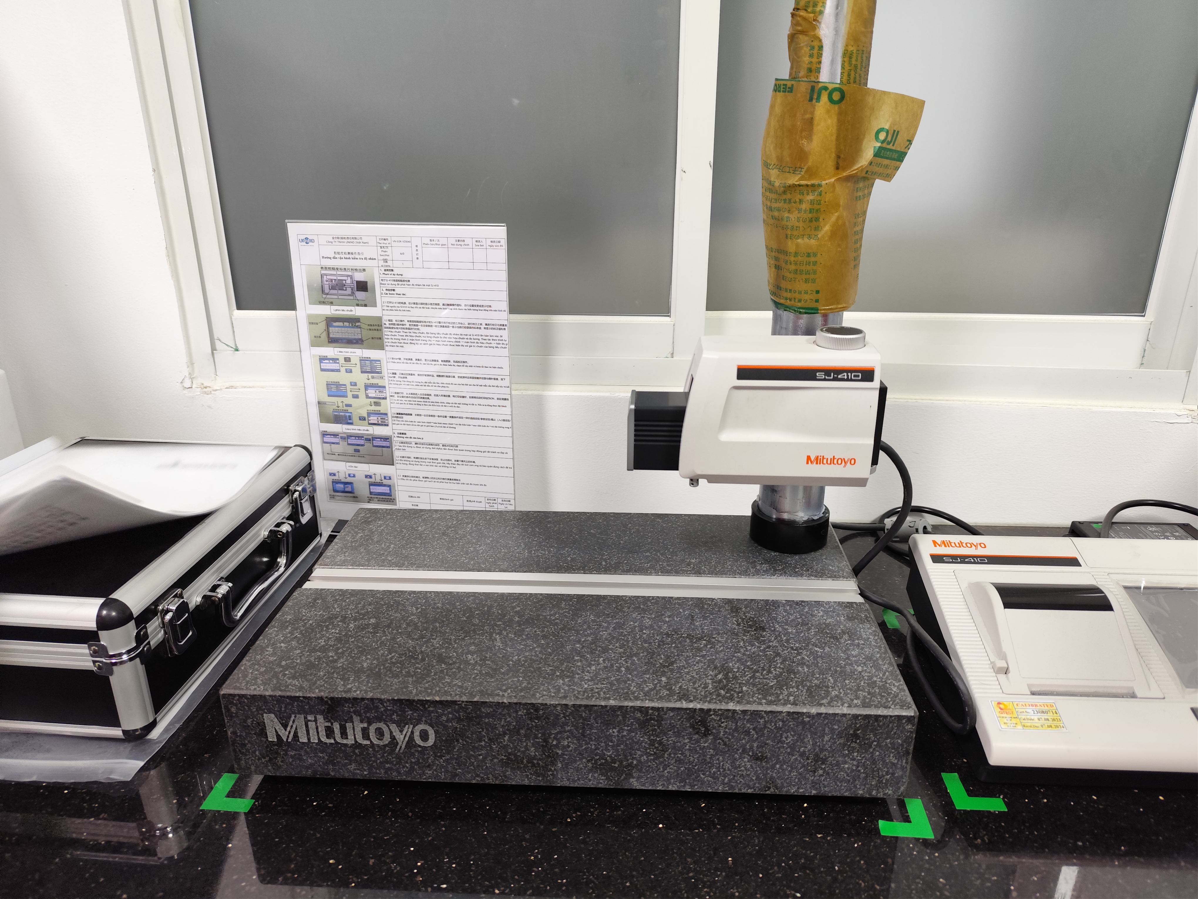
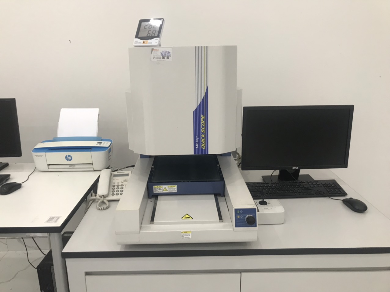
A few months ago, our quality team rejected an entire shipment of stamped brackets because the supplier measured formed features from the wrong reference surface — the outside instead of the inside. The parts were actually within tolerance, but misaligned measurement conventions triggered false rejects, delayed the project by three weeks, and cost our client thousands. That experience drove us to overhaul how we specify dimensional measurement and CMM standards for every stamping project we manage.
Dimensional measurement and CMM standards for stamping parts include ISO 2768 for general tolerances, ASME Y14.5 or ISO 1101 for GD&T, ASME B89.7.2 for CMM measurement planning, and DIN 6930 for stamping-specific tolerance classes. These standards together define how stamped features are dimensioned, measured, and accepted.
Getting these standards right is not optional. They determine whether your parts fit during assembly, pass incoming inspection, and meet safety requirements. Below, I walk through exactly which measurement points matter, what tolerances to expect, how to request proper CMM reports, and which industry standards your supplier should follow.
How do I know which CMM measurement points matter most for my stamping parts?
One lesson we learned early in our supply chain work is that measuring every single dimension on a stamped bracket wastes time and money without improving quality. The real skill is identifying which dimensions are Critical-to-Quality — the ones that affect fit, function, safety, or assembly.
The CMM measurement points that matter most are your Critical-to-Quality (CTQ) dimensions: hole positions, bend angles, formed heights, contact surfaces, coplanarity, and any feature that directly affects fit or function during assembly. Focus your CMM inspection plan on these rather than measuring every dimension.
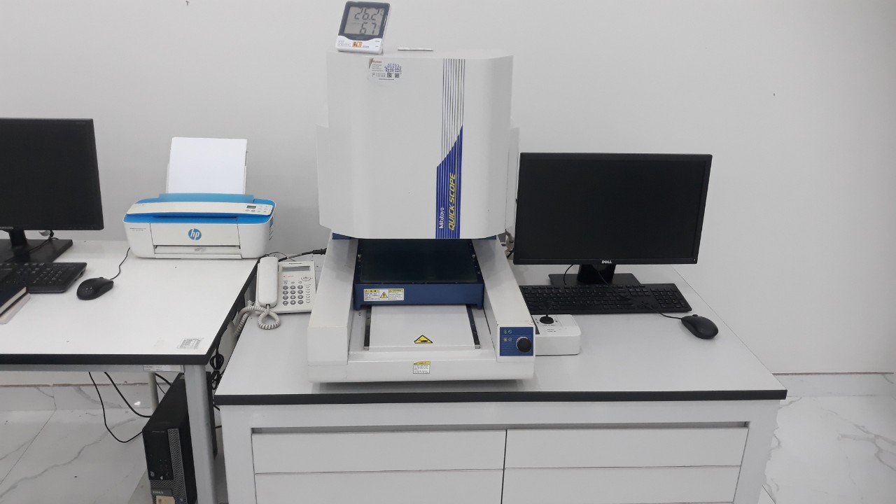
What Are CTQ Dimensions in Stamping?
CTQ dimensions are the specific features on a stamped part that must be controlled to ensure the part works as intended. For a mounting bracket like the ones we source for U.S. clients, typical CTQ dimensions include:
- Hole position and diameter (for bolt alignment)
- Bend angle (typically ±1° tolerance)
- Formed leg length and height
- Flatness of mounting surfaces
- Coplanarity of contact pads
- Edge-to-hole distances
When we set up a new stamping project, our engineers review the 3D CAD model and the assembly context. We ask: "If this feature is out of tolerance, does the part fail to assemble or function?" If the answer is yes, it goes on the CTQ list.
Inside vs. Outside Measurement Conventions
This is where many suppliers and buyers get tripped up. Stamped parts have a shear band (the clean-cut portion) and a breakaway zone (the rough, fractured portion). The measurement convention depends on whether you are measuring a blanked outline or a punched hole.
| Feature Type | Measurement Reference | CMM Probe Target |
|---|---|---|
| Blanked outline (external) | Maximum material condition (larger end) | Measure at the shear band / die side |
| Punched hole (internal) | Minimum material condition (smaller end) | Measure at the shear band / punch side |
| Formed feature (bend) | Inside surface of the bend | Dimension to the inside, not outside |
Getting this wrong is the single most common cause of false rejects in stamping inspection. When our Vietnam office conducts final inspection, we explicitly train CMM operators on these conventions before the first measurement run.
Building a CTQ-Focused Inspection Plan
A full inspection of every dimension makes sense for First Article Inspection — when you verify the first parts off a new die. But for routine production, a CTQ-focused sampling plan is far more cost-effective. We typically structure inspection plans in two tiers:
| Inspection Stage | Scope | Frequency |
|---|---|---|
| First Article Inspection (FAI) | 100% of all dimensions on the drawing | First piece from new or modified tooling |
| Production inspection | CTQ dimensions only | Per AQL sampling plan or 100% on critical features |
| Periodic audit | Full dimensional layout | Every 5,000–10,000 pieces or per agreed interval |
This approach reduces inspection cost by 40–60% compared to measuring everything on every part, while maintaining tight control over the features that actually matter. Our clients in the U.S. consistently prefer this structure because it gives them data where they need it without inflating piece price.
What dimensional tolerances should I expect from a qualified stamping supplier?
During a recent project review with a U.S. purchasing manager, the question came up: "Your competitor says they can hold ±0.001 inches on every feature. Can you?" My honest answer was no — and neither can they, at least not on formed features from a progressive die. Tolerance expectations must be grounded in material physics, not marketing claims.
A qualified stamping supplier typically holds ±0.002 inches on high-precision holes and edges, ±0.005 inches on linear dimensions up to 1 inch, and ±1° on bend angles. Tolerances widen with material thickness, part complexity, and distance from datum features. Always verify capabilities against specific standards like DIN 6930 Class m or ISO 2768.

Tolerance Expectations by Feature Type
Tolerances in stamping are not uniform. A punched hole can be held much tighter than a formed leg length, because punching is a single shearing action while forming involves springback 2, tool deflection, and material variability.
| Feature | Typical Tolerance | Key Drivers |
|---|---|---|
| Punched hole diameter | ±0.002" | Punch/die clearance, material thickness |
| Hole position | ±0.005" | Strip feeding accuracy, pilot pin condition |
| Edge-to-edge (blanked) | ±0.005" (0–1") | Die sharpness, material temper |
| Formed bend angle | ±1° | Springback, material grade, bend radius |
| Formed leg length | ±0.010" | Die condition, material thickness, bend radius |
| Overall length >4" | ±0.020" or more | Cumulative tolerance stack-up |
| Burr height | ~10% of material thickness | Die wear, clearance |
These numbers represent what a well-maintained tool in a controlled process can achieve. Our quality engineers use these as baseline expectations when we evaluate supplier capabilities during audits.
What Drives Tolerance Tightness or Looseness?
Several material and process factors determine how tight a tolerance your supplier can realistically hold:
Material thickness — Thinner materials are more prone to distortion. Features on thin stock (under 0.5 mm) require careful handling and possibly tighter die clearances.
Material temper and grade — Hard materials like stainless steel spring back more aggressively on bends. Ductile materials like aluminum allow tighter hole diameter tolerances but are more prone to burring.
Tool wear — A die that has run 500,000 cycles will not hold the same tolerances as a new tool. Predictive die maintenance using CMM-derived trend data helps schedule resharpening before parts drift out of spec.
Feature location relative to bends — Holes near bends (closer than 2× material thickness from the bend radius) are subject to distortion. Holes far from locating features accumulate positional error.
Number of forming stations — Each additional bend in a progressive die adds angular tolerance stack-up. A part with three sequential bends must account for ±1° at each, potentially creating significant deviation at the far end.
Design Rules That Affect Measurable Tolerances
When we co-develop parts with our clients, we apply sheet metal fabrication 3 standards and design-for-manufacturability rules that directly influence what the CMM will measure:
- Hole diameter minimums: ≥1.2× material thickness for ductile materials, ≥2× for high-tensile materials
- Hole spacing: ≥1.5× material thickness center-to-center
- Holes near bends: ≥2× material thickness from the bend radius
- Formed leg length: ≥2.5× material thickness beyond the bend
- Notch and slot width: ≥1.5× material thickness
Violating these rules creates features that cannot be measured reliably because the geometry itself is distorted. We catch these issues during design review — before tooling is cut — which is far cheaper than discovering them during CMM inspection.
Can I request a full CMM inspection report before my parts ship?
A few years back, one of our U.S. clients received stamped post-base brackets that looked fine visually but failed during assembly — the mounting holes were shifted 0.008 inches from nominal. There was no pre-shipment dimensional report. That single incident cost more in rework and air freight than a year's worth of CMM inspections. Since then, we require CMM reports on every critical shipment.
Yes, you can and should request a full CMM inspection report before stamping parts ship. A proper report includes actual vs. nominal values for all CTQ dimensions, GD&T callouts (flatness, perpendicularity, profile), pass/fail status, measurement uncertainty, and traceability to calibrated equipment per ASME B89.7.2.
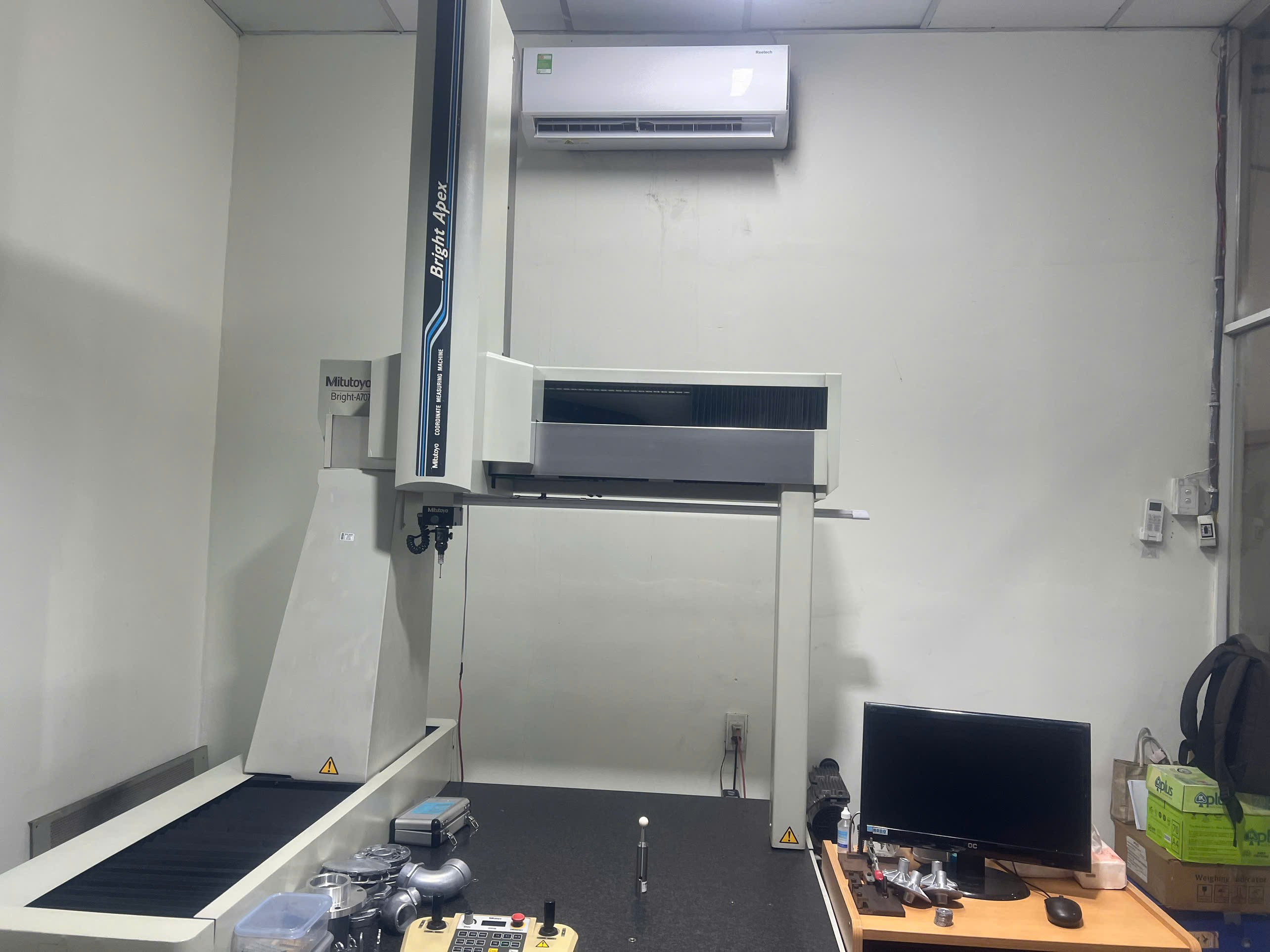
What Should a CMM Report Include?
A complete CMM inspection report is more than a list of numbers. It is a controlled document that proves your parts conform to specification. When we prepare PPAP documentation for automotive or high-reliability clients, the CMM report is a core deliverable. Here is what we require from every CMM report our suppliers produce:
Measurement plan alignment — The report must reference the approved drawing revision and datum scheme. If GD&T callouts per ASME Y14.5 4 are on the drawing, the CMM program must measure those specific geometric tolerances — flatness, perpendicularity, concentricity, true position, profile — not just linear dimensions.
Actual vs. nominal comparison — Each measured value is compared to its nominal dimension and tolerance band. Modern CMM software performs CAD-to-part comparison, overlaying the measured point cloud directly onto the 3D model. This is especially valuable for complex stamped surfaces like the stepped bracket profiles we source.
Measurement uncertainty — ASME B89.7.2, reaffirmed in 2024, requires that every measurement plan include an uncertainty budget. This means the report must account for thermal effects, CMM probe calibration uncertainty, fixturing repeatability, and operator influence. Without an uncertainty statement, the pass/fail decision has no statistical foundation.
ASME B89.7.2 Measurement Planning Checklist
This standard provides the operational backbone for coordinate metrology 5 in precision industries. Here is a simplified checklist we use internally:
- Objective — Define what you are measuring and why (CTQ verification, FAI, production audit)
- Equipment — Specify CMM type, model, measurement volume, and last calibration date per ISO 10360 6
- Procedures — Document probe configuration, scanning speed, number of touch points per feature, and datum alignment method
- Environmental controls — Record ambient temperature (ideally 20°C ±1°C), humidity, and vibration isolation status
- Uncertainty budget — List all uncertainty contributors and calculate expanded uncertainty
- Decision rules — Define how conformance is determined when measured values fall near tolerance boundaries
- Traceability — Confirm all equipment is traceable to the SI unit of length through accredited calibration
- Approval — Ensure the measurement plan is reviewed and approved before execution
When our clients ask whether their supplier is doing CMM right, we walk them through this checklist. Most suppliers do steps 1 through 3. Very few do steps 5 through 8 without being pushed.
MSA and Gage R&R for CMMs
In automotive stamping and anywhere IATF 16949 7 applies, the measurement system itself must be qualified. This means running a Measurement Systems Analysis 8 (MSA) that includes a Gage R&R study on the CMM setup. The Gage R&R quantifies how much of the observed variation comes from the measurement system versus the actual parts.
For a CMM measurement to be considered capable, the total Gage R&R should be less than 10% of the part tolerance for critical features, and less than 30% for non-critical features. If the CMM's Gage R&R exceeds 30% of tolerance, the measurement system is not adequate — you cannot trust the pass/fail decisions it produces.
We verify this during supplier audits. If a supplier cannot show Gage R&R records for their CMM setups on our parts, we escalate it as a corrective action item before approving production.
Which industry standards should my stamping supplier follow for dimensional accuracy?
The first time we onboarded a stamping supplier in Southeast Asia for a U.S. automotive client, the drawing called out ISO 2768 9-mK for general tolerances, ASME Y14.5 for GD&T, and the purchase order referenced IATF 16949 for quality management. The supplier was familiar with none of them. It took three months of training and process setup before they could produce conforming parts. Knowing which standards apply — and making sure your supplier knows them — is foundational.
Your stamping supplier should follow ISO 2768 for general tolerances, DIN 6930 Class m for stamping-specific tolerances, ASME Y14.5 or ISO 1101 for GD&T, ASME B89.7.2 for CMM measurement planning, and IATF 16949 if serving automotive applications. The right combination depends on your industry, part complexity, and functional requirements.

Mapping the Standards Landscape
The standards that apply to stamping parts fall into several categories. Each serves a different purpose, and a competent supplier should understand how they work together.
| Standard | Scope | When to Use |
|---|---|---|
| ISO 2768-1 / -2 | General linear and geometric tolerances | Default for dimensions without individual tolerance callouts |
| DIN 6930 Class m | Stamping-specific tolerance classes | Default for stamped/blanked parts; accounts for process characteristics |
| Siemens SN 50271 | Steel stampings (cold/hot) | When supplier or client follows Siemens internal standards |
| ASME Y14.5 | GD&T symbology and rules | When drawings use GD&T callouts; mandatory for most automotive stamping |
| ISO 1101 | Geometric tolerances (international) | International equivalent to ASME Y14.5 |
| ANSI B4.1 | Limits and fits for cylindrical parts | For nonthreaded holes and pins requiring interference or clearance fits |
| ASME B89.7.2 | CMM measurement planning | For any CMM-based inspection; defines uncertainty and decision rules |
| ISO 10360 | CMM calibration and performance testing | For verifying CMM volumetric accuracy |
| IATF 16949 | Automotive quality management | When supplying to automotive OEMs or Tier 1/2 suppliers |
When to Use General Tolerances vs. Individual Callouts
There is an ongoing debate in the stamping industry: should you apply general tolerance standards like ISO 2768 universally, or specify individual tolerances for each feature? In our experience managing custom parts projects, the answer is both.
Use ISO 2768 or DIN 6930 Class m as the default for non-critical dimensions. This keeps drawings clean and avoids over-specification. But for any dimension that affects fit, function, or safety — your CTQ dimensions — specify an individual tolerance with a GD&T callout.
For example, on a stamped mounting bracket with four bolt holes, the overall length might carry a general tolerance per ISO 2768-m (±0.1 mm for dimensions up to 30 mm). But the true position of each bolt hole relative to the datum scheme should carry an individual GD&T callout per ASME Y14.5, with a tolerance zone defined in maximum material condition.
Automotive vs. General Precision Stamping
Automotive stamping operates under stricter quality frameworks. IATF 16949 mandates a Production Part Approval Process 10 (PPAP) that includes dimensional results, MSA studies, process capability data, and control plans. GD&T per ASME Y14.5 is effectively mandatory because automotive drawings rely on it for unambiguous geometry specification.
General precision stamping — hardware, furniture, electronics enclosures — typically follows ISO or ANSI standards without the full PPAP structure. But even in general industry, we find that clients who specify GD&T on critical features and request CMM reports receive better parts and fewer surprises.
Model-Based Definition and the Future
A growing trend is Model-Based Definition (MBD), where GD&T and tolerance information is embedded directly in the 3D CAD model instead of on 2D drawings. This enables automated CMM programming — the CMM software reads the semantic PMI from the model and generates the inspection path automatically. We are seeing early adoption of this approach among our more technically advanced U.S. clients, and it significantly reduces the risk of measurement setup errors.
Hybrid metrology workflows are also gaining traction. These combine high-precision tactile CMM probing for critical datum features with high-speed laser scanning for full-surface verification of sheet metal fabrication accuracy on complex stamped panels. For large brackets and structural components, this approach captures both precision and coverage.
Conclusion
Dimensional measurement and CMM standards for stamping parts are not abstract requirements — they directly determine whether your parts fit, function, and ship on time. Focus your CMM inspection on CTQ dimensions, require reports aligned with ASME B89.7.2, and ensure your supplier follows the right combination of ISO quality standards for sheet metal fabrication and ASME and DIN standards for your application.
Frequently Asked Questions
What Are CTQ Dimensions in Stamping?
CTQ dimensions are the specific features on a stamped part that must be controlled to ensure the part works as intended. For a mounting bracket like the ones we source for U.S. clients, typical CTQ dimensions include:
What Drives Tolerance Tightness or Looseness?
Several material and process factors determine how tight a tolerance your supplier can realistically hold:
What Should a CMM Report Include?
A complete CMM inspection report is more than a list of numbers. It is a controlled document that proves your parts conform to specification. When we prepare PPAP documentation for automotive or high-reliability clients, the CMM report is a core deliverable. Here is what we require from every CMM report our suppliers produce:
Footnotes
1. Background statistical concept underlying tolerance and inspection planning discussed in the article. ↩︎
2. Background concept explaining material behavior affecting bend angle tolerances discussed in article. ↩︎
3. Government manufacturing authority relevant to sheet metal design and fabrication standards discussed. ↩︎
4. Background reference for GD&T standard used throughout the article’s tolerance discussion. ↩︎
5. Explains CMM technology foundational to the article’s measurement discussion. ↩︎
6. Official ISO standard for CMM calibration and performance testing cited in article. ↩︎
7. Background on automotive quality management standard mentioned for automotive stamping applications. ↩︎
8. Authoritative Wikipedia entry providing a stable, accessible overview of MSA methodology. ↩︎
9. Official ISO source defining general tolerance standard referenced repeatedly in article. ↩︎
10. Authoritative Wikipedia entry providing a stable, accessible overview of the PPAP standard. ↩︎