

Dimensional parameters for stamping parts decide whether your bracket fits or fails. Our sourcing team has seen too many buyers approve drawings that looked fine, then reject whole shipments over one shifted hole.
The dimensional parameters that matter most when buying stamping parts are material thickness, hole diameter and position, slot width, edge distances, bend radius and angle, formed-feature location, and flatness. These features interact with tooling directly, so their tolerances control fit, function, and cost.
Below, I walk through each parameter, how to specify it, and how to verify your supplier can actually hold it in production.
How do I identify critical dimensions on my stamping part drawings before quoting?
A few years back, our Vietnam office reviewed a bracket drawing with 47 toleranced dimensions. After a call with the client's engineer, only six actually affected assembly. That review cut tooling cost by a third.
Identify critical dimensions by asking which features control fit and function: hole positions that align with fasteners, bend angles that set mating surfaces, and edge distances near loads. Typically only 5–15% of dimensions on a drawing are truly critical-to-function.
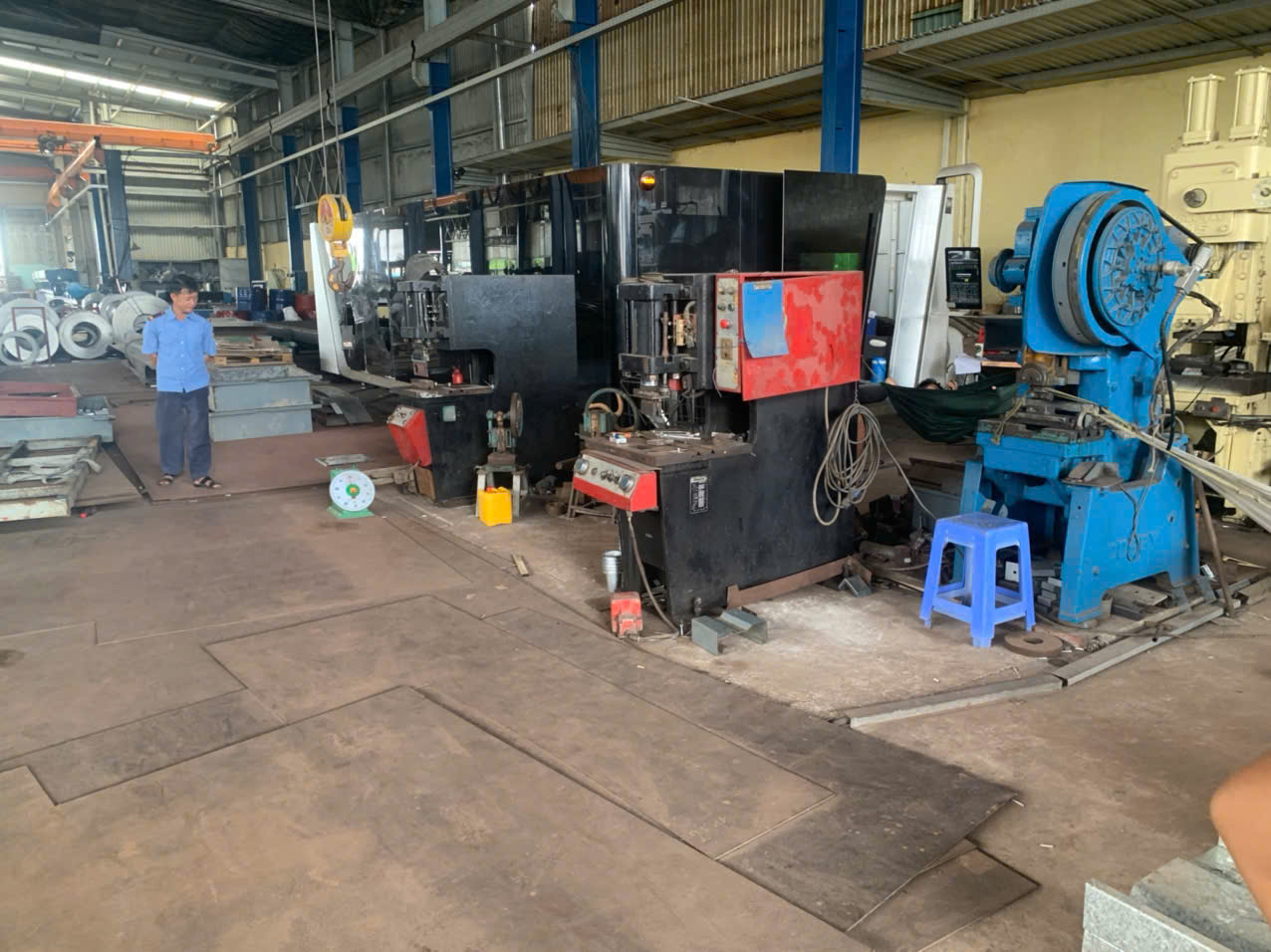
Most buyers over-focus on overall length and width. That is a mistake. A stamped clip can be perfectly "in size" overall and still fail because a punched slot shifted relative to a bend. The real risk sits in the dimensions that interact with tooling: holes, slots, bends, radii, and edge distances.
Start with function, not the print
Before you send an RFQ, trace how the part is used. Which holes take fasteners? Which flange touches a mating surface? Which edge carries load? Those features get tight control. Everything else can carry general tolerances, and your supplier will thank you with a better price.
Separate feature types
Different stamping processes hold different accuracy. Punched holes are very repeatable. Bent flanges are less so, because springback 1 varies with material lots. Drawn or stretched features vary most. So one tolerance rule should never apply to every feature.
| Dimension type | Typical criticality | Why it matters |
|---|---|---|
| Hole diameter and true position 2 | High | Fastener alignment, mating parts |
| Bend angle and radius | High | Assembly fit, springback 3 risk |
| Hole-to-bend distance | High | Forming can shift hole location |
| Edge distance from holes | Medium-High | Distortion and tearing risk |
| Overall length and width | Medium | Rarely the true failure point |
| Cosmetic surfaces, non-mating edges | Low | Function unaffected |
Mark your criticals clearly
When we prepare a PPAP 4 package for a US client, we ask them to flag critical dimensions with symbols or a numbered ballooned drawing. This tells the supplier where to focus process control, and it tells the inspector exactly what to measure on every lot. Datums matter here too. Reference datums that a CMM or gauge can actually touch, not a flexible formed lip that moves when you clamp it.
Which tolerance ranges should I specify to avoid costly rework with my supplier?
One trade-off we weigh on every custom-parts project: tighter tolerances buy security on paper but pay for it in tooling cost, slower press speeds, higher scrap, and more inspection time. Loose tolerances risk fit problems. The answer is matching each tolerance to real need.
Specify ±0.125 mm to ±0.25 mm for critical punched features, ±0.5 mm to ±1.5 mm for general dimensions, and about ±1 degree for bend angles. Use profile tolerances for complex formed contours instead of stacked linear dimensions, and tighten only critical-to-function features.

Tolerances are not free. The most common mistake I see on incoming drawings is a blanket tight tolerance applied to every dimension, often copied from a machined-part template. Stamping is not machining. A progressive die holds punched features very well, but bent and formed features move with material lot variation, tool wear, and press settings.
Practical tolerance bands by feature
| Feature | Achievable range | Notes |
|---|---|---|
| Punched hole diameter | ±0.05 to ±0.125 mm | Very repeatable within one die |
| Hole true position (same station) | ±0.1 mm | Punched together = highly stable |
| Hole position across a bend | ±0.25 to ±0.5 mm | Springback adds variation |
| Bend angle | ±1 degree | Tighter needs coining or restrike |
| Flange length after bend | ±0.25 to ±0.5 mm | Depends on bend allowance accuracy |
| Overall profile (formed) | ±0.5 to ±1.5 mm | Prefer profile tolerance callouts |
| Flatness | 0.1–0.3 mm per 100 mm | Specify only where stacking or sealing |
Why over-tolerancing costs you twice
First, the quote goes up. A supplier who sees ±0.05 mm on a bent flange either prices in restrike operations and 100% inspection, or quotes high to cover risk. Second, rework and disputes go up. If the tolerance cannot be held at production speed, you get borderline parts, deviation requests, and delayed shipments. On our projects, we run a DFM review before tooling kicks off and push back on any tolerance the process cannot hold repeatably. That single conversation prevents most rework later.
Also specify what many buyers forget: burr height and burr direction. Burrs matter for manual handling, electrical parts, and sealing surfaces. State a maximum burr height, typically 10% of material thickness, and note which side the burr may face.
What material thickness and springback factors affect my stamping part dimensions?
During a stainless clip project we managed from our Vietnam side, the first-article bends came in two degrees open. Same die, same press, different material lot. That is springback, and it is the reason material data belongs in every stamping RFQ.
Material thickness sets nearly every design limit: minimum hole size, slot width, edge distance, and bend radius are all multiples of thickness. Springback, driven by material strength and grade, opens bend angles after forming, so dies must overbend or coin to hit final dimensions.

Thickness is the base reference in stamping. Almost every design rule scales from it. Change the gauge, and the rules change with it. Change the material grade, and springback behavior changes even if the geometry stays identical.
Thickness-based design rules to check
| Feature | Rule of thumb | Material note |
|---|---|---|
| Minimum hole diameter | 1.2× thickness (ductile steel) | 2× thickness for stainless and high-strength alloys |
| General hole/slot minimum | 1.5× thickness | Common design-guide baseline |
| Slot or tab width | ≥1.5× thickness | Prevents punch distortion and breakage |
| Hole-to-edge distance | ≥2× thickness | More near bends or large holes |
| Hole-to-hole spacing | ≥1.5× thickness | Prevents tearing between perforations |
| Minimum inside bend radius | 0.5× thickness (mild steel) | ~1× thickness for stainless |
| Hole-to-bend distance | ≥2× thickness + bend radius | Or the hole distorts during forming |
Springback changes by alloy
Springback is elastic recovery after the punch lifts. Higher-strength materials store more elastic energy, so they spring back more. Mild steel is forgiving. High-strength steel, aluminum, and copper alloys each need different die compensation, usually overbending past the target angle or coining the bend line. A supplier who understands your specific grade will compensate the die correctly the first time. A supplier who does not will chase the angle through trial and error, and your delivery date pays the price.
Also remember thickness tolerance itself. Sheet stock arrives with gauge variation from the mill. On thin parts, that variation flows straight into flange heights, form heights, and hole quality. If gauge matters for your assembly, specify the thickness tolerance on the drawing, not just the nominal.
One more factor: grain direction 5. Bending parallel to the rolling grain raises cracking risk on tight radii. We flag grain direction during DFM review whenever a bend radius sits near the material limit.
How do I verify a supplier's dimensional accuracy through PPAP and inspection reports?
A US purchasing manager once told me his previous supplier sent beautiful sample parts, then shipped production lots that would not assemble. The tooling had shifted between soft prototype dies and hardened production dies, and nobody re-verified. That gap is exactly what PPAP exists to close.
Verify dimensional accuracy by requiring a PPAP package with a ballooned drawing, full-dimension first-article report, capability studies (Cpk ≥ 1.33) on critical dimensions, gauge R&R data, and measurement traceability to your datums. Then confirm ongoing lots with sampled in-process and final inspection reports.

PPAP is not paperwork for its own sake. It is proof that the production process, not just one hand-picked sample, can hold your dimensions. When we run PPAP for clients sourcing from Vietnam or elsewhere in Asia, we treat it as a gate: no full production release until the package passes.
What a solid dimensional verification package includes
- A ballooned drawing where every dimension has a number matching the inspection report.
- A full first-article inspection covering all dimensions, measured on parts from production tooling at production speed, not slow-run samples.
- Capability studies on the critical-to-function dimensions. A Cpk 6 of 1.33 or higher shows the process holds the tolerance process capability 7 with margin, not by luck.
- Gauge R&R showing the measurement system itself is reliable. A CMM report means little if the fixturing distorts a flexible formed part.
- Datum consistency. Check that the inspection setup uses the same datums as the drawing, and that datums did not change when tooling moved from prototype to hardened production dies.
- Tolerance stack-up analysis for progressive-die parts with many features, because individual station tolerances can compound across the strip.
What to watch on ongoing production
First articles prove capability once. Production drift comes later, from punch wear, die shoe flex, and strip-feed variation. Ask how often the supplier measures critical dimensions during a run, and ask to see real in-process data, not just a final certificate. On our contract manufacturing projects we combine in-process checks with a final inspection before shipment, because catching a drifting bend angle mid-run is cheap. Catching it in your warehouse in the US is not. Payment terms help here too: when a supplier relationship includes credit terms and repeat business, both sides have skin in the game to get it right the first time.
Conclusion
Buying stamping parts well means controlling the right dimensional parameters, not every dimension. I have watched loose specs cause returns and tight specs inflate quotes. The fix is the same: flag critical features, match tolerances to the process, account for thickness and springback, and verify through PPAP. Get those four steps right, and your stamped parts fit the first time, every lot.
Frequently Asked Questions
How do I identify critical dimensions on my stamping part drawings before quoting?
A few years back, our Vietnam office reviewed a bracket drawing with 47 toleranced dimensions. After a call with the client's engineer, only six actually affected assembly. That review cut tooling cost by a third.
Which tolerance ranges should I specify to avoid costly rework with my supplier?
One trade-off we weigh on every custom-parts project: tighter tolerances buy security on paper but pay for it in tooling cost, slower press speeds, higher scrap, and more inspection time. Loose tolerances risk fit problems. The answer is matching each tolerance to real need.
What material thickness and springback factors affect my stamping part dimensions?
During a stainless clip project we managed from our Vietnam side, the first-article bends came in two degrees open. Same die, same press, different material lot. That is springback, and it is the reason material data belongs in every stamping RFQ.
Footnotes
1. Background concept on elastic recovery after forming, central to bend angle control. ↩︎
2. Explains true position concept used for hole location tolerancing in stamped parts. ↩︎
3. Explains the metal-forming phenomenon affecting bend angle accuracy discussed in this section. ↩︎
4. Background on the Production Part Approval Process standard referenced throughout this section. ↩︎
5. Explains rolling grain orientation referenced for cracking risk on tight bend radii. ↩︎
6. Defines the process capability index metric used to judge dimensional control. ↩︎
7. Background on Cpk statistic used to evaluate supplier dimensional capability. ↩︎