
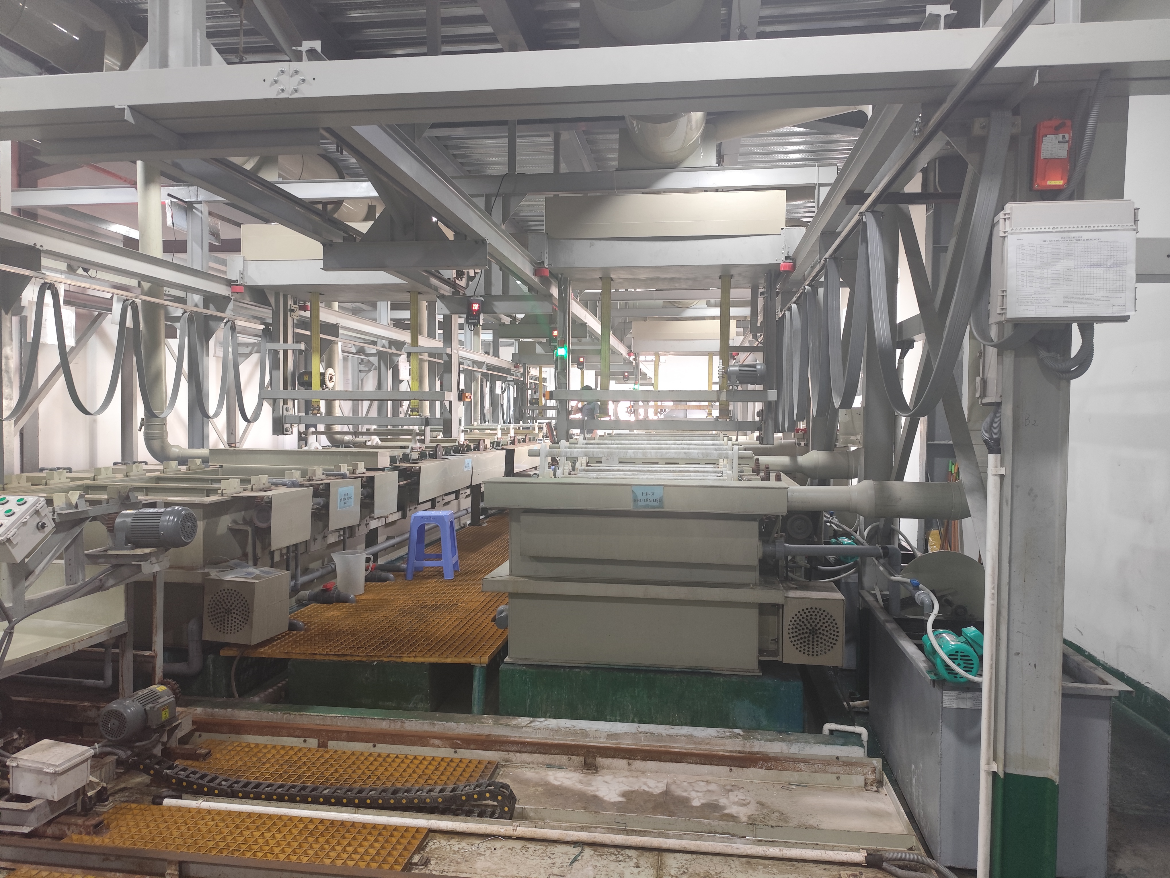
I once received a batch of mounting brackets that looked perfect — until they wouldn’t fit into the housing First Article Inspection 1. The dimensional tolerances 2 on bends were off by just 0.5 mm. That tiny gap cost weeks of rework. It’s a problem I see constantly when sourcing sheet metal fabrication 3 for U.S. clients from Asian suppliers. The frustration compounds when nobody catches it until final assembly. The good news? A clear understanding of tolerances and finishes prevents this entirely.
Dimensional tolerances and surface finishes are the two pillars of sheet metal fabrication quality. Key tolerances range from ±0.005 inches for flat features to ±0.030 inches for features across multiple bends, while finishes like powder coating add ±0.003 inches that must be factored into design specs to ensure proper fit and function.
This guide breaks down the exact tolerances and finishes you need to specify, why they matter for cost and quality, and how to communicate them clearly to your offshore fabrication partner. Let’s walk through each critical area step by step.
How do I define the right dimensional tolerances to ensure my parts fit perfectly every time?
A lesson I learned early in our supply chain work: a client sent drawings with ±0.005 inches on every dimension — including features across four bends. The supplier quoted three times the expected price. The truth is, not every feature needs the tightest tolerance.
Define dimensional tolerances by feature type: use ±0.005 inches for flat features like edge-to-edge and hole-to-hole, ±0.010 inches for single bends, and ±0.030 inches for features across multiple bends. Apply ISO 2768-mK as the general default and tighten only critical dimensions that affect fit or function.

Why One-Size-Fits-All Tolerancing Fails
Sheet metal is not CNC machining. Every bend introduces variation. Every weld adds distortion. When you apply a blanket tight tolerance to an entire drawing, you force the supplier into unnecessary inspection, slower production, and higher reject rates. The result? Inflated costs and delayed delivery.
The smarter approach is to start loose and tighten only where it matters. This is what ISO 2768 4 was designed for. The "Medium" class (M) covers most general fabrication needs. You apply it as a blanket standard, then call out specific critical features with tighter tolerances.
Feature-by-Feature Tolerance Breakdown
Here is how standard precision and tolerance ranges break down by geometric relationship:
| Feature Relationship | Typical Tolerance (inches) | Typical Tolerance (mm) |
|---|---|---|
| Edge-to-Edge (single surface) | ±0.005 | ±0.13 |
| Edge-to-Hole (single surface) | ±0.005 | ±0.13 |
| Hole-to-Hole (single surface) | ±0.005 | ±0.13 |
| Hole-to-Hardware | ±0.010 | ±0.25 |
| Edge-to-Hardware | ±0.010 | ±0.25 |
| Hardware-to-Hardware | ±0.015 | ±0.38 |
| Single Bend-to-Edge | ±0.010 | ±0.25 |
| Bend-to-Bend | ±0.015 to ±0.030 | ±0.38 to ±0.76 |
| Holes Across 2 Bends | ±0.030 | ±0.76 |
| Holes Across 4 Bends | ±0.030 or higher | ±0.76+ |
This table is the single most important reference when marking up your drawings. If you dimension a hole position across four bends at ±0.005 inches, you are asking for something physically difficult to achieve. The material springs back. The tooling has limits. The angular tolerance on each bend compounds.
The Role of Material Properties
Material type directly affects what the shop floor can hold. Stainless steel 304, for example, typically holds ±0.005 to ±0.015 inches depending on the feature. Aluminum is more forgiving for flat cuts but can spring back more during bending. Grain direction matters too — bending against the grain increases the risk of cracking and dimensional drift.
Laser cutting tolerance is the tightest you will get in primary fabrication. For flat parts up to 1000 mm, expect ±0.1 mm. But once that flat part hits the press brake, flatness tolerance and angular tolerance become the dominant concerns.
The Tolerance Stack-Up Problem
When multiple bends are involved, tolerances stack. A part with four bends can accumulate error from each bend. This is tolerance stack-up 5 in action. If each bend introduces ±0.010 inches of variation, four bends could theoretically shift a hole position by ±0.040 inches. That is why holes across multiple bends carry wider tolerances.
I always advise our clients to avoid dimensioning critical features across multiple bends whenever possible. If the design allows, reference critical holes and hardware to a single datum surface. This reduces stack-up and makes inspection straightforward.
Which surface finishes should I choose to meet my specific durability and quality requirements?
One trade-off I weigh on nearly every project is whether to specify powder coating 6 or anodizing — and the answer always depends on the base material, the end-use environment, and the dimensional impact the finish will have on the part.
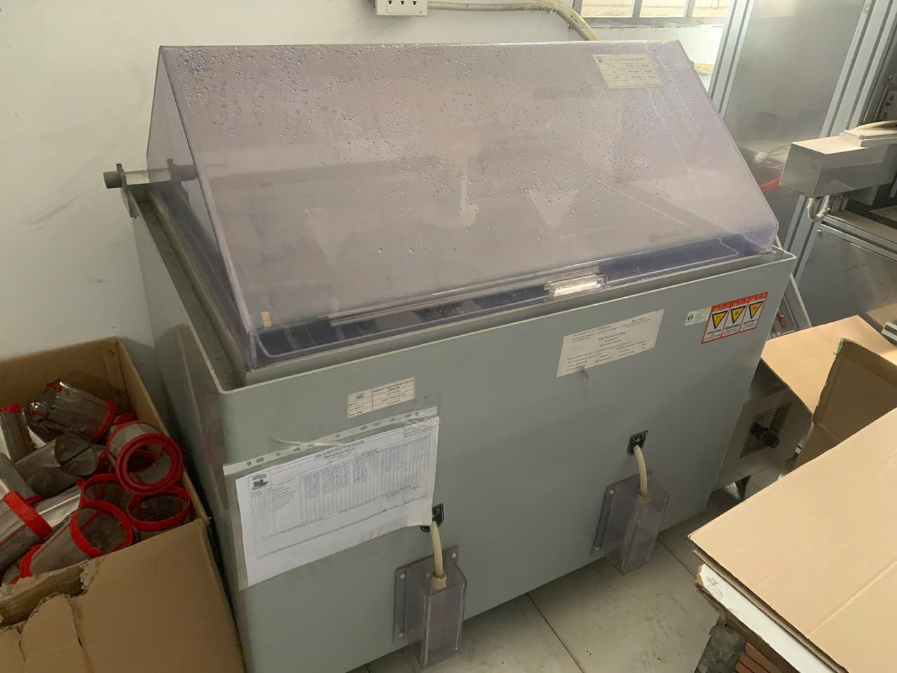
Choose powder coating for steel parts requiring corrosion resistance and color consistency, anodizing for aluminum parts needing a thin, hard protective layer, and a brushed finish or passivation for stainless steel. Always account for finish thickness in your tolerance calculations — powder coating alone adds ±0.003 inches to part dimensions.
Matching Finish to Function
Surface finishes 7 do more than make parts look good. They protect against corrosion, improve wear resistance, and can affect electrical conductivity. The wrong finish choice leads to premature failure. The wrong finish thickness leads to assembly problems.
Here is a comparison of the most common finishes we source for our U.S. clients:
| Finish Type | Best For | Typical Thickness | Dimensional Impact | Durability |
|---|---|---|---|---|
| Powder Coating | Steel, aluminum (color, corrosion) | 0.002–0.005 in | ±0.003 in allowance needed | High |
| Anodizing 8 (Type II) | Aluminum (corrosion, aesthetics) | 0.0002–0.001 in | Minimal | Medium-High |
| Passivation | Stainless steel (corrosion) | Negligible | None | Medium |
| Electroplating (Zinc) | Steel (corrosion protection) | 0.0002–0.001 in | Minimal | Medium |
| Brushed Finish | Stainless steel, aluminum (aesthetics) | N/A (surface texture) | None | Low-Medium |
| Bead Blasting | All metals (uniform matte look) | N/A (surface texture) | None | Low |
| Galvanizing | Steel (heavy corrosion environments) | 0.003–0.006 in | Significant | Very High |
Powder Coating: The Hidden Dimension Trap
Powder coating is by far the most common finish for carbon steel sheet metal parts. It provides excellent corrosion resistance, a wide range of colors, and good scratch resistance. But here is the problem I see repeatedly: designers forget to account for the coating thickness.
A powder coat layer typically adds 0.002 to 0.005 inches per side. If a part slides into a slot or mates with a tight housing, that extra material can prevent assembly. Our quality control team always checks whether the drawing accounts for post-finish dimensions. If it does not, we flag it before production begins.
Ra Value and Machined Surfaces
For CNC machined features on sheet metal parts — like tapped holes or milled surfaces — the Ra value defines surface roughness. A standard "As Milled" finish gives you about Ra 3.2 µm (125 µin). If your application needs a smoother contact surface, specify Ra 1.6 µm or Ra 0.8 µm, but expect added cost from secondary polishing.
Environmental Considerations
An emerging factor in finish selection is environmental impact. Powder coating generates less waste than wet painting. Passivation uses mild acids rather than heavy chemicals. More of our clients now ask about eco-friendly alternatives, and we help them find suppliers that meet both quality and sustainability goals.
How can I ensure my offshore supplier accurately follows the critical tolerances on my drawings?
A buyer I work with in the Midwest told me about a supplier who built an entire run of brackets to the wrong thickness tolerance — because the drawing note referenced ASME Y14.5, but the shop floor was working from ISO 2768. Nobody caught the discrepancy until parts arrived in the U.S.
Ensure your offshore supplier follows critical tolerances by providing fully dimensioned drawings with explicit tolerance callouts, referencing a single standard like ISO 2768 or ASME Y14.5, conducting a First Article Inspection (FAI) with detailed measurement reports, and establishing a PPAP process that locks in process controls before mass production begins.

The Communication Gap
The root cause of most tolerance failures is not bad equipment or poor skill. It is miscommunication. When we manage projects for U.S. clients sourcing from Vietnam or other Asian suppliers, the first thing we do is review every drawing for ambiguity. A note that says "standard tolerances apply" means different things in different shops. You must be explicit.
Here is a practical checklist:
- State the governing standard clearly. Write "General tolerances per ISO 2768-mK" in the title block. Do not assume the supplier will guess.
- Call out critical dimensions individually. Use GD&T symbols or direct tolerance callouts on every feature that affects fit, form, or function.
- Define inspection criteria. Specify which dimensions get measured, how many samples, and what instruments to use.
- Request a First Article Inspection Report (FAIR). This is a full dimensional report on the first production piece. It catches problems before the full run.
The PPAP Approach
For our medium-to-high quality projects, we use a Production Part Approval Process (PPAP). PPAP process 9 This is standard in automotive but underused in general sheet metal. The PPAP documents the process — from material certification to press brake settings to inspection results — so every run repeats the same quality. It is the best tool I know for ensuring "right first time" results.
Bridging Standards Between Regions
When you source from Asia, your supplier may default to ISO standards while your engineering team uses ASME Y14.5. Both are valid, but they are not interchangeable. ISO 2768 defines general tolerance classes (Fine, Medium, Coarse, Very Coarse). ASME Y14.5 uses Geometric Dimensioning and Tolerancing with specific datum references and feature control frames.
| Aspect | ISO 2768 | ASME Y14.5 |
|---|---|---|
| Approach | General tolerance classes | Feature-specific GD&T |
| Common Class | Medium (M) | Not class-based |
| Flatness / Angularity | Defined by tolerance class | Defined per feature |
| Best For | General fabrication, sheet metal | Complex assemblies, aerospace |
| Adoption | Asia, Europe | North America |
The solution? Pick one standard and state it clearly on every drawing. If your supplier works in ISO and you work in ASME, include a conversion note or a dual-standard tolerance table. Our engineering team in Vietnam regularly bridges this gap for clients.
Digital Tools for Verification
Some of our more advanced projects use digital measurement reports where the supplier scans parts with a CMM (Coordinate Measuring Machine) and overlays results on the CAD model. This catches deviations in flatness tolerance, hole position, and angular tolerance that hand measurements might miss. It is not cheap, but for critical parts it pays for itself in avoided rework. Learn more about how to evaluate quality inspection equipment and CMMs when selecting a fabrication partner.
What steps can I take to prevent quality issues caused by incorrect finish or tolerance specs?
Early in our work with a U.S. distributor, we discovered that their supplier had been applying a brushed finish in the wrong direction — across the grain instead of with it. The parts looked acceptable individually, but side by side in the final assembly, the inconsistency was obvious. Prevention starts long before production.
Prevent quality issues by creating a comprehensive specification document that pairs each feature with its tolerance and finish requirement, conducting pre-production samples with full inspection, building a quality control plan that covers both dimensional and cosmetic criteria, and maintaining open communication with your supplier at every project milestone.

Build a Sourcing Specification Document
The most effective tool I have seen for preventing quality problems is a single-page spec document that lives alongside the drawing. It lists:
- Critical dimensions with their exact tolerances
- Surface finish requirements with Ra value or finish type
- Finish thickness allowance (e.g., +0.003 inches for powder coating)
- Inspection points and acceptance criteria
- Packaging requirements to protect finished surfaces
This document eliminates guesswork. When our team in Vietnam conducts supplier audits, we check whether the shop floor has this document posted — not buried in an email.
The "Loosest Acceptable" Rule
One principle that saves our clients money and headaches: always start with the loosest acceptable tolerance. Apply ISO 2768-mK as your blanket standard. Then tighten only the features that matter — mounting holes, mating surfaces, hardware locations. This approach can reduce fabrication cost by 20–30% compared to blanket tight tolerancing.
Here is a decision framework:
| Question | If Yes | If No |
|---|---|---|
| Does this feature mate with another part? | Tighten tolerance | Use general tolerance |
| Does this surface face the customer? | Specify finish and Ra value | Leave as-fabricated |
| Does the part receive powder coating? | Add ±0.003 in to dimensions | No adjustment needed |
| Are holes located across multiple bends? | Widen tolerance to ±0.030 in | Standard ±0.005 in applies |
| Is angular tolerance critical for assembly? | Specify ±0.5° or tighter | ISO 2768-M default (±1.0°) |
Pre-Production Samples Are Non-Negotiable
Never skip the sample phase. A pre-production sample — even just 3 to 5 pieces — lets you verify dimensions, finish quality, and material properties before committing to a full run. Our process requires the supplier to submit samples with a measurement report. We compare every critical dimension against the drawing. If anything is out of spec, we work with the supplier to adjust tooling or process settings before mass production.
Ongoing Process Control
Quality is not a one-time check. Material lots change. Tooling wears. Operators rotate. Ongoing process control means periodic inspections during production, not just at the end. Our quality control team conducts in-process checks at defined intervals — typically every 50 to 100 pieces for sheet metal runs. We measure the same critical features each time and track trends. If a dimension starts drifting toward the tolerance limit, we intervene before it goes out of spec.
Laser cutting tolerance stays consistent because the machine is CNC-controlled. But bending, welding, and finishing are more operator-dependent. That is where process control matters most.
Conclusion
Getting dimensional tolerances and surface finishes right is the difference between parts that fit and parts that fail. Specify tolerances by feature type, account for finish thickness, communicate clearly with your supplier using a single standard, and never skip pre-production samples. These steps protect your budget, your timeline, and your reputation.
Frequently Asked Questions
How do I define the right dimensional tolerances to ensure my parts fit perfectly every time?
A lesson I learned early in our supply chain work: a client sent drawings with ±0.005 inches on every dimension — including features across four bends. The supplier quoted three times the expected price. The truth is, not every feature needs the tightest tolerance.
Which surface finishes should I choose to meet my specific durability and quality requirements?
One trade-off I weigh on nearly every project is whether to specify powder coating 6 or anodizing — and the answer always depends on the base material, the end-use environment, and the dimensional impact the finish will have on the part.
How can I ensure my offshore supplier accurately follows the critical tolerances on my drawings?
A buyer I work with in the Midwest told me about a supplier who built an entire run of brackets to the wrong thickness tolerance — because the drawing note referenced ASME Y14.5, but the shop floor was working from ISO 2768. Nobody caught the discrepancy until parts arrived in the U.S.
Footnotes
1. Provides a comprehensive and authoritative overview of First Article Inspection. ↩︎
2. Provides a comprehensive definition and explanation of engineering and dimensional tolerances in manufacturing. ↩︎
3. Provides a comprehensive overview of sheet metal fabrication. ↩︎
4. Provides a clear explanation of ISO 2768, its parts, tolerance classes, and application in manufacturing. ↩︎
5. Explains tolerance stack-up analysis, its purpose in mechanical engineering, and methods for calculation. ↩︎
6. Defines powder coating as a dry finishing process, its application, curing, and durability compared to liquid paint. ↩︎
7. Explains surface finish, its importance in engineering, and various methods and parameters. ↩︎
8. Explains anodizing as an electrochemical process that enhances durability, corrosion resistance, and aesthetics of metal surfaces. ↩︎
9. Defines PPAP as a standardized framework to ensure a supplier’s manufacturing process consistently meets customer requirements. ↩︎