

Flatness and evenness standards for stamping parts confuse many buyers we work with. A bracket looks flat on the drawing, then rocks on the assembly table. That gap costs money.
Flatness and evenness standards for stamping parts come from ASME Y14.5 GD&T flatness callouts, ISO 2768-2 general tolerances, and ASTM sheet standards. Typical values are 0.005 inch T.I.R. for parts under 1 inch, scaling up with part size and thickness.
There is no single universal standard. The real answer is a stack of references. Let me walk you through how each one works, and how we apply them on real stamping projects.
How Do I Measure Flatness and Evenness on Stamping Parts Accurately?
A few years back, our Vietnam inspection team rejected a batch of galvanized mounting clips that a supplier swore were flat. Their check used a ruler and eyeballs. Ours used a granite plate and dial indicators. The difference mattered.
Measure flatness by placing the part on a granite surface plate and checking the gap with feeler gauges or a dial indicator. For tight tolerances under 0.1 mm, use a CMM or laser scanner to map the full surface between two parallel reference planes.

Flatness only means something if everyone measures it the same way. In GD&T terms, flatness defines a zone between two parallel planes. Every point on the controlled surface must sit between them. It is a form control. It does not reference a datum, and it does not control orientation to other features unless you add separate callouts.
Common Measurement Methods
Different tolerance levels demand different tools. Here is how we match method to requirement on our inspection benches.
| Method | Typical Resolution | Best For | Limitation |
|---|---|---|---|
| Straightedge + feeler gauge | 0.05 mm | Shop-floor checks, loose tolerances | Only samples a few lines |
| Granite plate + dial indicator | 0.01 mm | General stamped brackets | Operator technique matters |
| CMM (coordinate measuring machine 1) | 0.002–0.005 mm | Precision parts, PPAP reports | Slow, point-based sampling |
| Laser / optical scanning | 0.005–0.02 mm | Full surface maps, thin panels | Higher equipment cost |
Watch for Measurement Traps
Three mistakes we see suppliers make constantly. First, they clamp the part flat before measuring. That hides the true free-state condition. Unless the drawing allows restrained measurement, check the part unclamped. Second, they measure only the corners. A part can touch at four corners and still bow badly in the middle. Third, they confuse T.I.R. (total indicator reading) with per-point deviation. T.I.R. captures the full range between the highest and lowest points, which is what most stamping tolerance tables mean.
When we run final inspection for U.S. clients, we document the method on the report. A flatness number without a stated method is only half an answer, and it invites disputes at incoming inspection.
What Causes Flatness Deviations in My Stamping Parts?
One trade-off we weigh on nearly every bracket project is hole placement versus distortion. A client once insisted on slots close to a bend line. The parts came off the die twisted. Moving the slots 1.5 times material thickness away fixed it.
Flatness deviations come from residual stresses released during blanking and piercing, springback after bending, coil set and crossbow in the raw material, uneven blank holder pressure, worn die clearance, and holes placed too close to edges or bends.
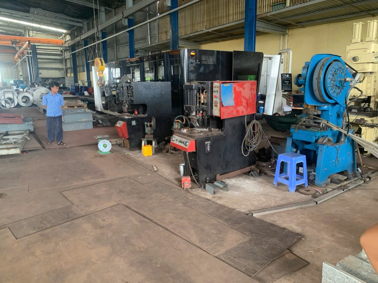
A flat sheet does not guarantee a flat part. That is the point most buyers miss. Stamping introduces new stresses at every station. Understanding where the distortion starts helps you fix it at the source instead of arguing about it at inspection.
Material-Driven Causes
The coil arrives with its own problems. Coil set is the curl left from being wound. Crossbow is a curve across the width. If the supplier skips proper leveling before blanking, that stress stays inside the part and releases later, often after trimming. Thinner gauges suffer more. A 0.5 mm stainless clip warps far more easily than a 2 mm steel bracket, because thin material has less stiffness to resist locked-in stress.
Grain direction matters too. Bends made perpendicular to the rolling direction 3 spring back more predictably than bends made parallel to it. Good shops orient the strip layout with this in mind.
Process-Driven Causes
Here are the main process factors, ranked roughly by how often we see them cause rejections:
- Piercing near edges or bends. Punched holes thin and stress the surrounding metal. Too close together, and the web between them distorts.
- Springback. Every bend relaxes slightly after the punch retracts. High-strength steels spring back more.
- Die clearance wear. As punches dull, cutting forces rise and drag more stress into the part.
- Uneven blank holder pressure. Inconsistent hold-down lets material flow unevenly during forming.
- Progressive die sequencing. A poor station order can lock warp into the strip before final cutoff. This one is often overlooked, even by experienced toolmakers.
Secondary operations can recover flatness. Roller leveling, coining, restrike stations, and stress-relief annealing 4 all help. But each one adds cost, so prevention through tooling design is always cheaper.
How Can I Ensure My Supplier Meets Flatness Tolerances Consistently?
A purchasing manager in the U.S. once told me his biggest frustration was suppliers who passed the first article, then drifted out of spec by shipment three. We hear that story often, and it shaped how our team audits stamping suppliers across Vietnam and Taiwan.
Ensure consistent flatness by requiring a PPAP with capability data on the flatness dimension, defining the measurement method in the contract, auditing the supplier's die maintenance and leveling equipment, and adding flatness to the final inspection sampling plan for every shipment.

First articles prove capability once. Consistency proves it every time. The gap between the two is where most quality escapes happen, and closing it takes process discipline, not luck.
Build Flatness Into the Quality Process
We treat flatness like any critical dimension in a control plan. That means it needs four things: a clear spec, an agreed measurement method, a capability study, and ongoing monitoring. When we run PPAP 5 for clients, we ask the supplier to show a Cpk on the flatness characteristic, not just a single passing measurement. A part measuring at 80% of tolerance on day one will fail as the die wears.
Die maintenance is the hidden variable. Sharp punches cut cleanly with low stress. Dull punches drag and distort. Ask your supplier for their punch regrind schedule. If they cannot show one, flatness will drift.
A Practical Supplier Checklist
| Checkpoint | What to Ask For | Red Flag |
|---|---|---|
| Measurement agreement | Written method: free state, T.I.R., tool used | "We check it visually" |
| PPAP / first article | Capability data on flatness, not just one reading | Single-point pass at tolerance limit |
| Die maintenance | Punch regrind and clearance inspection schedule | No maintenance records |
| Material control | Mill certs plus leveling before blanking | Coil fed straight to the die |
| Ongoing inspection | Flatness in the sampling plan per lot | Flatness checked only at FAI |
| Corrective capacity | Access to leveling or restrike operations | No recovery plan for warped lots |
Our Vietnam team performs final inspection before containers load. We measure flatness on sampled parts against the agreed method and attach photos and readings to the report. That step alone has prevented several disputed shipments, because both sides see the same numbers before the goods leave port.
What Flatness Standards Should I Specify in My Stamping Drawings?
The most expensive drawing mistake I have reviewed was a blanket 0.05 mm flatness note applied to every surface of a simple shelf bracket. The client only needed it on one mounting face. The quote came back triple the target price until our engineers helped rewrite the callout.
Specify GD&T flatness per ASME Y14.5 on functional surfaces only, reference ISO 2768-2 class K or L for everything else, and follow size-based guidance: about 0.005 inch T.I.R. under 1 inch, 0.005 inch per inch up to 4 inches, looser beyond.

Good drawings separate what matters from what does not. A mounting face that must seal or sit flush deserves a tight callout. A cosmetic flange does not. Over-specifying is the fastest way to inflate stamping quotes.
Choose the Right Standard for Each Purpose
Each standard covers a different question. Use them together, not interchangeably.
| Standard | What It Governs | When to Use It |
|---|---|---|
| ASME Y14.5 | GD&T flatness callout on the drawing | Critical mating, sealing, or mounting surfaces |
| ISO 2768-2 6 | Default flatness/straightness when no callout exists | General tolerance note for noncritical surfaces |
| ASTM A480 7 and sheet specs | Mill flatness of incoming flat products | Material purchase specs, not finished parts |
| Supplier design guides | What shops can realistically hold | Sanity-checking your tolerance before quoting |
| OEM standards | Customer-specific acceptance criteria | Automotive and other regulated programs |
Use Size-Based Tolerance Progressions
Common shop practice scales flatness with part size. Guidance published by established stamping houses follows this pattern: roughly 0.005 inch T.I.R. for surfaces up to 1 inch, 0.005 inch per inch for surfaces from 1 to 4 inches, and 0.020 inch plus 0.004 inch per additional inch beyond that. Treat these as manufacturability baselines, not laws. Precision electronics stampings can hold around ±0.1 mm or tighter with the right tooling, while large automotive brackets may accept 0.5 to 1 mm per 100 mm.
Two more drafting tips from our project files. First, state whether measurement is in the free state or restrained. Thin parts change shape under their own clamping. Second, if the surface must also be parallel to another face, add a parallelism callout with a datum. Flatness alone will not control that relationship, and assuming it does is one of the most common drawing errors we correct during co-development reviews.
Conclusion
Flatness and evenness standards for stamping parts are a stack: GD&T for callouts, ISO and ASTM for defaults, supplier capability for reality. Specify only what functions demand, then verify it consistently.
Frequently Asked Questions
How Do I Measure Flatness and Evenness on Stamping Parts Accurately?
A few years back, our Vietnam inspection team rejected a batch of galvanized mounting clips that a supplier swore were flat. Their check used a ruler and eyeballs. Ours used a granite plate and dial indicators. The difference mattered.
What Causes Flatness Deviations in My Stamping Parts?
One trade-off we weigh on nearly every bracket project is hole placement versus distortion. A client once insisted on slots close to a bend line. The parts came off the die twisted. Moving the slots 1.5 times material thickness away fixed it.
How Can I Ensure My Supplier Meets Flatness Tolerances Consistently?
A purchasing manager in the U.S. once told me his biggest frustration was suppliers who passed the first article, then drifted out of spec by shipment three. We hear that story often, and it shaped how our team audits stamping suppliers across Vietnam and Taiwan.
Footnotes
1. Background on CMM technology used for precise flatness measurement of stamped parts. ↩︎
2. Official ASME standard governing the GD&T flatness callouts discussed in the article. ↩︎
3. Background on the rolling process affecting grain direction and springback in sheet metal. ↩︎
4. Explains the annealing process used to relieve residual stress causing flatness deviations. ↩︎
5. AIAG official source explaining the PPAP framework suppliers use to prove flatness capability. ↩︎
6. ISO publishes the general tolerance standard cited for noncritical flatness values. ↩︎
7. ASTM publishes mill flatness specifications for incoming flat stainless products mentioned in the table. ↩︎