
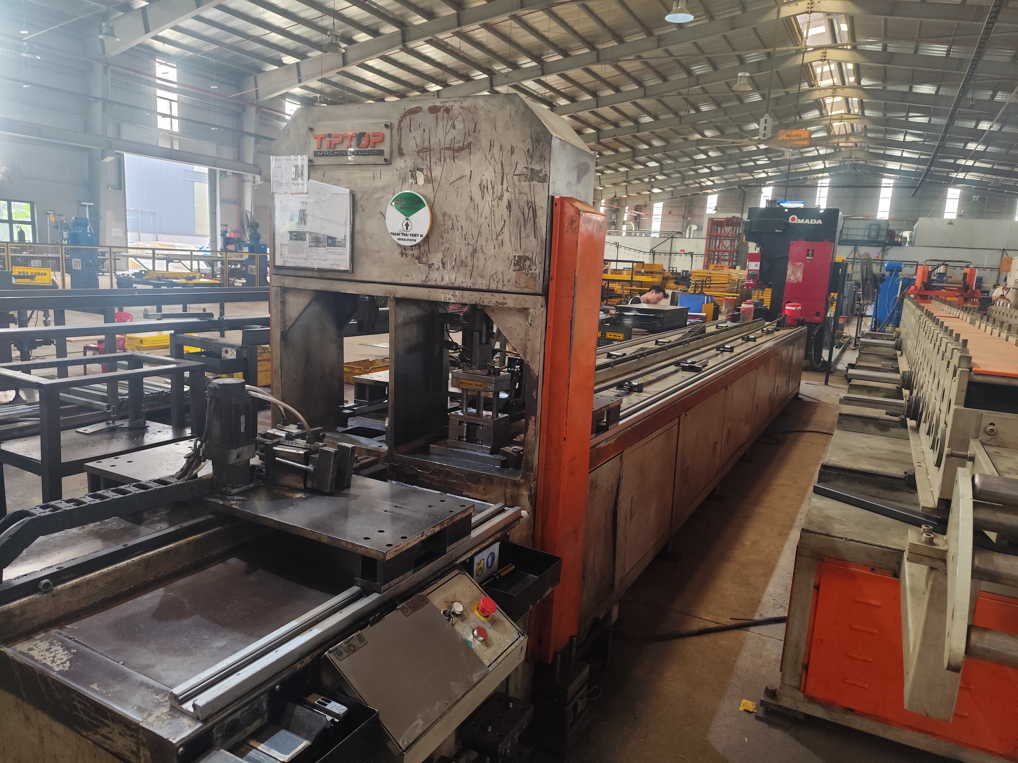
Last quarter, our quality team rejected an entire batch of stamped L-brackets because the supplier skipped proper dimensional checks — mounting holes were off by 0.3 mm, making assembly impossible.
Inspection tools that verify dimensional accuracy of stamping part samples include digital calipers, micrometers, height gauges, Coordinate Measuring Machines, optical comparators, 3D laser scanners, vision inspection systems, and go/no-go gauges — each selected based on tolerance requirements, part complexity, and production volume.
Choosing the wrong tool leads to missed defects, costly rework, and delayed shipments. Below, I walk through the inspection methods we rely on at every stage — from quick manual checks to advanced automated metrology — so you can match the right tool to your stamping project.
How do I choose the right measurement tools for verifying my stamping part tolerances?
A purchasing manager once asked me why we use four different tools on one bracket. The answer is simple: each dimension on a stamped part has a different tolerance band, and no single instrument covers them all efficiently.
Choose measurement tools by matching each tolerance band to the instrument's resolution: digital calipers and micrometers for general dimensions within ±0.01 mm, height gauges for formed features, and Coordinate Measuring Machines or vision inspection systems for critical tolerances below ±0.005 mm.

Start With the Drawing
Before picking up any tool, our engineers review the part drawing. They identify every dimension, its tolerance class, and whether Geometric Dimensioning and Tolerancing 1 call-outs apply. A flat bracket with ±0.1 mm on hole positions needs a different approach than an automotive mount requiring ±0.02 mm true position.
We classify dimensions into three tiers:
| Tier | Tolerance Range | Recommended Tools | Typical Use Case |
|---|---|---|---|
| General | ±0.1 mm or wider | Digital calipers, tape measures | Overall length, width, basic hole diameter |
| Standard | ±0.05 mm to ±0.01 mm | Digital micrometers, height gauges, pin gauges | Wall thickness, formed height, bore diameter |
| Critical | Tighter than ±0.01 mm | CMM, vision inspection systems, optical comparators | True position, profile tolerance, concentricity |
This tiered approach prevents over-inspection on non-critical features and under-inspection on the ones that matter.
Material Thickness Matters
Thin stamped sheets — say 0.5 mm stainless steel 2 — flex under probe pressure. When we source post base mounts or channel brackets from our Vietnam facility partners, we instruct inspectors to use non-contact optical methods 3 for any feature on material thinner than 1.0 mm. A tactile probe can push the surface down by several microns and give a false reading.
Environment and Volume
For prototype runs of 50 pieces, hand tools and a granite surface plate work fine. For production runs above 10,000 parts, we integrate go/no-go gauges and Statistical Process Control charts 4 to keep cycle times short. The tool choice is not just about precision — it is about throughput.
Cost vs. Capability
Digital micrometers cost under $200. A CMM can exceed $100,000. The question is not which tool is "best" but which tool gives you the accuracy you need at a cost you can justify. In our experience exporting to the US market, most custom bracket projects land in the standard tier — and a well-calibrated micrometer paired with a height gauge handles 70% of dimensions.
Can CMM inspection guarantee dimensional accuracy for my custom stamped components?
One lesson we learned early in our contract manufacturing work: a CMM report looks impressive, but it only guarantees what you program it to measure.
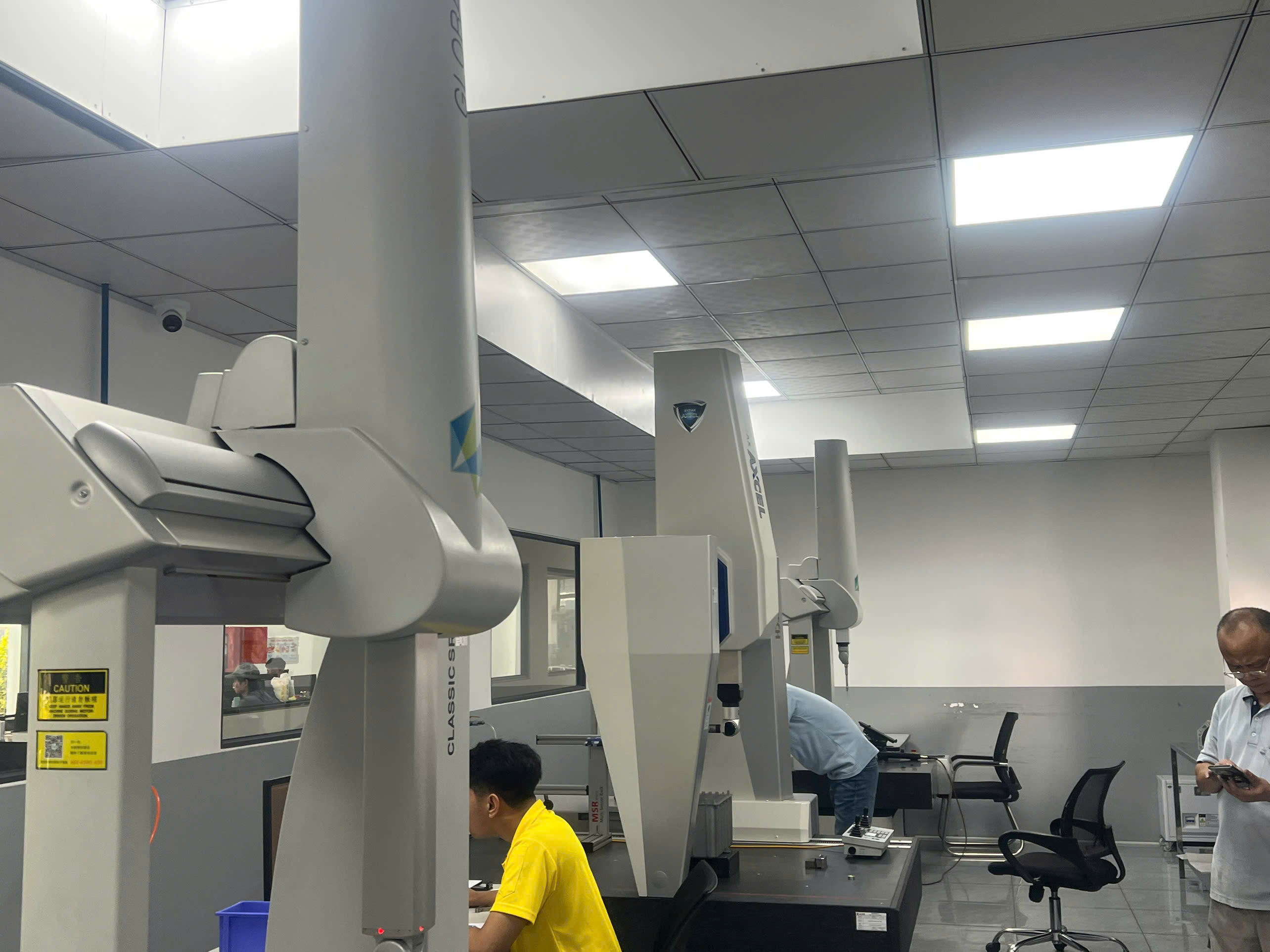
A Coordinate Measuring Machine provides micrometer-level 3D measurement of complex geometries, including flatness, perpendicularity, and true position — making it the gold standard for First Article Inspection — but it guarantees accuracy only when the probe strategy, fixturing, and measurement plan are properly defined.
How a CMM Works
A CMM uses a tactile probe — often a ruby-tipped stylus — mounted on a three-axis gantry. The probe touches specific points on the part surface. Software calculates distances, angles, and geometric relationships from these data points. Modern CMMs can also accept scanning probes that sweep along surfaces for continuous data collection.
For our stamped bracket projects, the CMM excels at verifying:
- True position of mounting holes relative to datum features
- Flatness of base plates
- Perpendicularity between a vertical channel and its base
- Profile of a stepped or notched edge
When CMM Falls Short
The CMM is not perfect for every stamping scenario. Here are the trade-offs we weigh:
| Advantage | Limitation |
|---|---|
| Micrometer-level 3D accuracy | Slow — each part can take 10–30 minutes |
| Full GD&T verification | Requires skilled programmer to create measurement routines |
| Repeatable and traceable results | Contact probe can deform thin sheet parts |
| Generates detailed inspection reports for PPAP | Expensive equipment and maintenance |
| Works with complex 3D geometries | Fixtures needed to hold parts consistently |
CMM in Our PPAP Workflow
When we manage Production Part Approval Process 5 documentation for US clients, the CMM report is the backbone of the dimensional results section. We measure all critical dimensions on 5 sample parts from the first production run. The data feeds directly into capability studies and Statistical Process Control charts. If Cpk values fall below 1.33, we flag the process for adjustment before mass production begins.
Fixturing: The Hidden Variable
A stamped bracket sitting loose on the CMM granite table will shift between measurements. We design custom fixtures — often simple aluminum nesting blocks — that locate the part on its datum surfaces. Without proper fixturing, even a $200,000 CMM produces unreliable data.
Contact vs. Non-Contact Considerations
For thick stamped parts like trailer hitch mounts or heavy post bases, the CMM probe force is negligible. But for thin flanges or delicate tabs, we switch to a non-contact laser probe or use a vision inspection system instead. The key is knowing your part's rigidity before choosing the measurement mode.
What role do go/no-go gauges play in my first article inspection process?
During a recent supplier audit in Vietnam, I watched an operator check 200 stamped brackets in under 15 minutes using a simple go/no-go fixture. No training manual. No software. Just insert, check, and sort.
Go/no-go gauges provide immediate pass/fail verification of critical features like hole diameters, slot widths, and bend angles during First Article Inspection and ongoing production — they are fast, require minimal training, and eliminate subjective measurement errors common with hand tools.
What Are Go/No-Go Gauges?
A go/no-go gauge is a fixed-limit gauge. The "go" end represents the maximum material condition 6 — it must fit into or over the feature. The "no-go" end represents the minimum material condition — it must not fit. If the go end passes and the no-go end stops, the part is within tolerance.
Common types include:
- Pin gauges for holes and bores
- Ring gauges for external diameters
- Snap gauges for thickness checks
- Custom fixtures for bend angles, tab heights, and slot positions
Speed on the Production Floor
The biggest advantage is speed. A CMM takes minutes per part. A go/no-go check takes seconds. In high-volume stamping — where our clients may order 50,000 brackets per batch — you cannot CMM every piece. Statistical sampling with go/no-go gauges keeps the line moving while still catching drift.
Where They Fit in First Article Inspection
First Article Inspection verifies the very first parts off a new tool or die setup. Our standard FAI process looks like this:
- Measure all dimensions on 5 parts using calipers, micrometers, and height gauges.
- Send 3 parts to CMM for full GD&T verification.
- Validate go/no-go gauges against the CMM-approved parts.
- Release the gauges to the production floor for ongoing checks.
This sequence ensures the gauges themselves are calibrated against a known-good reference. If you skip step 3, your gauges might be set to the wrong limits.
Custom Fixtures for Complex Features
Standard pin gauges work for round holes. But stamped parts often have keyhole slots, notched profiles, or multi-bend forms. For these, we design custom go/no-go fixtures. A bracket with a stepped notch might get a gauge block that only seats properly when the step height and angle are both correct. One fixture checks two features simultaneously.
| Gauge Type | Feature Checked | Speed | Accuracy | Cost |
|---|---|---|---|---|
| Pin gauge | Hole diameter | Very fast | High (specific to size) | Low |
| Ring gauge | External diameter | Very fast | High | Low–Medium |
| Snap gauge | Thickness | Very fast | Moderate | Low |
| Custom fixture | Bend angle, tab height, slot position | Fast | High (for designed feature) | Medium–High |
| Thread go/no-go | Internal/external threads | Fast | High | Low–Medium |
Limitations to Keep in Mind
Go/no-go gauges give binary answers — pass or fail. They do not tell you the actual dimension. If a trend is developing — say holes slowly drifting toward the upper limit — you will not catch it until parts start failing. That is why we pair gauges with periodic caliper or CMM checks and track the data on Statistical Process Control charts.
How do I verify complex stamped part geometries beyond basic caliper measurements?
The cross-shaped flange with a raised center hub on our product line taught us something important: calipers can measure its bolt-hole spacing, but they cannot verify whether the hub is concentric to the bolt pattern or whether the flange surface is flat within 0.05 mm.
For complex stamped geometries, use optical comparators to verify 2D profiles, 3D laser scanners for full-surface deviation mapping against CAD models, and vision inspection systems for non-contact measurement of thin or delicate features — these tools capture what calipers and micrometers physically cannot reach.

Optical Comparators: The Profile Check
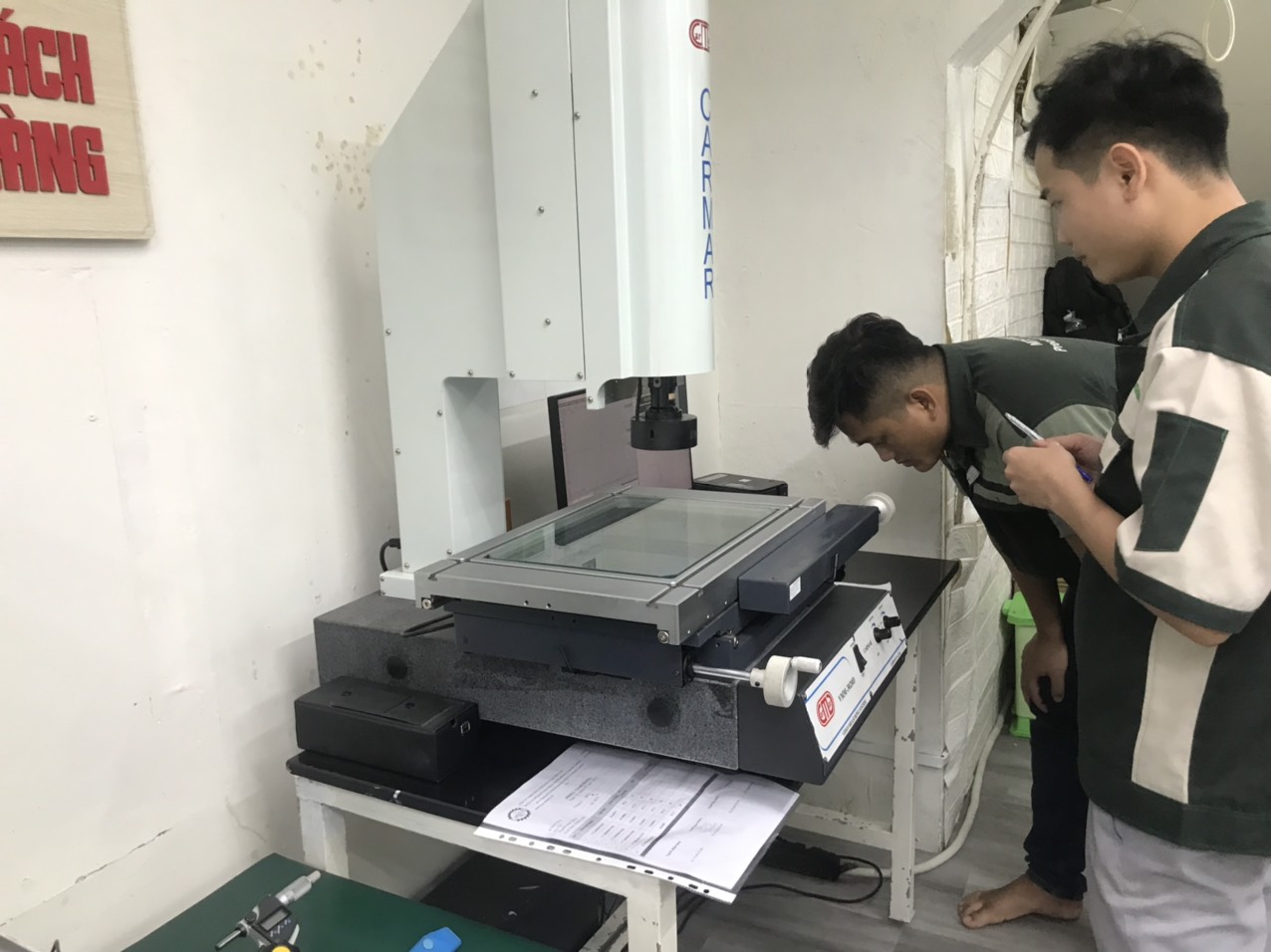
An optical comparator projects a magnified shadow of the part onto a screen. You overlay a template of the correct profile and visually compare. It is fast, non-contact, and effective for:
- Verifying bend radii
- Checking edge profiles on notched or stepped brackets
- Confirming hole positions in 2D
- Inspecting burr height along sheared edges
Our quality team uses profile projectors at 20× to 50× magnification. At these levels, a 0.05 mm deviation on a bend radius becomes clearly visible on the screen.
Vision Inspection Systems: Automated 2.5D Measurement
Vision measuring machines use high-resolution cameras and edge-detection software 7 to measure planar dimensions automatically. They offer several advantages over manual optical comparators:
- Programmable routines — measure the same features on every part identically
- Accuracy down to ±1–2 µm on modern systems
- No probe contact, so no risk of deforming thin stamped sheets
- Faster than CMM for flat or mostly-flat components
When we manage inspection for stamped mounting plates with multiple holes and slots, the vision system measures all hole positions, diameters, and slot widths in a single automated cycle. The software compares results to the CAD file and flags any out-of-tolerance feature.
3D Laser Scanners: Full-Surface Verification
For large or complex stamped parts — like automotive body brackets or multi-bend channel sections — a 3D laser scanner 8 captures millions of data points across the entire surface. The resulting point cloud is compared to the original CAD model to generate a color-coded deviation map.
This approach, sometimes called digital twin-to-part deviation mapping, shows exactly where the part deviates from nominal. It is especially valuable for detecting springback in formed features, which is a non-linear phenomenon that caliper spot-checks easily miss.
Emerging Technologies
The inspection landscape is changing. Some trends we are watching closely:
- In-line AI vision with edge computing — deep-learning algorithms that classify surface defects and geometric anomalies in real time during the stamping cycle
- Industrial computed tomography scanning — non-destructive measurement of internal features and hidden wall thicknesses in multi-component assemblies
- Free-fall optical inspection — parts drop through a measurement zone and every single component is checked at production speed, enabling 100% inspection instead of statistical sampling
- Acoustic emission and tonnage signature analysis — monitoring press force patterns to predict dimensional drift before it shows up in the parts
Choosing the Right Advanced Tool
| Part Characteristic | Recommended Tool | Why |
|---|---|---|
| Flat profile with holes and slots | Vision inspection system | Non-contact, fast, ±1–2 µm accuracy |
| Complex 3D form with GD&T | CMM with scanning probe | Full 3D geometric verification |
| Large panel or body bracket | 3D laser scanner | Captures entire surface for deviation mapping |
| 2D profile, bend radius, edge shape | Optical comparator | Quick visual comparison at magnification |
| Thin sheet (< 1.0 mm) | Vision system or laser scanner | Non-contact prevents part deformation |
| Internal bore, tight tolerance | Air gauging (pneumatic) | High resolution for tolerances ≤ 0.005 inch |
Air Gauging: A Niche But Powerful Option
Air gauging — also called pneumatic gauging 9 — deserves mention for stamped parts with precision bores. It measures internal diameters by monitoring changes in airflow through a calibrated nozzle. It is non-contact, extremely sensitive, and commonly specified for tolerances of 0.005 inch (≈0.127 mm) or tighter. We have used it on stamped bushings and cylindrical inserts where traditional pin gauges cannot provide the required resolution.
The Practical Workflow
In our day-to-day project management, the sequence for complex parts looks like this:
- Review drawing and identify critical vs. general dimensions.
- Use calipers and digital micrometers for general checks on the first samples.
- Run the part through an optical comparator or vision system for 2D profile verification.
- Send critical parts to CMM for full 3D GD&T analysis.
- If springback or surface deviation is suspected, scan with a 3D laser scanner.
- Document all results in the PPAP dimensional report.
- Design go/no-go fixtures for ongoing production floor use.
This layered approach catches defects at each stage and gives our US clients confidence that the parts will assemble correctly on arrival.
Conclusion
Verifying dimensional accuracy of stamping part samples requires a tiered strategy — manual tools for speed, optical systems for delicate profiles, CMMs for critical 3D features, and go/no-go gauges for production throughput. Match the tool to the tolerance, and you get it right the first time.
Frequently Asked Questions
What Are Go/No-Go Gauges?
A go/no-go gauge is a fixed-limit gauge. The "go" end represents the maximum material condition 6 — it must fit into or over the feature. The "no-go" end represents the minimum material condition — it must not fit. If the go end passes and the no-go end stops, the part is within tolerance.
How do I choose the right measurement tools for verifying my stamping part tolerances?
A purchasing manager once asked me why we use four different tools on one bracket. The answer is simple: each dimension on a stamped part has a different tolerance band, and no single instrument covers them all efficiently.
Can CMM inspection guarantee dimensional accuracy for my custom stamped components?
One lesson we learned early in our contract manufacturing work: a CMM report looks impressive, but it only guarantees what you program it to measure.
Footnotes
1. Standard system for defining and communicating engineering tolerances in manufacturing. ↩︎
2. Authoritative source for material properties, grades, and industrial applications of stainless steel. ↩︎
3. Measurement techniques that use light instead of physical probes to verify dimensions. ↩︎
4. Method for monitoring and controlling a process through statistical analysis of data. ↩︎
5. Authoritative Wikipedia entry providing a comprehensive overview of the PPAP quality standard. ↩︎
6. Geometric dimensioning term describing the state of a part at its limit of size. ↩︎
7. Detailed explanation of the algorithms and software principles used in automated vision inspection. ↩︎
8. Comprehensive resource explaining the technology and industrial applications of 3D scanning. ↩︎
9. High-precision measurement method using air pressure and flow for tight tolerances. ↩︎