

Inspecting stamping part samples the wrong way costs real money. Our team learned this early when a client’s brackets passed a basic size check, then jammed on his assembly line.
When inspecting stamping part samples, verify critical dimensions—hole diameter, hole position, bend angle, flatness, and material thickness—plus performance indicators like burr height, hardness, GD&T compliance, surface condition, and functional fit. Focus inspection on features that affect assembly, sealing, strength, and safety.
Not every dimension on a drawing deserves the same attention. In this article, I will show you which dimensions matter most, which indicators predict real-world performance, and how to inspect them properly.
How Do I Verify Critical Dimensions on Stamping Part Samples Before Approving Mass Production?
A few years back, our Vietnam office received a stamped Z-clip sample that measured perfectly on length and width. The slot was 0.08mm oversize. The whole batch would have failed.
Verify critical dimensions by identifying critical-to-quality features first—holes, slots, bend angles, and mounting surfaces—then measuring them against the drawing with calibrated tools. Prioritize dimensions that affect fit, fastening, and alignment rather than checking every dimension equally.

The mistake most buyers make is treating all dimensions as equal. They are not. A stamped bracket may have thirty dimensions on the drawing, but only five or six drive whether the part actually works. Our engineers call these critical-to-quality 1, or CTQ, dimensions. We mark them before the first sample ever arrives.
How to Identify CTQ Dimensions
Start with three sources. First, the drawing itself. Tight tolerances and GD&T callouts 2 signal importance. Second, customer notes. If your client mentions a mating part, every interface dimension becomes critical. Third, rejection history. If a similar part failed before, that dimension goes on the list.
For stamped brackets like the ones we source for U.S. clients, the priority order usually looks like this:
| Priority | Dimension Type | Why It Matters |
|---|---|---|
| 1 | Hole diameter and position | Drives fastening and assembly alignment |
| 2 | Slot width and location | Controls adjustability and clearance |
| 3 | Bend angle | Determines final shape and mating fit |
| 4 | Flange height | Affects stack-up in the assembly |
| 5 | Overall length and width | Ensures the part fits its housing |
| 6 | Material thickness | Confirms correct raw stock and strength |
Watch for Cumulative Error
Progressive dies 3 form parts across multiple stations. Errors compound station by station. A hole punched at station two can shift after a bend at station five. So we always measure hole position on the finished part, never on an intermediate strip. We also check both the round hole and the elongated slot on symmetrical brackets, because die wear rarely affects both features equally.
Before we approve mass production for any client, we require a full first-article inspection report with every CTQ dimension recorded, the tool used, and the actual measured value—not just a pass/fail checkbox.
What Performance Indicators Should I Check to Ensure Stamping Parts Meet Strength and Durability Requirements?
One trade-off we weigh constantly is speed versus depth of testing. A dimensional check takes minutes. A hardness or thinning check takes longer—but it catches failures that no caliper ever will.
Check burr height, material thickness retention, hardness at bend radii, surface defect rate, and functional fit. For load-bearing parts, add tensile or hardness testing. For drawn parts, verify percent thinning stays within limits, since excessive thinning weakens the part in service.
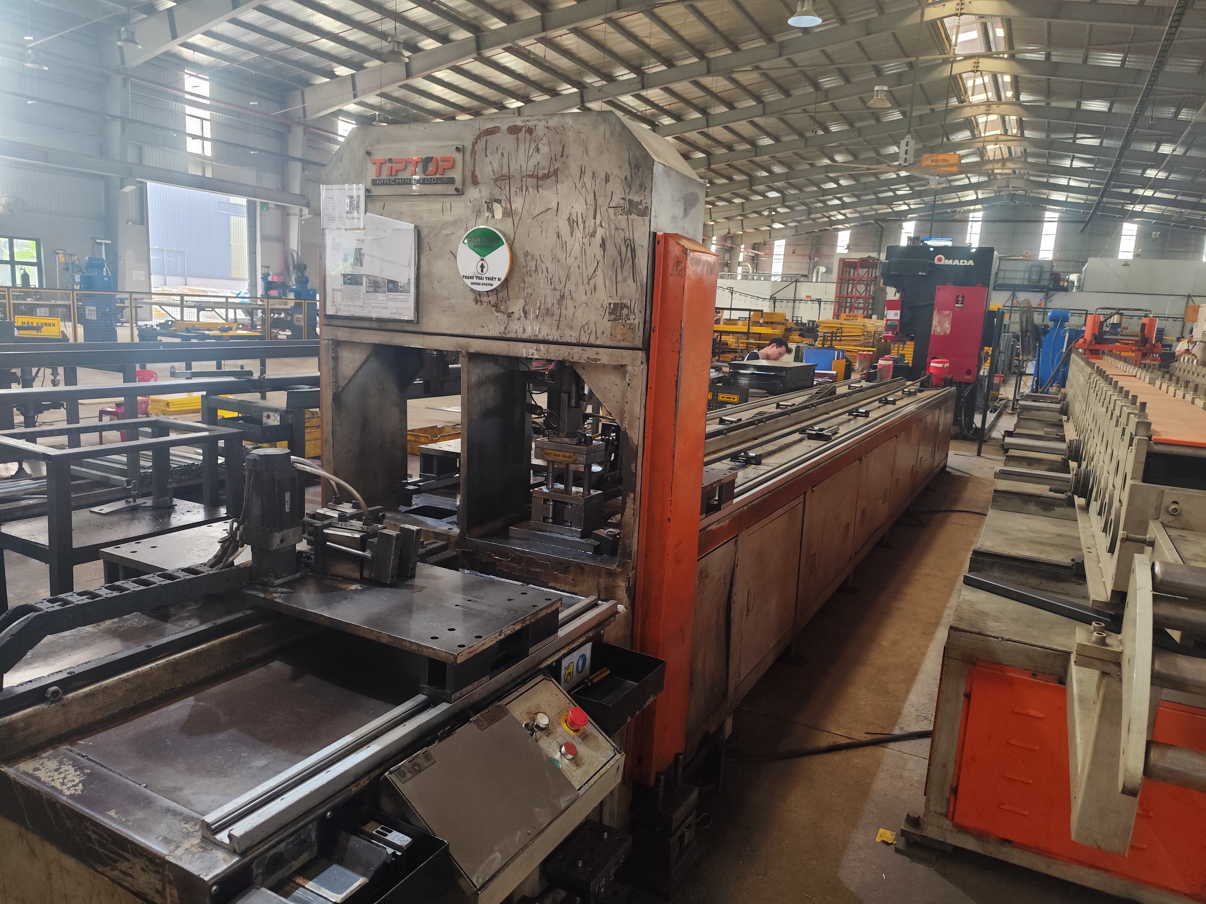
Dimensions tell you a part fits. Performance indicators tell you it survives. In our supplier audits across Vietnam and other Asian regions, we see many stamping shops that measure size well but ignore the indicators below. That gap is where field failures come from.
The Key Indicators and What They Reveal
| Indicator | What It Reveals | Typical Concern |
|---|---|---|
| Burr height | Cut quality and die sharpness | Often limited to a percentage of material thickness |
| Thickness retention | Material flow in drawn or stretched areas | Excessive thinning reduces load capacity |
| Hardness at bends | Cold-work effects during forming | Over-hardened zones can crack in service |
| Surface defect rate | Handling, die condition, lubrication | Scratches and dents hurt coatings and cosmetics |
| Functional fit | Real-world assembly behavior | Part must seat, clip, or fasten as intended |
| Coating thickness | Plating or galvanizing added after stamping | Adds measurable thickness that affects fit |
Why Hardness at Bend Radii Matters
Stamping is cold working. Every bend locally hardens the metal. On spring clips like the Z-fold fasteners we handle, that hardening is partly the point—it gives the clip its spring force. But too much hardening at a tight bend radius invites cracking, sometimes weeks after installation. So we ask suppliers to test hardness at the bend, not just on the flat blank.
Separate Base Metal from Coating
Zinc plating or galvanizing adds real thickness. On tight-fit parts, we measure base metal before plating and total thickness after. Mixing the two causes assembly interference that nobody can explain later. A functional fit check with the actual mating component is the final gate—if the part does not clip, seat, or fasten correctly, no dimensional report can save it.
Which Inspection Tools and Methods Help Me Accurately Measure Stamping Part Tolerances?
During a supplier audit near Ho Chi Minh City, I watched a QC technician check a ±0.05mm hole with worn calipers. The gauge was less accurate than the tolerance itself. That inspection was theater, not control.
Use calipers and micrometers for basic sizes, pin gauges for hole diameters, height gauges for flange heights, optical comparators for profiles and bend angles, and CMMs for true position and complex geometry. Match each tool's precision to the tolerance—measurement variation should stay under 10% of the tolerance band.

The rule is simple: the measuring tool must be much more precise than the tolerance it checks. When it is not, you get false accepts and false rejects, and you never know which is which.
Matching Tools to Features
| Feature | Recommended Tool | Notes |
|---|---|---|
| Length, width, flange height | Calipers, height gauge | Fast, good for tolerances above ±0.1mm |
| Material thickness | Micrometer | Measure away from burrs and coined edges |
| Hole diameter | Pin gauges | Go/no-go pins catch out-of-round holes calipers miss |
| Bend angle | Protractor, optical comparator | Comparators avoid contact distortion on thin parts |
| True position of holes | CMM | Essential for hole patterns and GD&T callouts |
| Flatness | Surface plate with feeler gauges, CMM | Check under free state unless drawing says otherwise |
| Burr height | Micrometer comparison, profilometer | Compare edge thickness to body thickness |
| Profile and contour | Optical comparator, vision system | Vision systems suit high-volume repeat checks |
Gage R&R: The Overlooked Step
A measurement system needs its own inspection. Gage repeatability and reproducibility studies tell you how much of your measured variation comes from the gauge and the operator rather than the part. Our rule of thumb, drawn from standard SPC practice, is that measurement variation should stay below 10% of the tolerance. If a hole tolerance is ±0.05mm, the gauge system needs to resolve differences far finer than that.
Thin stamped parts add one more trap: contact pressure. Calipers can flex a thin flange during measurement and produce a false reading. For thin-gauge clips, we prefer non-contact methods like optical comparators. We also verify calibration certificates for every tool used in a first-article report before we accept the data on behalf of our clients.
How Can I Ensure My Suppliers Follow Consistent QC Standards During Stamping Part Sample Inspection?
A purchasing manager in the U.S. once told me his biggest frustration: samples always passed, production always drifted. His suppliers inspected the sample once and never looked again. Tool wear did the rest.
Ensure consistency by requiring a documented first-article inspection, an agreed control plan listing CTQ dimensions and gauges, SPC monitoring with Cpk targets on critical features, calibrated equipment records, and periodic audits. Written acceptance criteria prevent supplier interpretation from drifting over time.
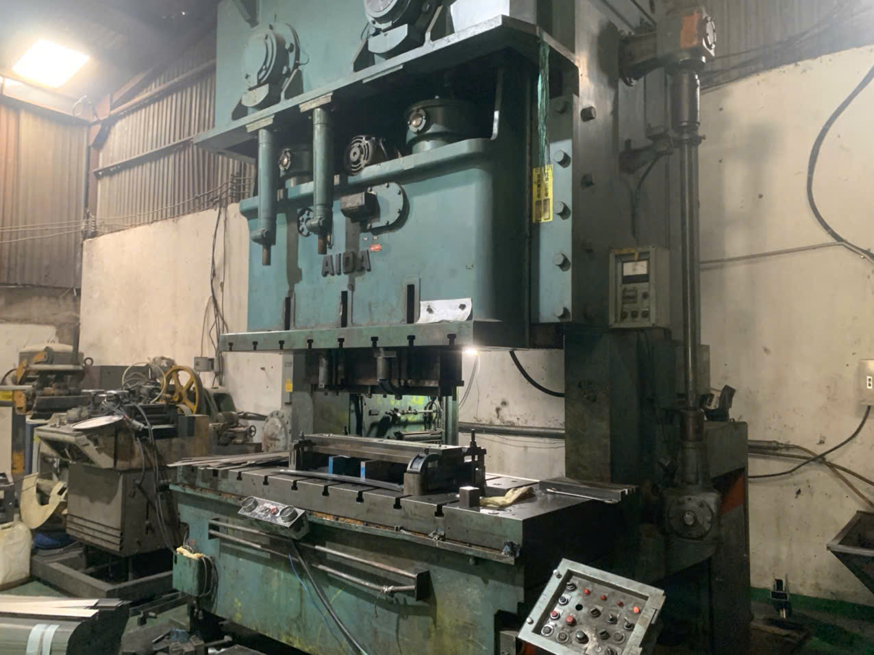
Sample approval is a snapshot. Production is a movie. The gap between the two is where most quality problems live, and closing it requires structure, not trust alone.
Build a Shared Control Plan
Before mass production starts, we sit down with the supplier and agree on a control plan 4. It lists every CTQ dimension, the gauge used, the sampling frequency, and the acceptance criteria. Nothing is left to interpretation. When we run PPAP 5 for our U.S. clients, this document becomes part of the approval package. The supplier signs it. We sign it. The client sees it.
Use SPC to Catch Drift Early
Bend angles drift as dies wear. Springback shifts as material lots change. One hundred percent inspection cannot fix this—it only sorts bad parts after they exist. Statistical process control 6 catches the drift before parts go out of tolerance. We ask suppliers to chart critical dimensions and react to standard SPC signals:
- Any point beyond the control limits.
- Repeated points close to a control limit.
- A run of points on one side of the centerline.
- A sustained trend upward or downward.
Where a drawing specifies a Cpk 7 target, we require capability data with each shipment, not just at sample stage. A dimension can be in tolerance today and incapable tomorrow.
Audit the Process, Not Just the Part
Our team in Vietnam visits stamping suppliers regularly. We check calibration records, look at the actual gauges on the shop floor, and watch operators measure. A supplier who measures a bend angle three different ways on three visits does not have a QC standard—he has habits. Written work instructions with photos fix that faster than any complaint email.
Conclusion
Focus stamping part sample inspection on CTQ dimensions, pair them with performance indicators, match gauges to tolerances, and lock suppliers into documented, SPC-backed QC standards. Inspect where failure is expensive.
Frequently Asked Questions
How Do I Verify Critical Dimensions on Stamping Part Samples Before Approving Mass Production?
A few years back, our Vietnam office received a stamped Z-clip sample that measured perfectly on length and width. The slot was 0.08mm oversize. The whole batch would have failed.
What Performance Indicators Should I Check to Ensure Stamping Parts Meet Strength and Durability Requirements?
One trade-off we weigh constantly is speed versus depth of testing. A dimensional check takes minutes. A hardness or thinning check takes longer—but it catches failures that no caliper ever will.
Which Inspection Tools and Methods Help Me Accurately Measure Stamping Part Tolerances?
During a supplier audit near Ho Chi Minh City, I watched a QC technician check a ±0.05mm hole with worn calipers. The gauge was less accurate than the tolerance itself. That inspection was theater, not control.
Footnotes
1. Background on CTQ methodology used to prioritize which stamped dimensions matter most. ↩︎
2. Explains the geometric dimensioning and tolerancing standard referenced for critical drawing callouts. ↩︎
3. Provides background on stamping and progressive die processes discussed in the article. ↩︎
4. ISO quality management standard relevant to documented control plans agreed with suppliers. ↩︎
5. Official source explaining the production part approval process referenced for supplier sign-off. ↩︎
6. Authoritative quality organization resource on SPC methods for catching process drift. ↩︎
7. NIST reference explaining process capability index calculations mentioned for capability data. ↩︎