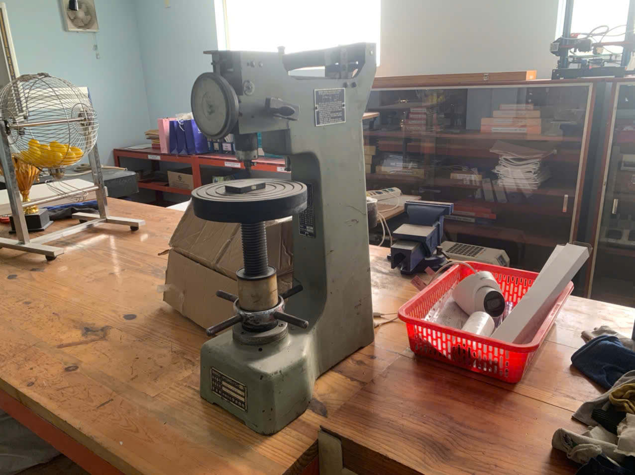
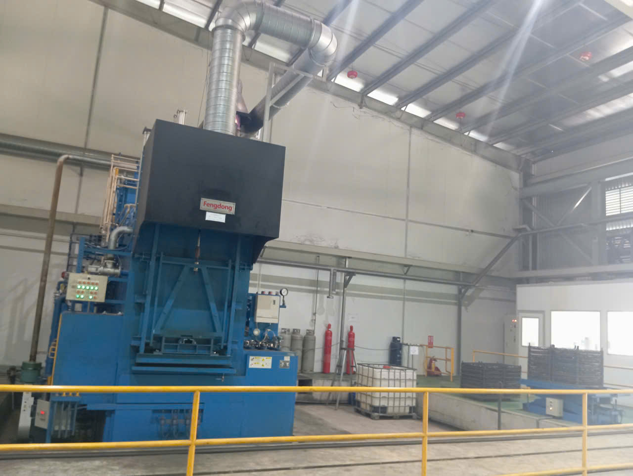
A recurring problem we see when managing stamping projects across Asia is buyers receiving parts that crack in assembly or wear out months early — all because heat treatment and hardness specs were vague or missing from the original drawing package.
Heat treatment and hardness for stamping parts determine whether a component can resist wear, maintain spring force, and hold dimensional stability over its service life. Choosing the right process — quenching and tempering, annealing, or case hardening — and specifying a precise hardness range prevents cracking, premature failure, and costly rework in production.
This guide breaks down the critical decisions you face when specifying heat treatment for stamped parts. We will cover process selection, hardness targets, supplier quality verification, and the defects that lead to expensive scrap. Each section draws on real scenarios our team encounters while coordinating precision metal stamping between U.S. buyers and Asian suppliers.
How Do I Choose the Right Heat Treatment Process for My Stamping Parts?
One trade-off our engineering team debates on nearly every new stamping project is this: do we stamp the part soft and harden it later, or do we source pre-tempered material 1 and skip the secondary process entirely? The answer is never one-size-fits-all.
Choose your heat treatment process based on part geometry, material grade, and final performance requirements. Simple shapes suit pre-tempered stamping; complex geometries with deep draws or tight bends need annealing first, then post-stamping hardening and tempering to prevent cracking while still achieving target hardness.
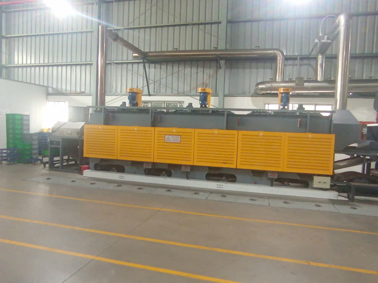
Pre-Tempered vs. Post-Stamping Heat Treatment
This is the first strategic decision. Pre-tempered stamping uses materials already in their final mechanical condition — blue temper steel, full-hard stainless steel, or pre-hardened spring steel. The part comes off the press ready to use. No secondary furnace step. No distortion risk from reheating. But you need higher press tonnage, and your tooling wears faster because you are forming harder material.
Post-stamping heat treatment works the opposite way. You stamp the part in an annealed or soft condition. The material flows easily into complex shapes. Then you send it through a hardening cycle — quenching and tempering 2 — to reach the required strength and wear resistance. This is essential when your geometry includes deep draws, sharp bends, or multi-stage forming that would fracture pre-hardened stock.
When Does Each Approach Make Sense?
| Factor | Pre-Tempered Stamping | Post-Stamping Heat Treatment |
|---|---|---|
| Part geometry | Simple bends, shallow forms | Complex shapes, deep draws |
| Tooling wear | Higher — forming harder material | Lower — forming soft material |
| Distortion risk | Minimal — no reheating | Present — must control cooling |
| Lead time | Shorter — no secondary process | Longer — added furnace step |
| Dimensional stability | Excellent as-stamped | Requires post-treatment inspection |
| Cost per piece (high volume) | Lower — fewer operations | Higher — added handling and furnace |
| Springback effect | Greater — harder material springs back more | Minimal during stamping — corrected after hardening |
In our experience exporting to the U.S., about 60% of stamping projects we manage use post-stamping heat treatment because the parts have features that simply cannot be formed from hard stock without cracking. The remaining 40% — mostly flat spring clips, simple brackets, and shims — use pre-tempered material to save time and reduce per-piece cost.
The Core Process Toolkit
Here is a quick reference for the most common heat treatment processes applied to stamping parts:
- Hardening (Quenching): Heat the part above its critical temperature (roughly 750 °C for high-strength steels 3), then cool it rapidly in oil, water, or gas. This creates martensite — a very hard but brittle microstructure. Tensile strength jumps dramatically.
- Tempering: Performed immediately after quenching. You reheat the part to a lower temperature to relieve internal stresses and convert brittle martensite into a tougher structure. This step is not optional. Skip it, and your parts will crack.
- Annealing process: Slow, controlled heating and cooling to restore ductility. Essential before multi-stage stamping or deep drawing. It recrystallizes the grain structure and eliminates work hardening from prior forming steps.
- Case hardening (Carburizing): Adds carbon to the surface layer, creating a hard shell (840–900 HV) over a softer, tougher core (410–550 HV). Carburizing depth for stamping components typically ranges from 0.02 to 0.12 mm.
- Stress relieving: A lower-temperature process that reduces residual stresses from stamping without significantly changing hardness. Useful for maintaining tight tolerances.
The right process depends on your material, your geometry, and what the part must do in service. When we review a new project, we always ask: what fails first — does the part crack, or does it wear out? That answer drives the process selection.
What Hardness Level Should I Specify to Avoid Cracking or Premature Wear?
A U.S. client once sent us a drawing that simply stated "harden after stamping" with no target range, no test location, and no scale. The supplier chose a hardness level that looked good on paper but made the part too brittle for its mounting application. It cracked during installation. That single omission cost three weeks and a full production re-run.
Specify hardness as a defined range on the Rockwell hardness scale (HRC), Vickers (HV), or Brinell (HB), matched to your part's function. Wear-critical surfaces typically need 470–510 HV or 48–52 HRC. Spring components need controlled ranges to maintain deflection force without cracking under cyclic load.

Understanding the Numbers
Hardness is not a single number. It is a range, and the scale you choose matters. Thin-gauge stamping parts — under 1 mm thick — often cannot be tested with standard Rockwell C indenters because the indenter would punch through the material. For these, Vickers micro-hardness (HV) is the correct method.
| Application | Typical Hardness Range | Recommended Scale | Notes |
|---|---|---|---|
| Hot-stamped structural parts | 470–510 HV | HV or HRC | Yield strength 950–1200 MPa |
| Carburized surface (case hardened) | 840–900 HV | HV | Core remains 410–550 HV |
| General brackets and mounts | 180–190 HB | HB | Moderate wear resistance |
| Spring clips and clamps | 42–50 HRC | HRC | Must hold spring force over life |
| Thin-gauge electronics stampings | 300–450 HV | HV (micro) | Too thin for standard Rockwell |
The Hardness vs. Ductility Trade-Off
This is the central tension. Every point of additional hardness reduces elongation — the material's ability to stretch before it breaks. For hot-stamped automotive parts, data shows that cooling rates above 60–80 °C per second produce a significant hardness increase, but elongation drops sharply. If your part must absorb energy or flex during use, pushing hardness too high makes it glass-like. It shatters instead of bending.
On our production oversight projects, we always ask the buyer: what is the failure mode you are designing against? If the part wears out, you need more hardness. If it cracks, you may already have too much. The answer dictates the target range.
Specifying Hardness Correctly on Your Drawing
A complete hardness callout includes four elements:
- Scale — HRC, HV, or HB
- Range — minimum and maximum (e.g., 44–48 HRC)
- Test location — surface, core, or a specific feature
- Sample size — how many pieces per lot must be tested
Never specify a single number. Always give a range. A callout of "45 HRC" gives the supplier no room for normal process variation. "44–48 HRC" tells them exactly where to aim and what is acceptable.
Work hardening from the stamping process itself also affects final hardness. Areas near bends and drawn features will test harder than flat sections, even before heat treatment. Your specification must account for this. If you specify hardness on a bent flange, expect it to read higher than the same material in a flat zone.
The Rockwell hardness scale 4 remains the most widely used for through-hardened stamping parts, but Vickers testing 5 is critical for case-hardened or thin-gauge components where surface hardness differs from core hardness. When we manage PPAP documentation 6 for our clients, we insist on hardness test reports that specify both the scale used and the exact measurement location on the part.
How Can I Verify My Supplier's Heat Treatment Quality Control Before Mass Production?
We learned this lesson during a project for a U.S. client sourcing mounting brackets from a Vietnamese supplier. The supplier's in-house heat treatment looked fine on the first samples. But when we audited the furnace logs during pre-production, we found temperature uniformity across the furnace varied by over 30 °C. That inconsistency meant parts from the center of a batch could be 4–6 HRC points softer than parts from the edges.
Verify your supplier's heat treatment quality by auditing furnace calibration records, reviewing temperature uniformity surveys, requiring hardness test reports with specific test locations, and demanding lot traceability. Request PPAP-level documentation including process capability studies before approving mass production.

The RFQ Checklist for Heat Treatment
Before you even receive a quote, your Request for Quotation should spell out every heat treatment requirement. Vague specs produce vague results. Here is what we include in every RFQ we issue on behalf of our clients:
Material specifications: Grade, thickness, starting temper condition, and whether a mill certificate is required.
Performance targets: Hardness range (with scale), spring force or deflection requirements, conductivity values if applicable, and any stress relief goals.
Process details: The specific heat treatment method (e.g., vacuum hardening, gas nitriding, salt bath quench), maximum allowable distortion, and the finish sequence — does heat treatment happen before or after plating?
Inspection requirements: Hardness test location on the part, sample size per lot, report format, and full lot traceability back to the raw material heat number.
Failure history: If you have had problems before — weak spring force, cracking, discoloration, or brittleness — document them in the RFQ. This gives the supplier context to avoid repeating mistakes.
What to Look For During a Supplier Audit
When our team visits a supplier's heat treatment facility, we check these items:
| Audit Item | What to Verify | Red Flag |
|---|---|---|
| Furnace calibration | Calibration certificates current, traceable to national standards | Expired certificates, no records |
| Temperature uniformity | Survey data showing ±5 °C or better across the furnace zone | No survey performed, or variance >15 °C |
| Quench media control | Oil temperature, agitation rate, contamination testing | No monitoring, dark or degraded quench oil |
| Hardness testing equipment | Calibrated tester with current certification | No calibration sticker, incorrect scale used |
| Process documentation | Written procedures for each heat treatment cycle | Operators relying on memory, no SOPs |
| Lot traceability | Parts traceable to furnace batch, time, temperature, and raw material lot | Mixed lots, no batch identification |
Beyond the Audit: Ongoing Verification
A one-time audit is not enough. We require our suppliers to submit hardness test data with every shipment. We also perform incoming inspection at our own facility — spot-checking hardness on a statistical sample. For critical parts, we request cross-sectional micro-hardness profiles to verify case depth on carburized components.
Vacuum heat treatment is increasingly common for precision electronics stampings. It prevents oxidation and eliminates the need for post-treatment pickling or chemical cleaning 7, which is both an environmental and quality advantage. When evaluating suppliers, we give preference to those with vacuum furnace capability for parts that require a bright, clean surface finish.
Predictive simulation software — CAE tools that model phase transformations and thermal distortion — is another indicator of a capable supplier. The best suppliers can predict dimensional changes before the first part enters the furnace, allowing them to compensate in the die design. This directly supports the "right first time" outcome that our U.S. clients demand.
What Heat Treatment Defects Should I Watch For to Prevent Costly Rework?
During a recent production run of Z-shaped spring clamps — similar to the stamped clips we frequently manage — our quality team caught a batch where the parts looked perfect visually but failed the hardness test by 8 HV points on the gripping lip. The root cause was decarburization: a thin layer of carbon had burned off the surface during an improperly controlled furnace atmosphere. The surface was softer than the core. Those parts would have worn out in months instead of years.
Watch for decarburization, uneven hardness, quench cracking, excessive distortion, and retained austenite. These heat treatment defects compromise tensile strength, dimensional stability, and fatigue life. Detecting them requires hardness testing at multiple locations, visual inspection under magnification, and microstructure verification on sample parts.
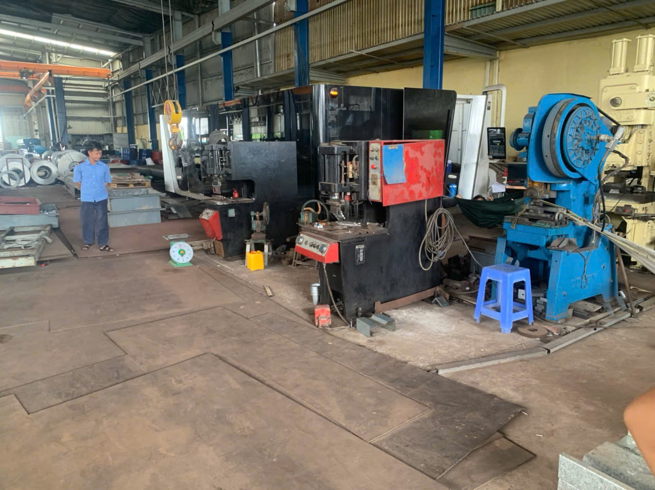
The Most Common Heat Treatment Defects
Not all defects are visible. Some of the most dangerous ones hide beneath the surface. Here is what we train our inspectors to look for:
Decarburization occurs when carbon is lost from the surface layer during heating in an uncontrolled atmosphere. The surface becomes softer than specified. It reduces wear resistance and fatigue life. Vacuum heat treatment eliminates this risk entirely.
Quench cracking happens when cooling is too rapid or uneven. Sharp corners, holes, and thickness transitions are high-risk areas. The thermal shock creates internal stresses that exceed the material's strength. Parts crack — sometimes immediately, sometimes days later. This is why tempering must follow quenching without delay.
Excessive distortion is a dimensional problem. Heat treatment changes the part's shape. Flatness, coplanarity, and hole-to-hole distances can all shift. For precision stamping parts, specifications must include post-treatment dimensional tolerances. Our team always measures critical dimensions after heat treatment, not just after stamping.
Retained austenite is a microstructural issue. If quenching does not fully convert austenite to martensite, the soft austenite 8 remains in the structure. The part tests softer than expected and may dimensionally change over time as the retained austenite 9 slowly transforms. Deep cryogenic treatment at approximately -185 °C can convert retained austenite into stable martensite, increasing wear resistance by a significant margin.
Uneven hardness across a batch — or even across a single part — points to furnace problems. Poor temperature uniformity, inconsistent quench agitation, or overloaded furnace baskets are common causes.
How to Catch Defects Before They Ship
A robust inspection plan is your last line of defense. Here is what we recommend based on years of managing these projects:
- Hardness testing at multiple locations — test the body, the bend, and any wear surface. Compare readings to confirm uniformity.
- Visual inspection under 10× magnification — look for micro-cracks near holes and bends, surface discoloration indicating decarburization, and scale buildup.
- Dimensional inspection post-heat-treatment — measure flatness, coplanarity, and critical features. Compare to pre-treatment readings to quantify distortion.
- Microstructure verification — on the first article and periodically during production, section a sample part and examine the grain structure under a metallurgical microscope. This confirms proper transformation and adequate case depth for carburized parts.
- Magnetic particle or dye penetrant inspection — for high-stress parts, these non-destructive methods reveal surface and near-surface common quality defects invisible to the naked eye.
Tailored property stamping — where a single part has localized hardened zones for wear resistance alongside ductile sections for assembly or energy absorption — adds another layer of complexity. Each zone must be tested independently. The tool steel grades 10 used in the stamping dies themselves also require proper heat treatment to maintain die life and part consistency across long production runs.
The cost of catching a defect at incoming inspection is a fraction of the cost of a field failure. When we set up process control plans for our clients, we build these checks into every production lot. It is the only way to ensure that what ships matches what was specified.
Conclusion
Heat treatment and hardness for stamping parts are not afterthoughts — they are core engineering decisions that determine whether your parts perform or fail. Specify clearly, audit thoroughly, inspect consistently, and partner with a supply chain team that understands every step from die to delivery. For a deeper dive into how heat treatment changes mechanical properties when sourcing sheet metal, and to learn how to choose the right material for metal stamping parts, explore our related guides.
Frequently Asked Questions
How Do I Choose the Right Heat Treatment Process for My Stamping Parts?
One trade-off our engineering team debates on nearly every new stamping project is this: do we stamp the part soft and harden it later, or do we source pre-tempered material 1 and skip the secondary process entirely? The answer is never one-size-fits-all.
What Hardness Level Should I Specify to Avoid Cracking or Premature Wear?
A U.S. client once sent us a drawing that simply stated "harden after stamping" with no target range, no test location, and no scale. The supplier chose a hardness level that looked good on paper but made the part too brittle for its mounting application. It cracked during installation. That single omission cost three weeks and a full production re-run.
How Can I Verify My Supplier's Heat Treatment Quality Control Before Mass Production?
We learned this lesson during a project for a U.S. client sourcing mounting brackets from a Vietnamese supplier. The supplier's in-house heat treatment looked fine on the first samples. But when we audited the furnace logs during pre-production, we found temperature uniformity across the furnace varied by over 30 °C. That inconsistency meant parts from the center of a batch could be 4–6 HRC points softer than parts from the edges.
Footnotes
1. Explains the tempering process used to achieve specific mechanical properties in steel before or after forming. ↩︎
2. Authoritative reference for quenching and tempering heat treatment processes. ↩︎
3. Authoritative source on the properties and industrial applications of advanced high-strength steels in manufacturing. ↩︎
4. Comprehensive reference for the Rockwell scale and its various applications. ↩︎
5. Detailed technical explanation of the Vickers hardness testing methodology. ↩︎
6. Defines the industry-standard process for ensuring supplier quality and production consistency for manufactured parts. ↩︎
7. Overview of industrial cleaning agents used to remove surface contaminants and oxidation after heat treatment. ↩︎
8. Scientific explanation of the austenite phase and its mechanical properties. ↩︎
9. NASA research on how cryogenic treatment stabilizes metal microstructures by converting retained austenite into martensite. ↩︎
10. Detailed classification and standard grades of tool steels used in manufacturing. ↩︎